Air Slide Table MXJ Series
Maximum Allowable Load Mass: m max
Maximum Allowable Moment (Reference Values)
Allowable Kinetic Energy: J
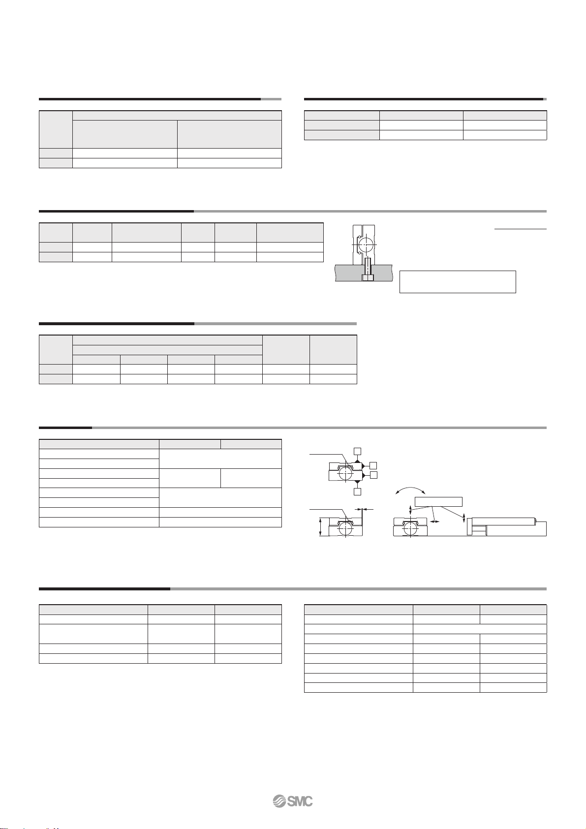
Accuracy
Adjuster Specifications/Refer to page 11 for adjuster models and dimensions.
Stroke 10, 20, 30 50
B side parallelism to A side 0.03 mm
E side parallelism to D side
B side traveling parallelism to A side
0.005 mm 0.008 mm
E side traveling parallelism to D side
M dimension tolerance ±0.05 mm
W dimension tolerance
End deflection ±0.003 mm
Non-rotating table accuracy (deg) at the retracted end
±0.02
∗ The table displays the values for an unloaded, unpressurised cylinder
without deflection. The values are recorded at 20°C ±5°C.
Weight of Moving Parts: m1
Model
Weight of moving parts Additional
weight of
magnet
Additional weight
of adjustment
block
Stroke [mm]
10 20 30 50
MXJ12 96 99 115 147 0.61 16
MXJ16 138 147 168 211 0.61 30
Model
Maximum load mass
Without adjuster
Rubber stopper
Shock absorber
Metal stopper with bumper
Metal stopper
MXJ12 0.8 0.5
MXJ16 1.5 1
Model Pitch, Yaw Roll
MXJ12 4.5 5.3
MXJ16 6.4 9.2
∗ A model cannot be selected with the maximum allowable moment.
Select a model according to the model selection steps on page 19.
Model Without
adjuster
Metal stopper
with bumper
Rubber
stopper
Shock
absorber Metal stopper
MXJ12 0.05 0.015 0.05 0.245 0.012
MXJ16 0.069 0.023 (0.017)∗10.069 0.49 0.02 (0.014)∗1
Kinetic energy E [J] =
m1: Weight of cylinder moving parts
kg
m2: Load mass kg
V: Piston speed at the end m/s
(m1 + m2)V2
2
V = 1.4 Va
Va: Average piston speed
Side mounting
E
D
B
A
Non-rotating accuracy
End deflection
M
W
Groove for
reference
Groove for
reference
[kg] [N·m]
[J]
[g]
Shock Absorber/RJ
Model MXJ12 MXJ16
Stroke absorption [mm] 4 6
Collision speed [mm/s] 50 to 500
Max. operating frequency [cycle/min]
20 42
Max. allowable thrust [N] 150 245
Spring force (Extended) [N] 1.3 2.8
Spring force (Compressed) [N] 3.9 5.4
Mounting screw size M6 x 0.75 M8 x 1
Shock absorber part number RJ0604N RJ0806LN
Metal Stopper with Bumper
Model MXJ12 MXJ16
Stroke absorption [mm] 2 2.8
Min. operating pressure of metal
stopper with bumper∗
1
[MPa]
0.3 0.3
Full compression force of bumper [N]
20 42
Mounting screw size M6 x 0.75 M8 x 1
∗1 Minimum operating pressure required to fully compress the protrusion
of the bumper to get in contact with the metal part
When using the metal stopper with bumper for positioning, use it at a
pressure level exceeding the minimum operating pressure. For vertical
mounting, the workpiece mass should be taken into consideration. For
details, refer to Specific Product Precautions on page 24.
∗1 When the MXJ16 is side mounted and used with metal stoppers or metal stoppers
with bumper, keep the kinetic energy below the value shown in brackets ( ).
∗Average piston speed: Speed that the stroke
is divided by a period
of time from starting
the operation to reach-
ing the end.
6