manuals.online logo
Brands
  1. Home
  2. •
  3. Brands
  4. •
  5. SMC Networks
  6. •
  7. Measuring Instrument
  8. •
  9. SMC Networks PPA Series User manual

SMC Networks PPA Series User manual

F.R.L.
AV
AU
AF
AR
IR
VEX
AMR
ITV
IC
VBA
VE
VY1
G
PPA
AL
Peak display Bottom display
MPa
POWER
LIGHT
MPa
POWER
LIGHT
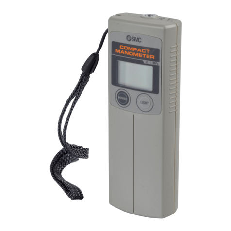
Pressure measurements can easily be taken any time, anywhere.
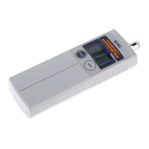
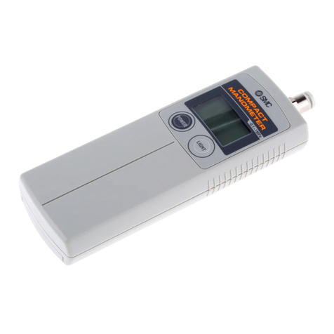
Compact Manometer
Series PPA
 Compact and lightweight
Portable type with a lightweight of only about 100 g
(unit 50 g, battery 50 g) can also be held in the palm of the hand.
 Long service life of 12 months continuous operation
One year of continuous operation is possible with 2 type AA batteries (3 V).
 Convenient hand strap for carrying
Keeping practical use in mind, the hand strap is a standard feature.
 Zero/span calibration is possible
Offset adjustment with the zero clear function, and span calibration with the trimmer
can be performed.
 Peak/Bottom hold function
With pressure being displayed, variations in supply pressure can be grasped instantly
with one touch switching of the display from peak value to bottom value.
 Auto power off function to save batteries
Power turns off automatically if not operated for more than 5 minutes.
 Case holder is available
The case holder is provided as an option to allow for situations where portability is not
required.
 Back light for easy viewing in dark locations
14-12-1
1
Application Example
Confirmation of air line
source pressure
Human reading error is eliminated by
the ability to confirm line pressure on
the digital display.
It is also possible to check pulsation in
the source pressure using the peak/bot-
tom display funcion.
Setting a regulator can be performed
more precisely than with a dial
gauge by viewing the digital display
while making the setting.
Furthermore, power lines are not
needed for this battery operated unit.
Related products for line pressure measurement
Can also be used as an energy saving related device
Tube coupler
Finger valve
For specifications, refer to page 14-12-4.
IN-442-5
Pressure probe
Confirmation of regulator
set pressure
Compact Manometer
Series PPA
Convenient for easy line pressure measurement without re-
moving piping or stopping supply pressure, etc.
Pressure can be sup-
plied or stopped by in-
serting or removing
the tube.
Pressure can be easi-
ly applied or released
by switching the con-
trol. Used in combination with the pressure probe (IN-
442-5), total pressure can be easily measured.
Pressure measurements
can easily be
taken any time, anywhere.
Measures the total pressure received by
an air blown workpiece
Series PPA
14-12-2
2
F.R.L.
AV
AU
AF
AR
IR
VEX
AMR
ITV
IC
VBA
VE
VY1
G
PPA
AL
1. The compact manometer can be used for
measurement of air and non-corrosive gases.
Please note that the accuracy of measurement for other fluids
cannot be guaranteed. Furthermore, the construction is not
explosion proof, and therefore, flammable gases should not
be used.
2. Be certain to stay within the rated pressure range.
Operation outside the pressure range will cause failure.
3. Do not intentionally swing around by the hand
strap.
If the strap breaks or comes loose, there is a danger of injury
or damage, etc.
4. When installing or removing One-touch fittings on
tubing, first confirm that the fluid to be measured is
at atmospheric pressure.
If tubing is disconnected while the fluid to be measured is in a
pressurized state, the tubing may jump causing a danger of
injury or damage. Also when connecting tubing, confirm that it
is securely attached.
5. Instruction manual
Read it carefully and understand the contents before using a
product. Also, keep the manual in a location where it can be
referred to at any time.
Handling
Warning
1. Keep condensate and foreign matter from getting
into the fluid to be measured.
If condensate or foreign matter is mixed in the fluid to be
measured, this may cause failure or air leakage.
If there is a possibility of these being contained in the fluid,
use the meter via a filter or mist separator.
2. Do not drop or strike the unit, etc.
Do not drop, strike or apply a large impact shock (980 m/s2),
as this may result in a failure.
3. Be certain to perform the zero clear function with
pressure released to the atmosphere.
When perfoming the zero clear function, this should be done
with piping ports in an atmospheric release condition. If
adjustment is performed at a pressure other than atmospheric
pressure, the correct value will not be displayed.
4. Tighten One-touch fittings in accordance with the
following.
One-touch fittings should first be tightened by hand, and then
further tightened approximately 1/6 of a turn using a tightening
tool. If screwed in too far, this may cause air leakage due to
breaking of threads or distortion of the gasket, etc. If not
screwed in far enough, this may cause a loose fitting or air
leakage, etc.
Caution
1. Absolutely never use in an atmosphere where
explosive gases are used.
The compact manometer does not have explosion proof
construction. If used in an atmosphere of explosive gases,
there is a possibility of causing an explosion, and therefore,
should absolutely not be used under these conditions.
Operating Environment
Warning
1. Do not use where there is splashing of water or oil,
etc.
The compact manometer is not a dusttight and dripproof type,
and should not be used where there is splashing water or oil,
etc., as this may result in a malfunction.
Caution
1. Perform maintenance and inspection on a regular
basis.
If there is an unintended misaction, misoperation, etc., or
calibration has not been performed, there is a possibility of an
incorrect value being displayed, making it impossible to
ensure safety.
2. Do not disassemble or modify the unit.
Maintenance and Other
Warning
1. Use manganese type AA dry batteries (R6) or
alkaline type AA dry batteries (LR6).
Do not use batteries other than the above, as this may cause
failiure.
2. Insert the plus (+) and minus (–) terminals of the
batteries in the proper direction as indicated inside
the unit.
If the batteties are inserted incorrectly, this may cause them to
leak or explode and result in damage to the unit.
3. Do not use old and new batteries or mix different
types of batteries together.
This may cause batteries to leak and result in damage to the
unit.
4. Remove the batteries when the unit will not be
used for a long period.
5. Do not use batteries if their voltage has dropped.
Continuing to use them may lead to the display of incorrect
values.
6. Do not touch the span calibration trimmer except
when performing span calibration.
Touching the trimmer may cause generation of an error in the
measured pressure. Also do not turn it too hard (0.3 N·m or
less) or press it too hard (5 N or less).
7. Use a soft cloth to wipe the blot off of the body.
In case of heavy soiling, wipe it off with a cloth soaked in a
neutral detergent diluted with water after wringing it out
thoroughly, and finish up by wiping with a dry cloth.
Caution
Precautions
Be sure to read before handling. Refer to pages 14-21-3 to 14-21-4 for Safety Instructions and Common
Precautions.
14-12-3
3
How to Order
None
With PPA-B
Nil
B
With the unit switching function(1)
Fixed in SI unit (2)
Nil
M
Option/Case holder
Unit specifications
PPA10
One-touch fitting type
ø4 (mm size)
ø6 (mm size)
Nil
04
06
0M
–0.1 to 1 MPa (For high pressure)
–101 to 10 kPa (For vacuum)
–10 to 100 kPa (For low pressure)
0
1
2
Applicable tubing size
Symbol
KJH04-M5
KJH06-M5
One-touch fitting
None
Applicable tubing material
Nylon
Soft nylon
Polyurethane
NoneNone
Model
Rated pressure range
Pressure display
Pressure display discrimination
Mini. display units
Error display
Function
Withstanding pressure
Fluid
Power supply
Battery life
Response speed
Display accuracy
Repeatability
Temperature characteristics
Piping port
Ambient operating temperature
Ambient operating humidity
Shock resistance
Enclosure
Weight
Specifications
–101 to 10 kPa
3 digit LCD back light
1/100
Over pressure, Memory data error, Change battery sign
200 kPa
Air, Non-corrosive gases
3 V (DC), Type AA dry cell x 2 pcs.
12 months continuous operation (Without backlighting, temperature conditions: at 25°C)
250 ms
±2% F.S. or less (Temperatue conditions: at 25°C)
±1% F.S. or less (Temperatue conditions: at 25°C)
±3% F.S. or less (0 to 50°C with 25°C standard)
M5 x 0.8
0 to 50°C (With no condensation)
35 to 85% RH (With no condensation)
980 m/s2X, Y, Z directions, 3 times each
IP40 (IEC standard)
Approx. 100 g (Unit 50 g, batteries 50 g)
–0.1 to 1 MPa
PPA100 for high press.
–10 to 100 kPa
Peak/bottom display, Backlight, Auto power OFF
Zero clear, Units display switching
PPA101 for vacuum
PPA102 for low press.
1.5 MPa 200 kPa
kPa
MPa
mmHg
kgf/cm2
inHg
PSI
bar
——
0.01
——
0.1
——
1
0.1
1
——
5
0.01
0.2
0.1
0.01
1
——
——
0.01
——
0.1
0.01
Note)
Series PPA
PPA100/101/102
Pressure specifications
Note 1) With unit switching function is not
permitted to sell for the domestic
use in Japan, because the new
Weight and Measure Act has
been implemented since October
’99.
Note 2) Fixed unit
For vacuum/compound pressure:
kPa For positive pressure: MPa
∗ 2 pcs. of type AA dry batteries (manganese R6 or alkaline LR6) are not included.
Note) For the unit switching function (Types without the unit switching function is fixed in SI unit (kPa or MPa).)
Compact Manometer
14-12-4
4
(PPA100 shown, Unit: MPa)
Description of Operating Parts Operation and Functions
Power ON
Power OFF
•When pressed and held
for 3 seconds or more,
the power turns OFF.
•When there is no button
operation for more than
5 minutes, the power
turns OFF. (auto power
OFF function)
Initial Setting
1. When the power is
applied, and “Err” is
displayed on LED,
cut the power off for
a time. After turning
OFF (i.e. the state in
which nothing is
displayed on LCD),
then proceed to 2.
Besides, in the case
that nothing is
displayed on LCD,
proceed to 2 with
doing nothing.
2. Press and hold for 6
seconds or more.
The unit will go into
zero clear. When this
happens “CAL” will
appear on the LCD.
3. When zero clear is
finished, the unit can
be operated.
3. Release the
POWER button.
2. Press and hold the
POWER button for 6
seconds or more.
1. Confirmation of
display
“P” for peak display
“b” for bottom display
In lock mode
Power button
• Power ON/OFF
• Peak mode switching
LCD
• Present pressure display
• Peak/bottom value display
• Units display
LIGHT button
• Turns on back light
MPa
POWER LIGHT
MPa
POWER LIGHT
POWER LIGHT
MPa
POWER LIGHT
MPa
POWER LIGHT
MPa
POWER LIGHT
•The power comes ON
as it is pressed.
•When pressed and held
for 6 seconds or more,
the unit goes into zero
clear.
Press the POWER
button.
Press and hold the
POWER button for 3
seconds or more.
Be certain to perform initial setting when
using for the first time and after changing
batteries, as the unit will indicate memory
data error.
14-12-5
Compact Manometer Series PPA
F.R.L.
AV
AU
AF
AR
IR
VEX
AMR
ITV
IC
VBA
VE
VY1
G
PPA
AL
5
Turning on the Backlight
It normally lights up
while the button is be-
ing pressed. In the lock
mode, it lights up when
pressed and turns off
when pressed again.
However, the maxi-
mum lighting time is
approximately one min-
ute.
Zero Clear
The zero point dis-
played at atmospheric
pressure can be auto-
matically adjusted. By
this means it is possi-
ble to eliminate a dis-
play discrepancy at at-
mospheric pressure.
• Turn the power OFF.
•Release the supply
pressure to the at-
mosphere.
•When continuously
pressed for 6 sec-
onds or more, zero
clear is performed
and “CAL” is dis-
played on the LCD.
Lock Mode (Auto power OFF cancel)
The auto power OFF
function is canceled by
activating the lock
mode (auto power OFF
cancel).
When continuously
pressed for 6 seconds
or more, “L” is dis-
played on the LCD.
Moreover, when the
power is turned OFF,
the lock mode is re-
leased.
Auto Power OFF Function
When the power is
turned ON and there is
no button operation for
more tham 5 minutes,
the power will turn
OFF.
Note) For cancelling
this function, refer to
the functions and oper-
ation of the lock mode
(below).
MPa
POWER
LIGHT
MPa
POWER
LIGHT
MPa
POWER
LIGHT
Peak/Bottom Display
Do this when pressure
is being displayed.
Peak display
Displays the maximum
pressure value and “P”
appears on the LCD.
The display will change
if pressure increases
beyond the pressure
value that is being held.
Bottom display
Displays the minimum
pressure value and “b”
appears on the LCD.
The display will change
if pressure falls below
the pressure value that
is being held.
(These modes are
convenient for con-
firming pressure fluc-
tuations.)
Press the POWER button.
MPa
POWER
LIGHT
MPa
POWER
LIGHT
MPa
POWER
LIGHT
Press the POWER button.
POWER
LIGHT
Press the LIGHT button.
Press the POWER button
for 6 seconds or more.
Unit Display Switching
1.When pressed con-
tinuously for 3 sec-
onds or more, the
unit on the LCD will
flash.
2.
The unit will change.
(See the table below.)
3. The unit is set, and
switching is finished.
MPa
MPa
bar
Note) The “inHg” unit cannot be displayed.
High pressure
(PPA100)
MPa  bar
 PSI  kgf
Vacuum
(PPA101)
kPabar  PSI
 inHg  mmHg
Low pressure
(PPA102)
kPa  bar
 PSI  kgf
kgf
POWER
LIGHT
kgf
POWER
LIGHT
MPa
POWER
LIGHT
2. Press the LIGHT
button.
3. Press the POWER
button.
(PPA100 shown, Unit: MPa)
Operation and Functions
Note) This operation cannot be done for
the type which does not have the
unit switching function.
Note) Since this is combined with power
OFF operation, the button should
be released at the point when “P”
or “b” is displayed.
1. Press and hold the
POWER and LIGHT
buttons for 3 sec-
onds or more.
Press and hold the
POWER and LIGHT but-
tons for 6 seconds or
more.
14-12-6
Series PPA
6
Dimensions
ø4
ø6
ø1/4"
123
124
126
Note) Dimension X includes
the One-touch fittng
(Back)
20
5Fitting port diameter
M5 x 0.8
Thread depth 5
40
20
LIGHT
POWER
180
X Refer to Note)
110
(Front)
BATTERY 1.5 Vx2 LR6, R6P
MADE IN JAPAN AX
LIGHT
POWER
LOCK MODE(AUTO POWER OFF CANCEL)
PPA100
Connecting tube port
Accessory One-touch fitting
Body
Span calibration
Type AA dry batteries (2 pcs.)
+
–
–
+
Option/Case holder
SMC
44
9.2
4.5
152518
120
ø4.5
2-(R)
2
6.8
29
14-12-7
Compact Manometer Series PPA
F.R.L.
AV
AU
AF
AR
IR
VEX
AMR
ITV
IC
VBA
VE
VY1
G
PPA
AL
7
Error Correction Maintenance
When errors occur, they should be corrected as shown below.
Display Contents Corrective action
Pressure being applied is
above the rating.
Memory data has probably
been corrupted in some way.
Operate within the rated
pressure range.
Perform auto zero adjustment.
Battery voltage is low. Replace the batteries.
Entire display flashes
Caution
Caution
Trimmer
Standard
pressure gauge
Compact
manometer
Compressor
Related Products Useful for Measuring Line Pressure
Valve type
Fluid
Proof pressure
Maximum operating pressure
Operating vacuum pressure∗
Ambient and fluid temperature
Applicable tubing material Note)
Option
2 port valve, 3 port valve
Air
1.5 MPa
1.0 MPa
–100 kPa
0 to 60°C
Nylon, Soft nylon, Polyurethane
Bracket
Finger valve
Series VHK
Specifications
Note) Use caution with soft nylon and polyurethane at the maximum operating
pressure. (For details, refer to Best Pneumatics Vol. 15.)
∗For a vacuum application, use VHK2 (2 way valve).
JIS Symbol
Tubing material
Tubing O.D.
Self-seal fittings
Series KC
Applicable Tubing
Fluid
Maximum operating pressure
Proof pressure
Ambient and fluid temperature
Thread
Seal (Thread portion)
Adaptor for copper family
incompatible parts
Air
1.0 MPa
3.0 MPa
0 to 60°C
JIS B 0203 (Taper threads for piping)
JIS B 0211 Class 2 (Metric fine thread)
With seal (Standard)
Part C3604BD (Electroless nickel plated)
Specifications
Nylon, Soft nylon, Polyurethane
ø4, ø6, ø8, ø10, ø12
Mounting section
Nut section
Body
Stud
Chuck spring
Guide
Collet release bushing
Valve retainer
Stopper
Seal O-ring
C3604BD, PBT
C3604BD (Thread portion)
Stainless steel 304
C3604BD, Polyacetal (POM)
POM
POM
C3604BD, Polyacetal (POM)
NBR
Principal Parts Material
These products are convenient for measuring line pressure easily without the need to remove piping or stop supply pressure, etc.
2 port valve 3 port valve
A
II
PRP
A
For details, refer to Best Pneumatics Vol. 15.
앬Span calibration method
Do not touch the span calibration trimmer except when
performing span calibration.
1. Perform zero clear at atmospheric pressure.
2. Apply the maximum rated pressure, and calibrate the span while
comparing with a standard pressure gauge.
3. If the display value of the compact manometer is “0” after returning
to atmospheric pressure, then calibration is complete.
If the display value is not “0”, calibrate again by repeating steps 1
and 2.
앬Replacing the batteries
When battery voltage becomes low the entire LCD will flash.
When the LCD flashes replace the batteries. Use 2 pcs. of type AA
dry batteries.
To replace the batteries, turn the power OFF and replace them
within approximately 30 seconds.
When not completed within 30 seconds, “Err” will be
displayed. In that case, perform zero clear once again.
In the event that the display runs out of control, remove the
batteries for one minute or longer, and then perform zero clear
again for inserting the batteries and turning on the power.
Switching between pressurization and atmospheric re-
lease can be easily performed by switching the control.
Pressure can be supplied or stopped by inserting or re-
moving a tube.
14-12-8
Series PPA
8

Other manuals for PPA Series

1

This manual suits for next models

4

Other SMC Networks Measuring Instrument manuals

SMC Networks IZH10 Series User manual

SMC Networks

SMC Networks IZH10 Series User manual

SMC Networks Prime-600 User manual

SMC Networks

SMC Networks Prime-600 User manual

SMC Networks PFMV3 Series User manual

SMC Networks

SMC Networks PFMV3 Series User manual

SMC Networks IZH10 Series Manual

SMC Networks

SMC Networks IZH10 Series Manual

SMC Networks ZSE30AF series User manual

SMC Networks

SMC Networks ZSE30AF series User manual

SMC Networks PFM3 Series User manual

SMC Networks

SMC Networks PFM3 Series User manual

SMC Networks IZH10 Series User manual

SMC Networks

SMC Networks IZH10 Series User manual

SMC Networks PFG3 0 Series User manual

SMC Networks

SMC Networks PFG3 0 Series User manual

SMC Networks PSE201-A4C User manual

SMC Networks

SMC Networks PSE201-A4C User manual

SMC Networks PFMV301 User manual

SMC Networks

SMC Networks PFMV301 User manual

SMC Networks PME-500-TR User manual

SMC Networks

SMC Networks PME-500-TR User manual

SMC Networks IZH10 Series User manual

SMC Networks

SMC Networks IZH10 Series User manual

SMC Networks ISA3-G series User manual

SMC Networks

SMC Networks ISA3-G series User manual

SMC Networks IZH10 Series User manual

SMC Networks

SMC Networks IZH10 Series User manual

SMC Networks PFG20 User manual

SMC Networks

SMC Networks PFG20 User manual

SMC Networks IZE11 Series User manual

SMC Networks

SMC Networks IZE11 Series User manual

SMC Networks ZSE10 Series User guide

SMC Networks

SMC Networks ZSE10 Series User guide

SMC Networks G46-L Series User manual

SMC Networks

SMC Networks G46-L Series User manual

SMC Networks PPA Series User manual

SMC Networks

SMC Networks PPA Series User manual

SMC Networks ML2B Series User manual

SMC Networks

SMC Networks ML2B Series User manual

SMC Networks PME-500-TR User manual

SMC Networks

SMC Networks PME-500-TR User manual

SMC Networks IN574-95 Instruction Manual

SMC Networks

SMC Networks IN574-95 Instruction Manual

SMC Networks PPA100 Series User manual

SMC Networks

SMC Networks PPA100 Series User manual

SMC Networks IZH10 Series User manual

SMC Networks

SMC Networks IZH10 Series User manual

Popular Measuring Instrument manuals by other brands

LMI TP101 Technical manual

LMI

LMI TP101 Technical manual

MONARCH INSTRUMENT PLT200 instruction manual

MONARCH INSTRUMENT

MONARCH INSTRUMENT PLT200 instruction manual

ProMinent DULCOMARIN 3 Compact Installation and configuration manual

ProMinent

ProMinent DULCOMARIN 3 Compact Installation and configuration manual

KRAL BEM 300 Series operating instructions

KRAL

KRAL BEM 300 Series operating instructions

Sony NEX-FS700 Service manual

Sony

Sony NEX-FS700 Service manual

RS PRO 877-1791 quick start guide

RS PRO

RS PRO 877-1791 quick start guide

Dinel ULM - 54 instruction manual

Dinel

Dinel ULM - 54 instruction manual

UEi PET1 instruction manual

UEi

UEi PET1 instruction manual

Endress+Hauser StamoLys CA 71 FE operating instructions

Endress+Hauser

Endress+Hauser StamoLys CA 71 FE operating instructions

TA Instruments TGA 2050 Operator's manual

TA Instruments

TA Instruments TGA 2050 Operator's manual

Laserworld GREEN-6000 manual

Laserworld

Laserworld GREEN-6000 manual

ILX Lightwave OMH-6722B user guide

ILX Lightwave

ILX Lightwave OMH-6722B user guide

Extech Instruments MA430T user manual

Extech Instruments

Extech Instruments MA430T user manual

Wisco Industries DP70 manual

Wisco Industries

Wisco Industries DP70 manual

OfiTE 131-50 instruction manual

OfiTE

OfiTE 131-50 instruction manual

Circuit-test DMS-4420 manual

Circuit-test

Circuit-test DMS-4420 manual

Dwyer Instruments THI2-10 Installation and operating instructions

Dwyer Instruments

Dwyer Instruments THI2-10 Installation and operating instructions

Dent PowerScout 3 user manual

Dent

Dent PowerScout 3 user manual

manuals.online logo
manuals.online logoBrands
  • About & Mission
  • Contact us
  • Privacy Policy
  • Terms and Conditions

Copyright 2025 Manuals.Online. All Rights Reserved.