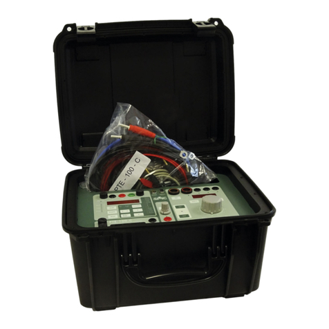
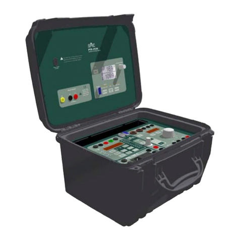
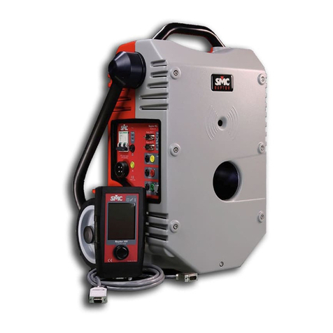
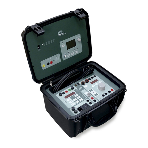
SMC Networks mentor 12 User manual


MENTOR 12 USER’S MANUAL SECTION 1: PRODUCT INTRODUCTION – Page 2
MENTOR 12 USER’S MANUAL
REFERENCE: JAAVMV02
VERSION 1 – NOVEMBER 2006 – COPYRIGHT EUROSMC, S.A.
ALL RIGHTS RESERVED.
DISCLAIMER The information contained in this document is intended only to describe the
product MENTOR 12 and its operation. This document has no contractual
contents and implies no warranty about the product’s specifications.
EuroSMC, S.A. claims the right to change the characteristics of the product and
the contents of this document with no previous announcement.
The user of the product is the only responsible of any consequences from the use
of the product for the purposes described or not in this document.
EuroSMC, S.A. explicitly exonerate themselves from the responsibility of any
errors accidentally made in this document.
Copying, reproducing or in any other way publishing this document in whole or in
part is prohibited without written authorization from EuroSMC, S.A.
The only official version of this document is the version written in Spanish
language


MENTOR 12 USER’S MANUAL SECTION 1: PRODUCT INTRODUCTION – Page 4
INDEX
Safety considerations....................................................................................8
Package’s contents.......................................................................................9
Handling the Mentor 12...............................................................................10
Transport case........................................................................................10
Working position.....................................................................................11
Product description .....................................................................................11
Start-up process..........................................................................................12
Start-up process..........................................................................................13
Initial check .................................................................................................15
Quick Start ..................................................................................................17
Power output control and regulation.......................................................17
Monitoring the binary input.....................................................................18
Binary output control...............................................................................18
Battery simulator setup and control........................................................19
Measuring external quantities.................................................................20
SECTION 2: BASIC CONTROL 21
Introduction .................................................................................................21
Description of source controls.....................................................................23
Selection of an output value........................................................................24
Selection of one single source (INDEPENDENT mode) ........................25

MENTOR 12 USER’S MANUAL SECTION 1: PRODUCT INTRODUCTION – Page 5
Simultaneous selection in several sources (SELECTED mode)............25
Selection when there are more than 3 available sources. ZOOM key. ..26
Application and Use of the function and help keys .....................................26
“Select all” key........................................................................................27
“Reset Values” key.................................................................................27
“Rotate” key............................................................................................28
“Save” and “Rest.” keys..........................................................................28
“Config. Status 2” and “Status 2” keys........................................................30
Measurement Window ................................................................................32
Configure times...........................................................................................33
TIMER START conditions ......................................................................34
TIMER STOP conditions ........................................................................36
TIMER Activation....................................................................................36
TIME DELAY..........................................................................................37
Configure measurements............................................................................38
System alarms ............................................................................................41
Battery Simulator.........................................................................................43
Logger.........................................................................................................44
SECTION 3: ADVANCED CONTROL 45
Introduction .................................................................................................45
FAULT Function..........................................................................................49

MENTOR 12 USER’S MANUAL SECTION 1: PRODUCT INTRODUCTION – Page 6
Configuration..........................................................................................53
Execution................................................................................................54
RAMP Function...........................................................................................57
Configuration..........................................................................................58
Execution................................................................................................63
PULSE RAMP function ...............................................................................65
Configuration..........................................................................................66
Execution................................................................................................71
BINARY SEARCH Function........................................................................73
Configuration..........................................................................................75
Execution................................................................................................79
STATE SEQUENCER function...................................................................81
Configuration..........................................................................................82
Execution................................................................................................84
SECTION 4: CONFIGURATION 87
Introduction .................................................................................................87
Common Configuration Operations.............................................................88
Analog Outputs ...........................................................................................89
Power Outputs. Definitions.....................................................................90
Usage Procedure....................................................................................91
Power Output Configuration...................................................................92
Configuration of the Low Level Outputs .................................................92

MENTOR 12 USER’S MANUAL SECTION 1: PRODUCT INTRODUCTION – Page 7
Binary Outputs ............................................................................................94
Definitions...............................................................................................94
Usage Procedure....................................................................................95
Binary Inputs...............................................................................................96
Definitions...............................................................................................96
Usage Procedure....................................................................................97
Miscellaneous .............................................................................................99
Definitions and Use ..............................................................................100
Maintenance..............................................................................................103
Definitions and Use ..............................................................................103

MENTOR 12 USER’S MANUAL SECTION 1: PRODUCT INTRODUCTION – Page 8
Safety considerations
Do not operate this product before carefully reading and understanding this manual, especially the safety
warnings and recommendations. The use of this equipment is reserved to trained personnel only.
DANGER: Never try to use a Mentor 12 that looks damaged, dirty or incomplete. Connecting the unit to a power supply with any
or all of its case’s faces removed is extremely dangerous.
DANGER: If you notice lack of response from the control panel, switch the unit off immediately and refer to technical service.
Otherwise, the power outputs could be left inadvertently activated.
DANGER: Harmful voltage can build up at the unit’s output connectors. Keep this in mind when handling the test leads and other
devices connected to them. Never introduce a non-isolated conductive tool or instrument into the unit’s connectors while the unit is
powered on or connected to the power supply.
CAUTION: Turn the unit ON before cabling anything to the connection’s board. Most input and output connectors in this board are
dynamic and feature self-protecting mechanisms that work only in if the Mentor 12 is powered on. Internal damage may result from
connecting the unit to wrong points when it is powered OFF.
CAUTION: Ensure that your power supply’s characteristics match the product’s supply requirements (voltage 100-260 Vac and
frequency 45-65 Hz) before connection. Use only the supplied power cord to an AC outlet that includes a good EARTH connection.
CAUTION: The equipment should only be serviced after adequate anti-static measures and procedures have been carried out.
WARNING: Keep the ventilation holes clear from any obstruction to avoid over-heating.
WARNING: Use only your finger or a soft pointer to operate the touch panel. Avoid excessive pressures on the touch panel. A
subtle touch should immediately activate the desired action. Do not use abrasive or alcohol-based substances to clean the touch
panel. Use only a soft, lint-free tissue or a special cleaning product for touch panels.

MENTOR 12 USER’S MANUAL SECTION 1: PRODUCT INTRODUCTION – Page 9
Package’s contents
Quantity Description
1 Mentor 12 unit, with variable power output channel configuration
1 Power Cord
1 Set of test leads in a nylon bag
1 Twisted-pair ETHERNET LAN cable
1 External mouse / keyboard PS/2 cord
1 User’s documentation
1 Certificate of calibration
1 Transportation hard case with wheels
NOTE: Contents may differ from the product’s standard packaging when
ordered with custom-specific options. If this is the case, refer to the
packing list included in the product’s shipping documentation.

MENTOR 12 USER’S MANUAL SECTION 1: PRODUCT INTRODUCTION – Page 10
Handling the Mentor 12
The Mentor 12 has been designed with ergonomics in mind to provide a safe,
convenient and reliable operation.
Transport case
Use always the supplied transport case for long displacements. This will save you
useless efforts and will avoid accidental damages to the unit. The transport case
features wheels and an extensible handle for your convenience.
Rest the case flat on the ground before opening it.
CAUTION: Do not grab the unit by the touch panel. Slide one hand into the slot underneath the touch panel and grab the back of
the unit with the other hand to lift the unit off the case onto the working surface. Another slot can be found behind the touch panel.
The test leads are packaged in a nylon bag inside the transport case. Re-package them
always when you finish working.
Stick FRAGILE labels on the transport case for long distance shipment.
Avoid strong impact and vibration to the unit even when kept in
the transport case.
Use always the transport case and include all the accessories
when sending the unit for servicing or calibration.

MENTOR 12 USER’S MANUAL SECTION 1: PRODUCT INTRODUCTION – Page 11
Working position
The Mentor 12 can stand up in two positions to better adapt to your work environment.
Both ways take up very little from your working surface. The standard position is
designed for a tabletop. Normally, you will not need to make any adjustment in the
touch panel orientation when using this position. Ventilation to the unit and access to
the connections are optimal in this position.
If you prefer to lay the Mentor 12 on the floor, stand it over the back side, where the
ventilation holes are found. Ensure that the surface is flat, hard and clean. Do not
operate the unit on soft carpets, cushioned or similar types of surface that can block the
normal ventilation air flow. Sand or excessive dust can get into the unit and cause
serious ventilation problems in the long term. You will need to adjust the touch panel’s
orientation when using the Mentor 12 in this position.
Product description
The Mentor 12 has been designed to make relay testing as easy, safe and efficient as
possible. The built-in computer eliminates the need of buying, carrying, connecting and
maintaining an external PC. This approach provides also stronger security against
operation mistakes and viruses. Yet, the Mentor 12 takes advantage of the best things
that are now common in the personal computing world: Plug & Play, graphical interface,
USB compatibility and access to the Internet, to say a few.

MENTOR 12 USER’S MANUAL SECTION 1: PRODUCT INTRODUCTION – Page 12
Touch Screen TFT
panel (swivel)
Adjustment knob
Handle
Main FUSE
BATTERY simulator
Power VOLTAGE outputs
Power CURRENT outputs
COMMUNICATIONS set
GPS antenna plug
Analogue MEASUREMENT
BINARY INPUT
BINARY OUTPUT
ETHERNET RJ-45 plug
GROUND connector
Power STATUS LED
Main ON/OFF switch

MENTOR 12 USER’S MANUAL SECTION 1: PRODUCT INTRODUCTION – Page 13
Start-up process
Before connecting any other device to the connections panel, plug the Mentor 12 into a
suitable AC supply using the supplied AC cord and switch the unit ON. Various start-up
screenshots will be displayed, with the TFT panel going occasionally black for a short
while: this is normal. The start up process takes less than 2 minutes and includes:
•General hardware check
•Embedded PC start up test & initialization
•Specific hardware check
•Mentor Application start up
Upon completion of the start up process, the Basic Control screen will give you a
general glance of the standard Mentor 12’s characteristics:
CAUTION: Ensure that your power supply’s characteristics match the product’s supply requirements (voltage 100-260 Vac and
frequency 45-65 Hz) before connection. Use only the supplied power cord to an AC outlet that includes a good EARTH connection.

MENTOR 12 USER’S MANUAL SECTION 1: PRODUCT INTRODUCTION – Page 14
Out
p
ut source selection area
Out
p
ut source
p
hase an
g
le
Out
p
ut source level dis
p
la
y
Out
p
ut source level ran
g
e & fre
q
uenc
y
bus
Out
p
ut source ON/OFF
Batter
y
Simulator setu
p
area
Measurements window
Binar
y
Out
p
ut ON/OFF buttons
Batter
y
Simulator DC settin
g
Batter
y
Simulator ON/OFF
Binar
y
In
p
ut Monitorin
g

MENTOR 12 USER’S MANUAL SECTION 1: PRODUCT INTRODUCTION – Page 15
You can now proceed to set up the control and power requirements for your test, and to
carry out the appropriate connections to the tested object (relay, IED, transducer, etc.).
You will find detailed directions how to configure the Mentor 12’s power and control
logic in the Configuration section in this manual.
When you finish your work, proceed to disconnect the test leads from the Mentor 12
first, then from the test objects. In this way you will prevent any voltage from
accidentally touching the surrounding objects or yourself.
You can then turn the unit off directly. No software shutdown procedure is required.
Initial check
We recommend you to carry out a general check on your particular unit, in order to
confirm that it has been configured properly according to your specifications. This will
take you less than 5 minutes:
NOTE: The procedures below assume that the Mentor 12 is in its initial
power-on state, i.e., no changes have been made to the default
factory settings.
•OUTPUT AMPLIFIERS CONFIGURATION: The initial factory-defined layout
shows three voltage sources at the upper half and three current sources at
the lower half of the Basic Control screen. Their default presets are: 63.5 V
for the voltage sources, 1 A for the current sources and 0º-240º-120º for the
angles.
Power sources are represented by colored (red, yellow, blue) rectangles
labelled Vs# for voltage and Cs# for current.
DANGER: Harmful voltage can build up at the unit’s output connectors. Keep this in mind when handling the test leads and other
devices connected to them. Never introduce a non-isolated conductive tool or instrument into the unit’s connectors while the unit is
powered on or connected to the power supply.

MENTOR 12 USER’S MANUAL SECTION 1: PRODUCT INTRODUCTION – Page 16
However, this basic layout does not represent the maximum output
capabilities of your Mentor 12. By means of the Configuration menu, you can
add the following to the standard power layout:
a) any combination of up to SIX current-mode or voltage-mode LOW
LEVEL SOURCES, regardless to the number of power channels that
you have ordered, or
b) any combination of up to SIX sources taken from the standard low-
level outputs and from any number of additional voltage or current
AMPLIFIERS that you may have purchased with you Mentor 12.
Please refer to the Configuration section in this manual to find out how to
locate, set up and include all your available output resources into the effective
power layout of your particular unit.
•FREQUENCY: Each power source is attached to any of two frequency buses,
Freq1 being the default assignment. Actual frequency bus #1 and #2 settings
are displayed and adjusted at a small window next to the sources section,
underneath the phasorial power system representation. Be sure that the
frequency bus(es) you are using match the electrical characteristics of the
system that you are testing.
Any change made to a frequency bus is automatically taken by all the sources
attached to it.
•ALARMS: The ALARMS indicator should be always dim (grey) after power-
on. Otherwise, touch the indicator to bring the alarm details up and refer to
the corresponding section in this manual for information on alarm
interpretation, possible causes and solutions.
•BATTERY SIMULATOR: The pre-adjusted DC voltage is shown in the
corresponding rectangle on the lower right. Touch and hold on the Battery
Simulator label to select a different voltage level if required.

MENTOR 12 USER’S MANUAL SECTION 1: PRODUCT INTRODUCTION – Page 17
Quick Start
You can quickly become familiar with your Mentor 12 by conducting a simple routine
through some basic manual operation functions:
•TFT panel operation
•Power output and regulation
•Binary input and output ports
•Battery simulator
•Analogue external measurement
To accomplish this, you will need at least the following materials:
•Multimeter
•One pair of test leads
Power output control and regulation
Choose one of the available current channels and try the following:
1. Adjust all the current channels to zero and be sure that the output is OFF.
2. Set up your meter and connect its current measurement input to the output
connector of a current channel.
3. Select the channel in the touch screen and turn the regulation knob gently
clockwise while you observe the meter’s display. Compare this display with
the regulated value of that channel in the Mentor 12.

M TEN R SECTION 1: PRODUCT INTRODUCTION – Page 18O 12 USER’S MANUAL
4. At a certain point, check the output control by touching the channel’s OFF
button in the Mentor 12 and then back ON. While you do this, check that the
meter’s output goes to zero and back to the adjusted quantity
correspondingly.
5. Turn the channel’s output OFF by touching its OFF button in the touch panel.
Now, set up your meter for voltage measurement and repeat the above procedure for
the voltage channels.
Monitoring the binary input
The Mentor 12 is permanently monitoring the presence / absence of contact or voltage
signal at its binary inputs. You can experience this easily:
1. Take one test lead and connect one end to the black connector between the
“1a” and “1b” yellow connectors in the Binary Inputs pad of the connections
board.
2. Connect the free end of the test lead to “1a”. The corresponding indicator
labelled “1a in” in the lower section of the Basic Control screen should lit in
yellow.
3. Move the same end of the test lead to “1b”. The “1b in” indicator should lit in
yellow now.
Binary output control
Set up your meter for continuity testing, so it will beep when you short its test leads.
Now, perform the following steps:
1. Connect the meter’s leads between the black and blue connectors of binary
output 1 in the Binary Outputs pad of the connections board.

MENTOR 12 USER’S MANUAL SECTION 1: PRODUCT INTRODUCTION – Page 19
2. Touch the Out 1 button of the Binary Output pad in the lower right corner of
the touch panel. The meter should beep until you touch the button again to
deactivate the output.
IMPORTANT: Instead of using the meter, you may want to connect the binary
output to a binary input as described in the previous procedure. In
this case, you will get a visual feedback in the touch panel rather
than a sound signal from the meter.
Battery simulator setup and control
The procedure here is similar to checking the voltage power outputs described at the
beginning of this chapter. However, rather than regulation, you can select the battery
simulator’s DC output voltage from a set of predefined values in the range of 0-250 Vdc.
Set up your meter for DC measurement, connect its leads to the Battery Simulator pad
in the connections board, and do the following:
1. Touch the ON button in the Battery Simulator pad at the bottom right corner of
the touch panel and check that the voltage displayed there is now being
measured by the meter.
2. Switch to a different DC value by touching the Battery Simulator pad (not the
ON/OFF button) for a few seconds and selecting from the emerging window.
When you do this, the battery simulator’s output is automatically stopped, so
you should see zero in your meter’s display now.
3. Repeat steps 1 and 2 if you want to check other available DC output values in
the battery simulator.

MENTOR 12 USER’S MANUAL SECTION 1: PRODUCT INTRODUCTION – Page 20
Measuring external quantities
Unless you also have an external source of electrical quantities, you can use the low-
level signal generation and regulation resources in your Mentor 12 to accomplish this
practice:
1. Ensure that all the power sources (voltage and current) are set to zero level
and the output control is switched OFF.
2. Plug one of the supplied multi-lead adapters into one of the connectors
labelled LL Outs 1-3 or 1-6 at the lower left section of the connections board.
3. Choose one red / black pair of bananas at the free end of the adapter and
plug them into the red / black connectors at the Analog DC Inputs pad.
4. Set the measurements window in the Basic Control screen to External
Measurement mode by touching the measurement readings as many times
as necessary.
5. Configure the connected low level output as a source using the Configuration
menus.
6. Select the added low level source in the Basic Control screen and turn the
adjustment knob while you watch the readings changing at the Measurements
window. Values at this window and at the source’s pad should match if you
have set a 1:1 ratio for the low-level source configuration.
Table of contents
Other SMC Networks Test Equipment manuals