SMC Networks PTE-50-CE Pro User manual

SINGLE PHASE RELAY TEST EQUIPMENT
User’s Manual
PTE-50-CE Pro
REFERENCE: FAFVMV02PR
EDITION: DECEMBER 2017
VERSION: 2
PTE-50-CE Pro
2
Quality is the core reference for EuroSMC’s activities, aimed to fully satisfy our
customers’ needs and expectations.
DISCLAIMER
The information, product specifications, and technical data contained in this
document imply no contractual binding to EuroSMC’s responsibility. The user is the
sole responsible for the application of the products mentioned in this document.
EuroSMC explicitly exonerates itself from liability to accidents or unwanted results,
directly or indirectly derived from mistakes made in the writing of this document.
Copying or reproducing all or part of this document is not allowed without the
explicit written permission from EuroSMC. Due to continuing development and
quality improvements, EuroSMC reserves the right to make changes in their products
without notice.

Operation Manual
3
INDEX
PACKING LIST ....................................................................... 5
1. INTRODUCTION............................................................... 7
1.1. MAIN FUNCTIONAL FEATURES ......................................................8
1.2. APPLICATIONS...............................................................................9
2. OPERATIONAL PRINCIPLE ................................................ 12
2.1. GENERAL .................................................................................... 12
2.2. FRONT PANEL CONTROLS ......................................................... 12
2.3. INTELLIGENT GENERATOR MODULE .......................................... 14
2.4. POWER SUPPLY........................................................................... 14
3. CONTROLS DESCRIPTION .............................................. 15
3.2. TIMER SECTION: CHRONOMETER............................................. 18
3.3. POWER OUTPUTS....................................................................... 23
3.4. POWER OUTPUT APPLICATION .................................................. 34
3.5. CONTROL SECTION .................................................................. 37
4. USE AND DESCRIPTIONS................................................. 43
4.1. TIME MEASUREMENT .................................................................. 43
4.2. LEVEL SELECTION: POWER OUTPUT ........................................... 45
4.3. PHASE ANGLE SECTION ............................................................. 49
4.4. GENERAL CONTROL SECTION................................................... 52
4.5. COMUNICATIONS IN THE BUS-PTE............................................ 53
4.6. SPECIAL FUNCTIONS.................................................................. 54
5. SPECIFICATIONS............................................................. 56
5.1. POWER GENERATORS ................................................................ 56
5.2. INTERNAL TIMER ......................................................................... 57
5.3. HARMONICS GENERATOR ......................................................... 58
PTE-50-CE Pro
4
5.4. EXTERNAL REFERENCE INPUT ...................................................... 58
5.5. SIGNAL MONITORS .................................................................... 58
5.6. AVAILABLE REFERENCES .............................................................. 59
5.7. CASE........................................................................................... 59
6. THE PTE-FCN VOLTAGE MODULE ................................... 60
6.1. DESCRIPTION.............................................................................. 60
7. AFTER SALES SERVICE AND WARRANTY ............................ 67
7.1. WARRANTY ................................................................................. 67
7.2. CUSTOMER SUPPORT ................................................................. 67
7.3. OTHER EUROSMC PRODUCTS.................................................... 67

Operation Manual
5
PACKING LIST
1 Unit PTE-50-CE.
1 PTE-FCN module1
1 Nylon cover.
1 Voltage supply cable type Schuko.
4 Interconnection cables 2.5 mm2 section (2 red and 2 black).
2 Interconnection cables 6 mm2 section (1 red and 1 black).
1 Interconnection cable between PC and PTE-50-CE unit, by RS-232.
1 PTE BUS interconnection cable for two units.
1 Interconnection cable for external timer output PTE-50-CE type BNC.
2 Clips up to 50 A (1 red and 1 black).
4 Clips up to 10 A (2 red and 2 black).
Replacement fuses:
4 Fuses 5x20 100 mA, fast.
2 Fuses 5x20 500 mA.
4 Fuses 5x20 6.3 A, fast.
1 Warranty.
1 Measurement Certificate.
1 Instructions Manual.
1Refer to the PTE-FCN VOLTAGE MODULE section at the end of this handbook for
details and operation instructions of this add-on.
PTE-50-CE Pro
6
Module PTE-FCN
1
PTE-FCN Unit
1
AC supply cord
2
Connection cables (1 black, 1 red)
1
Earth wire connection Cable
1
BUS-PTE interconnection Cable
2
5 x 20 mm, 0,75 A Fuses
1
European 0,5 A, FAST Fuse
2
European 1 A, FAST Fuses
2
European 1,25 A, FAST Fuses

Operation Manual
7
1. INTRODUCTION
The PTE-50-CE is designed as a Portable Single phase unit that allows the user
to test, as stand alone unit or in combination with others, all type of protective
relays.
Extremely compact and rugged, this unit incorporates the latest in the modern
microprocessor technology to achieve unbeatable output characteristics in terms
of power, accuracy, low distortion, and dynamic capability. This technology
allows the unit to perform, without any external accessories, various specific
functions very often used in the relay testing.
All the output signals are digitally generated, amplified and controlled by the
internal IGMs (Intelligent Generation Modules) in terms of amplitude, phase and
frequency. A high accuracy and stability are obtained in the output waveforms,
which are absolutely independent of the main supply.
Contained in an aluminum IP-65 case, with a membrane keyboard that allows
full manual control, and a RS-232 com port for computer control, the PTE-50-
CE offers the best features actually available for on site manual or automatic
relay testing.
PTE-50-CE Pro
8
1.1. MAIN FUNCTIONAL FEATURES
The following are the more outstanding functions/features that the PTE-50-CE
has:
a) TIMER MEASUREMENT
Used when measuring the timing response of relays during test. The digital timer
which is incorporated in the PTE-50-CE has a resolution of 1 ms and contains
all the necessary controls to select the starting and stopping of the timer whether
it is external or internal, or when using the monitor signal or via PTE-BUS.
b) AVAILABLE REFERENCES
The power output has three different references available:
oThe main supply phase (Line).
oThe PTE BUS (BUS).
oThe External Phase Reference (current or voltage).
c) POWER OUTPUTS
The current or voltage outputs are available, up to 50 A in four ranges and up
to 150 V in two ranges respectively.
All the outputs have a dynamic capability. The output regulation can work
independently or linked in a three phase system, when PTE units are working
together interconnected through the PTE BUS, any combination of dynamic steps
to 2nd values, can be selected in amplitudes and phase angles for any type of
fault simulation.
d) EXTERNAL REFERENCES INPUT
Can be synchronized, in terms of frequency and phase with any external signal,
from 0.1 to 25 A in current, and from 5 to 300 V in voltage.
e) SIGNAL MONITOR
The unit has a Signal Monitor input that can work with dry contacts or with
voltage signals from 5 to 250 V ac or dc.

Operation Manual
9
f) RS-232 COM PORT
Used to control the equipment from an external computer, can be used to
perform the following:
oSoftware calibration.
oAutomatic testing.
g) PTE BUS
Allows the interconnection with any other unit of the PTE RANGE.
h) EXTERNAL TIMER CONTROL OUTPUT
Delivers a pulse signal, dry contact type, of 20 ms duration. This can be used to
start an external timer, for timing measurements. This signal is produced every
time one of the power outputs changes its status, or the Step key is activated in
amplitude or in phase.
i) OUTPUT PROTECTION
The outputs and, in general, the unit, are electronically protected against
overload, short-circuit and over temperature. These alarms are indicated on the
Front Panel.
1.2. APPLICATIONS
AS STAND ALONE TESTING UNIT:
oSynchronizing relays.
oMultifunction generator protection Relays.
oHarmonics relays.
oOver current relays (up to 50 A).
oInverse time over current relays.
oDefinite time over current relays.
oEarth and neutral (including harmonics filtering).
oVoltage controlled relays.
oDirectional relays.
oDifferential relays.
PTE-50-CE Pro
10
oSingle phase distance relays.
oDirectional power relays (single and three phase).
oMaximum and minimum voltage relays.
oDynamic test. Fault simulation.
COMBINED WITH A SINGLE OR THREE PHASE CURRENT OR VOLTAGE
INJECTOR:
oThree phase distance relays.
oIn general all types of relays which require 3 voltages and 3 currents to
function correctly.
MISCELLANEOUS:
Due to its good characteristics of accuracy and stability, the PTE-50-CE can test
transducers, energy meters and measuring instruments can be tested as well, in
the following ranges:
oSingle phase current up to 50 A
oSingle phase voltage up to 150 V.
oHarmonic selection, 7th harmonic.
oPhase angle from 0º to 359.9º.

Operation Manual
11
Figure 1: Front Panel of the PTE-50-CE
PTE-50-CE Pro
12
2. OPERATIONAL PRINCIPLE
2.1. GENERAL
In this section a general overview of the operational basic principles on which
the PTE-50-CE is based, are given in this section.
The PTE-50-CE unit has 3 main functional independent blocks, they are:
oFront Panel.
oIntelligent Generator Modules (IGM).
oPower Supply.
2.2. FRONT PANEL CONTROLS
Allows the user to communicate with the power output section of the unit in a
manual way, or using a software program. To achieve this, it has the following
sections:
Displays and LED indicators: indicate the various selections made by the
operator and the status of the unit:
oPress key controls: this is a membrane keyboard with acoustic
feedback, in which the various different functions available in the unit
are selected.
oMulti-turn control knobs: these are rotative pulse generators that are
used to make the different selections desired on the displays indicators,
in an easy and fast manner.
oMonitor taps: contain the circuits to detect the status of the signals
applied in these taps

Operation Manual
13
Figure 2: Front Panel Block
oExternal Reference Taps: contains the circuits to synchronize the power
outputs to the phase and frequency signals connected to these taps.
oCommunications: the PTE units have the capability to communicate
with some external control devices by RS-232 (allowing the user for
printing results and calibration from the PC) and by BUS-PTE, for
interconnection with PTE RANGE units and control of these by a
computer.
oInternal Bus Interface: establishes the communication between the
Front Panel and the Intelligent Generator Module, via the
microprocessors included in both.
oTime Generator: it generates the high accuracy time reference
necessary to generate the internal phase and frequency.
oOutput taps: these are the taps of the auxiliary voltage supply of 110 V
ac, the power output taps, and the tap to start an external timer.
oMicrocontroller: it is one of the most important parts of the unit, which
as its name indicates, controls or establishes the flow of information
between all the functional blocks previously mentioned.
PTE-50-CE Pro
14
2.3. INTELLIGENT GENERATOR MODULE
Essentially, the IGM is a linear power amplifier, controlled by its internal
microprocessor. It produces the sinusoidal signal in the frequency and the phase
selected. This is amplified and adapted by a transformer in the selected output
range. This generator also feedback’s the output level in voltage, current, and
phase, to the generation stage, thus achieving a high accuracy output.
As shown in the block drawing and in the front panel control functions, a
microprocessor is in charge of supervising all the functions of the generator
modules. They receive the output measurements and make the corrections
necessary in amplitude and phase to obtain the desired accuracy. Also they
store the calibration parameters, and use them to correct the selections made
from the Front Panel.
Figure 3: Intelligent Generator Module
2.4. POWER SUPPLY
This groups contains the transformers and switching power supplies which supply
and energizes the front panel block and IGM.

Operation Manual
15
3. CONTROLS DESCRIPTION
This section describes one by one and in detail all of the controls, indicators,
displays, and connection taps on the front panel of the PTE-50-CE. As well as
the functions, marked indications and where they are located will be shown in
the figures.
To understand this clearly, sections will describe the controls, by sections, their
physical position on the front panel. The different types of controls that you can
find are classified as follows:
oKEY CONTROLS: this refers to the press key and rotating knobs. The
description is of the use and where they are located.
oDISPLAY AND VISUAL INDICATORS: this refers to the LED indicators
and the selection displays. The description is of the use and where
they are located.
oCONNECTORS (TAPS): this refers to all taps (input and output),
connectors, etc., which are contained in the PTE-50-CE.
oThis section describes all the connectors that are incorporated in the
unit. All of them meet international safety standards and are easily
identified with their corresponding identification marks on the front
panel.
PTE-50-CE Pro
16
3.1. MAIN SUPPLY SECTION
3.1.1. MAIN VOLTAGE SUPPLY
The unit is supplied with SCHUKO type plug 2 poles with earth.
Also incorporated in the connector is a filter to avoid perturbations from the
main supply.
Figure 4: Voltage supply Connector
This is situated on the bottom left hand side of the unit and includes the
following:
oPower supply with 2 poles and earth.
oPower supply fuse holder: to reach these fuses, the cover must be lifted
as indicated in the drawing.
oThere are two fuses: the lower one is the active fuse and the one
located above is the spare fuse.
The fuse is a standard 5 x 20mm, normal fuse with a value of 2 A. (For
equipment of a voltage supply of 230V. For equipment using a voltage supply of
115V the fuse value is 4 A.)
oPower supply switch: it has 2 positions, ON/OFF. The unit is
disconnected when the red mark of the switch is visible.

Operation Manual
17
FIXED 110 V c.a. VOLTAGE SUPPLY
This output is located in the lower central section to the right of the power supply
switch. It consists of 2 black, 4 mm taps.
This output is always active when the unit is switched on. The taps have a
distance of 19 mm which is the standard two-pole plug size.
ACTIVE
FUSE
PTE-50-CE Pro
18
3.2. TIMER SECTION: CHRONOMETER
The Timer is located on the left-hand side of the unit and clearly marked from
the rest of the unit. It contains all the necessary controls for various timing
functions, which are explained below.
Figure 5: Timer Section

Operation Manual
19
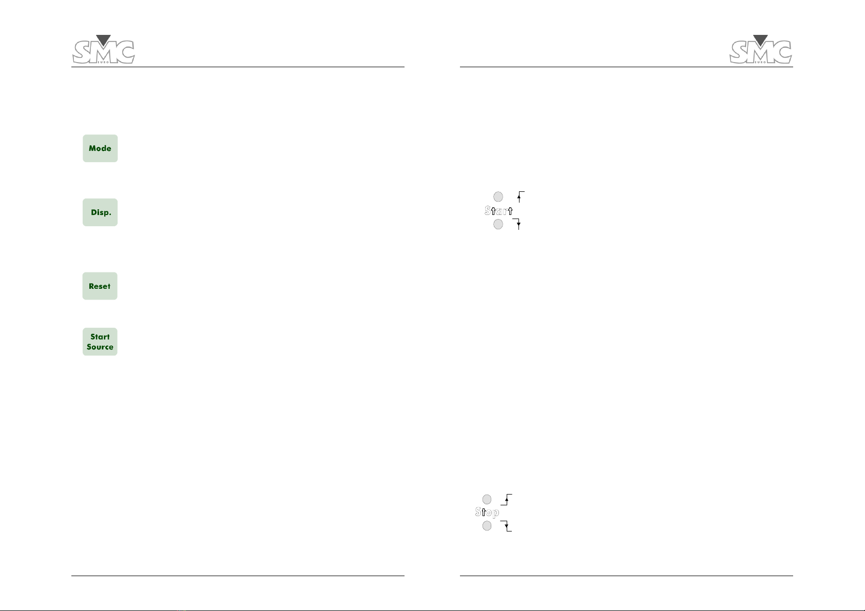
3.2.1. CONTROL KEYS AND KNOBS: Selecting the function mode
This section describes how to select the timer mode for the starting/stopping of
the timer, the timer reading, and how to reset it. The keyboard for the timer is as
follows:
This key works in a sequential way, that is to say by pressing
this key; the LED’s will indicate the different selection
combinations. There are 6 different possibilities to choose
from, see 3.2.2.
This key works in a sequential way, each time this key is
pressed, the reading in Display 1 located on the left-hand side
will change. This will display seconds or the number of
frequency cycles in alternating current.
Each time this key is pressed the timer will reset to 0, allowing
the operator to perform the next test. If the timer is not reset,
all the outputs and displays will remain on hold and blocked.
This key allows the selection of the Timer whether it is internal
or external. Each time this key is pressed the selection will
change from one to another. There are 2 VISUAL LED’s
associated with this key.
PTE-50-CE Pro
20
3.2.2. VISUAL INDICATORS AND DISPLAYS
oFunction mode indication
There are 6 green LED’s of 3 mm. When these are lit they indicate
mode function the equipment has. These LEDs are associated with the
Mode key:
a) START Mode indicators:
These 2 LEDs indicate the start mode of the Timer in
relation to the output control ON/OFF and to the 2nd Value
Step press key. These 2 LEDs are 3 mm and green. Only
one can be used at the same time:
When the upper LED is lit, it indicates that the Timer will start when:
oThe output control is activated (ON)
oWhen there is a Step to 2nd Value.
oWhen a contact is closed at the input of the external timer.
oWhen this LED is flashing it indicates that the Timer is in BUS mode,
meaning that it will start when there is a positive event in the BUS.
When the lower LED is lit, it indicates that the Timer will start when:
oThe output control is deactivated (OFF)
oWhen a Step to 2nd Value is deactivated.
oWhen a contact is open at the input of the external timer.
When this LED is flashing it indicates that the Timer is in BUS mode, meaning
that it will start when there is a negative event in the BUS.
b) Stop Mode Indicators
These 2 LEDs indicate the stop mode of the Timer in relation
to the Monitor state. These 2 LEDs are 3 mm and green.
Only one can be active at the same time .

Operation Manual
21
oWhen the upper LED is lit, it indicates that the Timer will stop when the
Signal Monitor is activated. When this LED is flashing it indicates that
the Timer is in BUS mode, meaning that the Timer will stop when there
is a positive event in the BUS.
oWhen the lower LED is lit, it indicates that the Timer will stop when the
Signal Monitor is deactivated.
oWhen this LED is flashing it indicates that the Timer is in BUS mode,
meaning that the Timer will stop when there is a negative event in the
BUS.
They are controlled by the MODE key.
a) PULSE Mode Indicators
These 2 LEDs indicate the Timer is in the PULSE
MEASUREMENT MODE, and whether the pulse is positive
or negative. These pulses are measured through the Signal
Monitor taps .These 2 LEDs are green and 3 mm. Only one
can be active at the same time.
oWhen the upper LED is lit, it indicates the Timer will read an active or
positive pulse measurement.
oWhen the lower LED is lit, it indicates the Timer will read a non-active or
negative pulse measurement.
Both of these LEDs are controlled by the Mode key and can only be active
when the Timer is in the EXTERNAL Mode.
oTIMER SIGNAL indicators
These are two green and 3mm LEDs. Only one can be
active at the same time
When the Int. LED is lit, the timer will start /stop with internal signals from
the unit, such as:.
PTE-50-CE Pro
22
oActivating ON/OFF in any channel.
oActivating a Step to 2nd Value in any channel.
When the EXT LED is lit, the start signals are produced externally, and
introduced in the Monitor 2 located above the Timer display. At the same
time the Timer should be set in the PULSE mode in Monitor 1.
oTimer Display
The timer reading has 5 digit, 7 segment LEDs and 0.3 inches in height. There
are two possible readings. On the right hand side they are 3 indicators that
indicate the timed reading. They are:
oS: time in SECONDS
oCy: indicates the NUMBER OF FREQUENCY CYCLES IN
ALTERNATING CURRENT.
The Timer display can only make 1 stop and start event, and cannot be used
again until the Reset key is pressed.
3.2.3. CONNECTORS: Monitor Signal
This BNC connector is associated with a 3 mm, yellow LED.
This input allows only a dry contact, voltage free. When the
input is closed the LED will light up indicating the Monitor is
active.

Operation Manual
23
3.3. POWER OUTPUTS
The equipment has an output and phase channels. In each one of them can be
selected the desired output level as well as the phase angle.
This section is situated in the central section of the unit, and is clearly identified.
All the controls, indicators, etc. contained in this part of the unit will be
explained .
3.3.1. OUTPUT SECTION
Figure 6: Selection of the OUTPUTS
PTE-50-CE Pro
24
oCONTROL KNOBS AND PRESS KEYS
a) Selecting the digit to be used.
This key works in a sequential way and it is associated with 3
LEDs located above this press key. This allows the operator
to select the output in a fine or course regulation, by
changing the digit to be adjusted.
The following resolutions can be obtained:
o1 digit.
o10 digits.
o100 digits.
When pressing this key for more than 2 seconds, it will block the rotating pulse
generator, not allowing any modifications to the level selected
b) Rotating Control Knob
This is a rotating pulse generator and has step by step
sensation. The values can be increased or decreased by
turning this control knob clockwise or anti-c clockwise by
one digit per step, according to the selected digit weight as
described previously. This knob has no end and can be
controlled at any speed. However if the control knob is
turned very fast the value will change at a maximum rate of
1 digit per second.
However if the control knob is turned very fast the value will change at a
maximum rate of 1 digit per second.
c) Output Selection ON/OFF
When this key is pressed the output will turn on and the LED
situated below will light up.
When it is pressed again it will disconnect this output and
the LED will be off.

Operation Manual
25
d) Selecting the 2nd value
When this key is pressed it allows the selection of a 2nd value
and it is shown in the display. This selection does not cancel
the value already selected in the output at the moment. To
distinguish the actual value from the 2nd value selected, the
LED over the key lit when the 2nd value is displayed.
e) Activating the 2nd value
This key works in a sequential way. When pressed the output
value changes to the 2nd value, when it is pressed again it will
return to the 1st value.
When this key and the similar key in the phase section are pressed at the same
time for more than 2 seconds this function if both sections becomes
synchronized. To cancel you must repeat this process.
PTE-50-CE Pro
26
f) Selecting the output range and output selection
This key has two function modes:
oCurrent:
0 - 0.33 A
0 - 8 A
0 - 25 A
0 - 50 A
oVoltage:
0 - 6.25 V
0 - 150 V
This key is associated with the 4 red LEDs with the ranges marked and the
display in this section
1. Selection of the output type: this key serves to select the output type
desired, that is voltage (V) or current (I). When turning on the unit it will be
in current output. To change this output to voltage you must press this key
for more than 2 seconds. To change this output back to current, repeat the
process.
2. Output range selection: this key also serves to select the output range, in
voltage and current. This key works in a sequential way: each time it is
pressed it will change the output range. There are 2 ranges in voltage and
4 ranges in current. They are:

Operation Manual
27
oVISUAL AND DISPLAY INDICATORS
a) LED Indicator for 2nd Value selection
This is a 3 mm, red LED that is situated over the
corresponding key. When this LED is lit, it indicates that it is
in the 2nd Value Selection mode and that this value is shown
in the display..
b) LED indicator when 2nd value is activated.
This is a 3 mm, red LED that is situated over its
corresponding press key. It has two states:
oNot lit: indicates that the phase angle in the output is the first value
oLit: indicates that the phase angle in the output has changed
To the second value.
c) LED Indicator when the 2nd value is activated
This is a 3 mm, red LED that is situated below its
corresponding press key. It has two states:
oNot lit: indicates that the output is (OFF)
oLit: indicates that the output is (ON)
This LED is also associated with the OUTPUT ON/OFF. In whichever case the
LED shows the REAL STATE of the output. It also can be controlled internally by
the equipment (E.g.: Alarm).
d) Digit selection Indicators
PTE-50-CE Pro
28
These three, 3 mm LEDs (red), indicate the digit selection for
regulation. Only one will be lit and it indicates the digit
above it to be regulated. These are situated above the press
key.
e) Level selection display
The display is made up of 4 digits of 7
segments, red in color and 0.3 inches in
height, which shows the selected values
and the corresponding units to the
selected parameter with three indicators
located to the right side of the display.
There are two different parameters available:
ocurrent (A).
ovoltage (V)
In current and voltage, depending on the selected range, the decimal point will
adjust automatically. The V and A indicators will light up automatically when
selected.
When the value in the display begins to flash, it indicates that the value selected
and is not in the output.
f) Output range selection indicators
There are four red LEDs of 3 mm located
below the output taps. These indicate the
selected output range, in both voltage or
current.

Operation Manual
29
To selected the desired output current or voltage, is made by pressing the TAP
I/V key
g) Alarm Indicators
There are two, 3 mm LEDs (red) which
indicate the status of the two alarms for the
output of PTE-50-CE.
They are as follows:
oOvl: this LED indicates an overload in the output, whether it is
current or voltage. When it is lit, the output will cut off and the display will
begin to flash for 5 seconds. During this time it is possible to reset the
output by pressing the ON/OFF button.
oTh: this LED indicates an internal thermal overload, (temperature
overload). When this alarm is on, the LED will light up, and the output
will cut off. While this LED is on it is not possible to work with the unit
and the operator must wait until the internal temperature lows.
When the thermal alarm is lit, turn off the unit for at
least 1/2 hour.
oTAPS: Output taps
These taps are situated in the upper
central part of the unit and consist of 3, 4
mm female connectors up to 50 A. The
first ones are used for the voltage and
current outputs and the
third one is used only for current, in the
50 A range. With the unit two testing
cables are supplied, which are used with
these taps.
PTE-50-CE Pro
30
3.3.2. PHASE ANGLE SECTION
This is situated to the right of the unit and is perfectly identified. It contains all the
control knobs, keys, and LEDs necessary for the operator to use the functions in
this section.
Figure 7: Phase Angle Selection

Operation Manual
31
oCONTROL KNOBS AND PRESS KEYS
a) selecting the digit to be used
This key works in a sequential way and it is associated with 3
LEDs located above this press key. This allows the operator to
select the output in a fine or course regulation, by changing
the digit to be adjusted.
The following resolutions can be obtained:
o1 digit.
o10 digits.
o100 digits.
When pressing this key for more than 2 seconds, it will block the rotating pulse
generator, not allowing any modifications to the phase angle selected.
b) Rotating control knob
This is a rotating pulse generator and has step by step
sensation. The values can be increased or decreased by
turning this control knob clockwise or anti-clockwise by one
digit per step, according to the selected digit weight as
described previously. This knob has no end and can be
controlled at any speed.
However if the control knob is turned very fast the value will change at a
maximum rate of 1 digit per second.
c) 2nd value selection
When this key is pressed it allows the selection of a 2nd phase
angle and it is shown in the display. This selection does not
cancel the angle already selected in the output at the
moment. To distinguish the actual angle from the 2nd value
selected, the LED over the key lit when the 2nd value is
displayed.
PTE-50-CE Pro
32
d) Activating 2nd value
This key works in a sequential way. When pressed the phase
angle in the output changes to the 2nd value, when it is
pressed again it will return to the 1st value.
When this key and the similar key in the phase section are
pressed at the same time for more than 2 seconds this
function if both sections becomes synchronized. To cancel you
must repeat this process.
oVISUAL INDICATORS Y DISPLAY
a) LED Indicator for the 2nd value selection
This is a 3 mm, red LED that is situated over the corresponding key.
When this LED is lit, it indicates that it is in the 2nd Value Selection mode
and that this value is shown in the display.
b) LED Indicator when the 2nd value is activated
This is a 3 mm, red LED that is situated over its corresponding press
key. It has two states:
oNot lit: indicates that the phase angle in the output is the first
value
oLit: indicates that the phase angle in the output has changed
to the second value.
c) Digit selection indicator
These three, 3 mm LEDs (red), indicate the digit selection for
regulation. Only one will be lit and it indicates the digit above it to be
regulated.
d) Phase selection Display
The display is made up of 4 digits of 7 segments, red in
color and 0.3 nches in height, which shows the
selected values.

Operation Manual
33
oINPUT TAPS
a) External reference input taps
These taps are situated in the upper
right hand side of the unit and
consist of 3 female taps, 4mm
diameter, which allow input up to
25 A.
These Taps are to receive an external reference to the equipment in frequency
or phase, which enables the PTE-50-CE to be referenced to them. These taps
admit two types of signals:
oVoltage: Connected between the black tap (0) and the red tap (5-
300V). Input levels between 5V and 300V and frequency between 40
and 200 Hz are admitted
oCurrent: Connected between the black tap (0) and the green
(0.1-25 A). Input levels between 0.1 and 25A 5V and 300V
and frequency between 40 and 70 Hz are admitted.
Extreme care must be taken not to connect voltage in
the current taps, as these inputs are of low impedance
(shunt) and can cause damage to outside voltage
source by short circuit.
PTE-50-CE Pro
34
3.4. POWER OUTPUT APPLICATION
3.4.1. Use
Taking note that the output channel, of PTE-50-CE, can supply a maximum of
100 VA.. This means that the output tap we have a voltage value that cannot be
exceeded:
Tap Maximum voltage
0.33 A 150 V
8 A Booster OFF 6.25 V
Booster ON 12.5 V
25 A Booster OFF 2 V
Booster ON 4 V
50 A Booster OFF 1 V
Booster ON 2 V
In fact, the only electrical parameter with a real physical sense, by itself, is
voltage. We cannot define a current supply in terms of current capacity only, but
we need to define the maximum load that can be connected to the taps, to
reach the current limit.
Suppose we have the burden of a relay (15 VA) at the nominal current (5 A). We
can calculate its internal impedance using the Ohm’s Law:
VALOAD = ILOAD VLOAD VLOAD = VALOAD / ILOAD = 15/5 = 3 V
ZLOAD = VLOAD / ILOAD = 3/5 = 0.6 A
This means that if you want to inject 5 A in this relay a 3 V voltage is needed, so
a 15 VA power from the injection equipment.

Operation Manual
35
3.4.2. CONNECTING IN PARALLEL WITH OTHER EQUIPMENT
If we want to connect various PTE-50-CE outputs to obtain a higher output in
parallel, it is necessary that the outputs are connected as shown below:
A
V
A
V
A
V
Relay Input Relay Input
Equip`ment 1 Equipment 2 Equipment 3
Figure 8: Connecting in parallel various PTE-50-CE units
Remember that the current outputs, to be added correctly, must have the same
phase angle, for instance:
We can select the same or different levels in the outputs but, to achieve the
maximum power, we recommend to use them with the same levels (for instance,
if we want to inject 60 A, we would set 20 A in each channel).
PTE-50-CE Pro
36
To use the three power outputs as one, we will select the Master-Slave-Slave
configuration, and then we just have to turn the channel 1 output on.
Note: Of course, we can connect only two channels. It will depend on the power
required.
3.4.3. EXAMPLE
Suppose we want to inject 65 A to a relay using the three channels in parallel.
After making the connections, we will select:
CH1 Amplitude: 22 A Phase angle: 0.0º
CH2 Amplitude: 22 A Phase angle: 0.0º
CH3 Amplitude: 21 A Phase angle: 0.0º
Now we can have 300 VA as maximum, so the current we can get from the
equipment will depend on the connected load. As we don’t know this
impedance load of the relay, we will calculate the maximum load that can be
connected to the taps injecting 65 A:
VAOUTPUT = IOUTPUT VOUTPUT
ZLOAD = VOUTPUT/ IOUTPUT VAOUTPUT = IOUTPUT
2ZLOAD
Then if we are looking for the maximum load at 65 A:
ZMAXIMUM LOAD = VAMAXIMUM OUTPUT / IOUTPUT
2 = 300/652= 0.071
If we connect a relay with higher impedance than 0.071 (considering PTE-50-
CET as an ideal generator), it will be an overload for the PTE-50-CET. The
equipment will stop the injection, indicating the Overload Alarm.

Operation Manual
37
3.5. CONTROL SECTION
This part of the equipment refers to the general control. The unit contains several
necessary controls to perform the following functions:
oUsing RS-232.
oSYNCHRONIZE selection.
oHARMONICS selection.
oBOOSTER activation.
oEVENT Output.
oMonitor signals.
Figure 9: General Control Section
3.5.1. CONTROL KEYS
oBOOSTER / RS-232
This press key has 2 functions, they are:
PTE-50-CE Pro
38
a) Activating the BOOSTER mode:
The BOOSTER key has two modes, ACTIVATED and
DEACTIVATED. When the unit is turned on is in the
DEACTIVATED mode. When it is activated, the maximum
voltage is double in each output range. This function is
automatically deactivated if it is not necessary. When the
Booster is activated the LED marked B will be lit.
b) RS-232 Serial Port Control
This press key controls the RS-232 COM port activation to
communicate the unit to a PC. Continue to press the key until
the LED above this key indicates it is active.
oHARMONIC Selection Control
The press key is marked Harm. This key enables to select the
fundamental frequency reference desired.
A
s other press keys, each time one of these keys is pressed the
harmonic will change up to the 7th harmonic, so you can
select: 1st, 2nd, 3rd, 4th, 5th, 6th and 7th.
oMASTER/SLAVE Key
The press key marked Master/Slave. This key enables to select
the function of each equipment connected via the Each time the
key is pressed the following can be selected
oIndependent. The equipment when first turned on and in a
normal state is in independent mode, and does not affect
any equipment connected via the BUS PTE. The 2 LEDs
associated with this key are not lit.
oMaster. When the equipment is selected as the Master is the
unit that controls the system. The indicator LED, Mo will be
lit. There can only be one unit selected as the Master.
Changes and control setting made on the Master unit will
be reflected in the units, which are in the Slave mode.

Operation Manual
39
oSlave. When the equipment is selected in the Slave mode, is
controlled by the unit selected as Master, and changes and
controls are taken from the Master unit. Changes made in
the slave do not affect other units even when connected via
the BUS
oSYNCHRONIZING CONTROL KEY
This key controls the different references available in the
PTE-50-CE. Each time this key is pressed a different
synchronized reference is selected.
3.5.2. VISUAL INDICATORS
RS-232 port indicator
This is a 3 mm LED (red). When it lit, indicates that the serial
port RS-232 is active so it can send or receive information
BOOSTER mode Indicator
This is a 3 mm LED (red)., marked with B. When it lit, indicates
that the Booster is active.
SYNCHRONIZING REFERENCE indicators
They are three, 3 mm red leds. Only one is on at the same
time.
oLine: the reference is the main voltage supply.
PTE-50-CE Pro
40
oBus: the reference is another PTE unit connected via BUS-
PTE. Normally the PTE-300-V or PTE-100-V. If the led is
flashing there is no reference in the BUS.
oExt: the selected reference is taken from another instrument
or equipment connected in the external reference tap. If the
led is flashing there is no valid reference.
MASTER/SLAVE mode Indicators
These are 2, 3 mm green and red LEDs. One green and the
other red. Only one LED can be lit at the same time or when
in independent mode neither are lit.
M: The equipment is in Master mode
S: The equipment is in Slave mode
Both Unlit: The equipment is in independent mode
Monitor state indicator
This is a 3 mm red LED, located above the Monitor taps.
When it is on, indicates that the Monitor is ACTIVATED.
When it is off, indicates the Monitor is DEACTIVATED.
3.5.3. CONNECTORS and FUSES
oVoltage supply
PTE-50-CE has channel fuses that protects the Power Module. These fuses can
be broken in different circumstances (like high transients in the outputs).
When this happens, one of the power outputs half-cycle is lost. That’s why the
values you check in you ammeter differ from the ones displayed in the
equipment.
This manual suits for next models
1
Table of contents
Other SMC Networks Test Equipment manuals