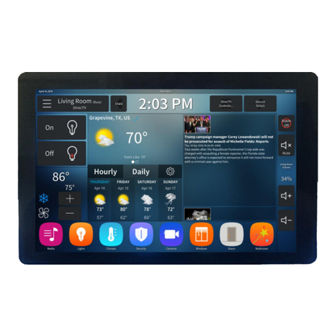
SMC Networks RB5701-Z User manual

uControl User Guide
TouchScreen
PN: 631-00008-01 Rev 1.0
August 17, 2010

Page ii | August 17, 2010
© 2006, 2007, 2008, 2009, 2010 uControl, Inc. The uControl logo, uControl, Inc., and all other uControl products and technology names are trademarks or
registered trademarks of uControl, Inc. All other products or services mentioned herein are trademarks of their respective companies.
Compliances
FCC Notice
This device has been designed, constructed, and tested with for compliance with FCC Rules that regulate
intentional and unintentional radiators. As the user of this device, you are not permitted to make any
alterations or modifications to this equipment or to use it in any way that is inconsistent with the
information described in this quick-start guide, without the express written permission of SMC
Networks. Doing so will void your warranty to operate this equipment.
This device complies with Part 15 of the FCC rules. Operation of this device is subject to the following
two conditions:
1. This device may not cause harmful interference, and
2. This device must accept any interference received, including interference that may cause undesired
operation.
The ―IC‖ designation preceding the radio certification number indicates that this device complies with
the Industry of Canada specifications.
Device Purpose
Fire/Alarm Central Panel
UL1023 Notice
This device complies with UL1023.

Page iii | August 17, 2010
UL985 Notice
This device complies with UL985.
UL1635 Notice
This device complies with UL1635.
ULC S545 Notice
This device complies with ULC S545.
UL985 Notice
This device complies with ULC C1023.
ETL Notice
This device complies with all ETL and ETLC safety requirements.
Limitations of Security Products
Security products and alarm systems do not offer guaranteed protection against burglary, fire, or other
emergencies. They may fail to warn for diverse reasons, including (but not limited to): power failure,
dead batteries, improper installation, coverage , coverage areas overlooked during installation, defeat by
technically sophisticated intruders, component failure, or inadequate maintenance. Alarm systems should
be checked weekly to ensure that all devices are working properly.
AN ALARM SYSTEM IS NOT A SUBSTITUTE FOR INSURANCE.

Page iv | August 17, 2010
Table of Contents
WELCOME TO THE TOUCHSCREEN ........................................................................................................ 1
UNDERSTANDING SECURITY NETWORK COMPONENTS...................................................................................... 2
UNDERSTANDING THE SECURITY ZONE TYPES .................................................................................................... 3
UNDERSTANDING ALARMS......................................................................................................................................... 4
CONFIGURING THE TOUCHSCREEN ......................................................................................................................... 5
SUBSCRIBER PORTAL .................................................................................................................................................... 6
USING THE TOUCHSCREEN..................................................................................................................... 7
UNDERSTANDING THE TOUCHSCREEN CONTROLS.............................................................................................. 7
LOW POWER MODE...................................................................................................................................................... 9
UNDERSTANDING THE SCREEN...............................................................................................................................10
CONTENT AREA ......................................................................................................................................................11
HOME SCREEN .....................................................................................................................................................11
WIDGETS ...............................................................................................................................................................11
SECURITY STATUS HEADER...............................................................................................................................12
SYSTEM &ZONE TROUBLE HEADER ..............................................................................................................12
MANAGING YOUR SYSTEM SECURITY.....................................................................................................16
UNDERSTANDING ARMING MODES .......................................................................................................................16
ARM AWAY MODE...................................................................................................................................................16
ARM STAY MODE ....................................................................................................................................................18
ARM NIGHT MODE .................................................................................................................................................19
ARMING AND DISARMING THE SYSTEM.................................................................................................................20
DISARMING THE SYSTEM....................................................................................................................................... 20
ARMING THE SYSTEM ............................................................................................................................................. 23
CANCELLING THE ARMING PROCESS..............................................................................................................25
QUICKARMING THE SYSTEM .............................................................................................................................26
SENDING A EMERGENCY ALARM ............................................................................................................................27
PROTECTION AGAINST SMASH &GRAB.................................................................................................................28
MANAGING SENSORS .................................................................................................................................................29
DISABLE A SENSOR ................................................................................................................................................. 29
VIEWING YOUR ZONE EVENT HISTORY ...........................................................................................................30
CHANGING THE ORDER THAT SECURITY ZONES ARE LISTED IN THE TOUCHSCREEN...........................31
MANAGING CAMERAS................................................................................................................................................32
TESTING YOUR ALARMS............................................................................................................................................ 34
MANAGING CONNECTIVITY BETWEEN THE TOUCHSCREEN AND THE CENTRAL MONITORING
STATIONS ......................................................................................................................................................................39
VIEWING SIGNAL STRENGTH ...............................................................................................................................39
TESTING YOUR CONNECTIVITY .......................................................................................................................... 39
CONFIGURING A NEW OR RESET SECURITY NETWORK ROUTER TO WORK WITHIN THE SECURITY
NETWORK.................................................................................................................................................................41
MANAGING CONNECTIVITY BETWEEN YOUR HOME DEVICES AND THE INTERNET................................. 44
MANAGING THE PASSCODES IN YOUR SECURITY SYSTEM .................................................................................50
MANAGING YOUR KEYPAD CODES.....................................................................................................................50
UNDERSTANDING THE DURESS KEYPAD CODE ..........................................................................................52
MANAGING YOUR SECRET WORD.......................................................................................................................53
VIEW YOUR SECURITY ACCOUNT INFORMATION................................................................................................53

Page v | August 17, 2010
MAINTAINING AND CONFIGURING THE TOUCHSCREEN DEVICE ....................................................... 54
REBOOT THE TOUCHSCREEN...................................................................................................................................54
CONFIGURING THE SCREEN BRIGHTNESS SETTINGS .........................................................................................55
CONFIGURING THE SCREENSAVER .........................................................................................................................57
CONFIGURING THE TONES AND VOLUME LEVELS .............................................................................................57
CLEANING THE TOUCHSCREEN SCREEN............................................................................................................... 58
VIEWING TECHNICAL SPECIFICATIONS OF YOUR TOUCHSCREEN ..................................................................59
APPENDIX A: USING THE KEY PAD........................................................................................................ 60
CHECKING SYSTEM STATUS...................................................................................................................................... 60
ARMING THE SYSTEM................................................................................................................................................. 60
ARM AWAY MODE...................................................................................................................................................61
ARM STAY..................................................................................................................................................................61
DISARMING THE SYSTEM........................................................................................................................................... 61
SENDING AN EMERGENCY POLICE ALARM ..........................................................................................................61
MOUNTING THE KEY PAD........................................................................................................................................ 62
CHANGING THE BATTERIES IN THE KEY PAD .....................................................................................................62
APPENDIX B: USING THE KEY FOB ....................................................................................................... 63
CHECKING SYSTEM STATUS...................................................................................................................................... 63
ARMING THE SYSTEM................................................................................................................................................. 64
ARM AWAY MODE...................................................................................................................................................64
ARM STAY..................................................................................................................................................................64
DISARMING THE SYSTEM........................................................................................................................................... 64
SENDING AN EMERGENCY POLICE ALARM ..........................................................................................................65
CHANGING THE BATTERIES IN THE KEY FOB......................................................................................................65
APPENDIX C: DEVICE INSTALLATION AND MAINTENANCE ................................................................. 66
BATTERY REQUIREMENTS.........................................................................................................................................66
INSTALLATION INFORMATION.................................................................................................................................67
TOUCHSCREEN INSTALLATION OPTIONS..........................................................................................................67
POSITIONING THE TOUCHSCREEN ON A FLAT SURFACE ...........................................................................67
MOUNTING THE TOUCHSCREEN ON THE WALL MOUNT...........................................................................69
RECOMMENDATIONS FOR SENSOR INSTALLATION AND PLACEMENT ........................................................73
DOOR/WINDOW SENSORS AND GLASS BREAK DETECTORS..................................................................... 73
GLASS BREAK DETECTORS................................................................................................................................73
MOTION DETECTORS .........................................................................................................................................74
SMOKE DETECTOR INSTALLATION RECOMMENDATIONS .........................................................................75
CAMERA INSTALLATION RECOMMENDATIONS............................................................................................. 76
SYSTEM LIMITATIONS ................................................................................................................................................76
EMERGENCY PREPARATION..................................................................................................................................... 77
APPENDIX D: QUICK REFERENCE TABLES ........................................................................................... 78

Welcome to the TouchScreen
Page 1 | August 17, 2010
Welcome to the TouchScreen
The purpose of this document is to explain how to do the following:
Arm and disarm your security system
View system status and arm/disarm the system
Manage passcodes
Manage security zones
Manage emergency dispatch contact information
Manage alerts
Manage contacts
View history logs
View account information
Figure 1: Security Network

Welcome to the TouchScreen
Page 2 | August 17, 2010
Understanding Security Network Components
Table 1 describes the equipment included with your security system.
Table 1: Security Network Components
Component
Description
TouchScreen
The device used to interface with your security system.
A/C Adapter
Provides power to the TouchScreen from an outlet in your secured premises
Sensors
Doorway/
window
Monitors the opening and closing of potential entry and exit
points
Motion (indoor)
Monitors movement within the premises
Cameras (indoor)
Up to six cameras can be installed in your security system. Cameras can be
configured to take a series of pictures if a particular sensor is faulted.
Security Network
Router
The hub of your security network. This device is installed between your broadband
modem and your home network router.

Welcome to the TouchScreen
Page 3 | August 17, 2010
Understanding the Security Zone Types
Security zones are the sensors that detect movement and the opening and closing of doors and
windows. The sensors communicate wirelessly with your TouchScreen. Security zones are added to
the system and configured by your installer. You can enable and disable each security zone using the
Security widget.
Table 2: Security Zone Types
Security Zone
Function
Description
Sensor Types
Note: For more information on Entry/Exit delays, see Understanding Arming Modes on page 16.
Entry/exit
For doorways that are used to enter the premises.
When the system is armed, faulting this type of sensor starts an
Entry Delay countdown rather than sending an immediate alarm.
During Exit Delay, this zone can be repeatedly faulted.
Doorways can be configured to be entry/exit or non-entry/exit.
Door/Window
Perimeter
If faulted when the system is armed or during an Entry/Exit
delay, an alarm is tripped.
Door/Window sensor
Motion detector
Glass Break detector
Interior
Follower
Monitors the internal living spaces of the premises and trigger an
immediate alarm if the system is armed in Away mode;
Not armed when the system is in Armed Stay mode;
Motion detector
24-Hour Inform
When this security zone is tripped, there is never an alarm, but an
event is recorded in the history and the TouchScreen makes a
configured sound.
Door/Window sensor
Motion detector
Glass Break detector
24-Hour Fire
Generates an immediate fire alarm if triggered
Smoke alarm

Welcome to the TouchScreen
Page 4 | August 17, 2010
Understanding Alarms
When an alarm is tripped an audible alert is sounded. From that point, you have a specific amount of
time (default: 30 seconds) to enter your keypad code or an alarm will sound. If a valid keypad code is
not entered within a specific time (default: 30 seconds) of the audible alarm sounding, a message is
sent to a central monitoring station. The central monitoring station will attempt to contact the
persons listed on the account. When they reach a person listed on the account, they will ask for the
Secret Word and affirm whether a genuine emergency is occurring. If no one on the list can be
contacted, or if the person contacted gives the wrong Secret Word, the central monitoring station
immediately dispatches police or other appropriate emergency personnel.
If the alarm is not cleared within 4 minutes, the system resets so it can monitor additional alarm
events.
If a sensor is faulted too many times resulting in alarms, no more alarms will be sent to central
monitoring for 48 hours or until the security system is disarmed.

Welcome to the TouchScreen
Page 5 | August 17, 2010
Configuring the TouchScreen
Your TouchScreen’s default settings are configured from the Settings widget.
To access the Settings widget:
1. From the Home screen (see page 11) touch the Settings widget.
The Keypad screen is displayed.
2. Touch the numbers to enter your keypad code.
The Settings menu is displayed.
From the Settings Widget you do the following:
Manage the Quickarm settings (page 26)
Manage the way sensors are listed in TouchScreen reports and tools (page 30)
Manage your cameras (page 32)
Test your alarms (page 34)
View and test the TouchScreen’s connectivity to the central monitoring stations (page 34)
Manage your keypad codes and secret word (page 50)
View your account information (page 53)
Manage your TouchScreen device sounds, screensaver, etc. (page 54)
View technical information about your TouchScreen device (page 59)

Welcome to the TouchScreen
Page 6 | August 17, 2010
Subscriber Portal
The Subscriber Portal is a web-based tool that allows you to remotely connect to your security
system. You can access the Subscriber Portal from a PC or mobile Internet device. Many operations
that can be done from the TouchScreen can also be performed from the Subscriber Portal. Some
operations such as managing which widgets are accessible from your TouchScreen can only be
performed from the Subscriber Portal.
Your installer has provided you with the URL address of the Subscriber Portal as well as a username
and password to access it.

Using the TouchScreen
Page 7 | August 17, 2010
Using the TouchScreen
Understanding the TouchScreen Controls
Figure 2: TouchScreen Device & Home Screen

Using the TouchScreen
Page 8 | August 17, 2010
Table 3: TouchScreen Controls
Component
Description
More Information
Screen
Interfaces with your security system
See page 10
Home button
Press this button to go to the Home screen in the
TouchScreen screen.
The button is located at the bottom center in front
of the device.
See Figure 2
Quickarm button
Press this button to start the Quickarm function.
The button is located at the bottom left in front of
device.
When A/C power is available, this button is lit.
See page 26
Panic button
Press this button to manually and immediately send
an alarm to the appropriate call center.
The button is located at the bottom right in front of
the device.
When A/C power is available, this button is lit.
See page 27

Using the TouchScreen
Page 9 | August 17, 2010
Low Power Mode
The TouchScreen is powered by a back-up battery and A/C power. When A/C power is lost, the
TouchScreen places itself in Low Power Mode (LPM).
In LPM the following occurs:
The screen goes dark.
The Quickarm button LED and the Panic button LED goes dark.
The TouchScreen stops communicating with the central monitoring station and the
uControl servers over broadband.
The TouchScreen sends an alert over cellular to the uControl servers that the system is in
LPM.
The TouchScreen stays awake only enough to continue communicating with the sensors and
monitoring for other events.
When the screen is touched, the TouchScreen ―wakes up‖ temporarily, but you will not be able to
use widgets that need to communicate with remote sources. For example, you will not be able to use
the News widget or Photo widget at all.
When an event or alarm occurs, the TouchScreen wakes up only enough to send a notification to the
uControl servers.

Using the TouchScreen
Page 10 | August 17, 2010
Understanding the Screen
The TouchScreen screen is used to interface with your security system. It provides:
A real-time view of the system statuses
Tools to manage your security system
Additional optional applications
Table 4: TouchScreen Screen Elements
Component
Description
More
Information
Security Status
Header
Tells you whether the system is armed or disarmed and other
information. Touch this header to arm or disarm the system.
This element displays in the upper left corner of the TouchScreen
screen.
See page 12
System & Zone
Trouble Header
Only displays when there is a connectivity (cellular, broadband, etc.) or
power problem with the TouchScreen, when a sensor goes down (such
as due to a battery failure), or a sensor is being tampered with (such as
the cover being opened).
This element displays in the upper right corner of the TouchScreen
screen.
See page 12
Content Area
Home
Shows the widgets that have been installed to the system
See page 11
and Figure 2
Widgets
Select to access applications that extend the functionality of
TouchScreen
Security
Select the Security widget to view options related
arming/disarming the system, enabling/disabling security
zones, and viewing history logs recent security zone events
Settings
Select the Settings widget to access tools to modify the
TouchScreen configurations.
Cameras
Select the Cameras widget to view a live feed of all the
cameras in your security system.
Date/Time Bar
Displays the current date and time
Not applicable

Using the TouchScreen
Page 11 | August 17, 2010
Content Area
This area contains the interactive functionality of your TouchScreen. When you use or modify a
widget, this is where the tools and options are provided.
If the Content Area is black (showing nothing) this is because the system is not receiving A/C
power. The display is powered off to conserve battery life.
Home Screen
The Home screen is the default interface when the user accesses the TouchScreen screen. Return to
this screen at any time by pressing the Home button (center bottom of the TouchScreen).
Widgets
The widgets are applications that provide additional functionality through the TouchScreen. The
Security and Settings widgets are the only non-optional widgets. All other widgets can be enabled and
disabled from the Subscriber Portal. From the Subscriber Portal you can also do the following:
Reposition the order that widgets are displayed in the Content Area
Configure widgets that require it before being used
Note: Your updates will not be received at the TouchScreen if your device does not currently have
Internet access.

Using the TouchScreen
Page 12 | August 17, 2010
Security Status Header
The Security Status header displays in the upper left hand of the TouchScreen. It tells you whether
the system is armed or disarmed and other information. Touch this header to arm or disarm the
system.
During an alarm the Security Status header changes to show an Alarm state, such as ―ALARM |
OPEN –FRONT DOOR‖ or ―ALARM | MOTION – SEC ZONE 1‖.
Also, during troubles that would prevent arming (such as a monitored door or window being
opened) an announcement replaces the Arm/Disarm status. If you touch this header at that time, the
TouchScreen presents you will dialog to arm the system with the capability to turn off the problem
security zone.
During the Exit Delay, the header changes to announce ―ARMING IN <X> SECONDS‖ (where
<X> is the number of seconds before the system is armed).
During the Entry Delay, the header changes to announce ―ALARM IN <X> SECONDS‖ (where
<X> is the number of seconds before the system is armed).
System & Zone Trouble Header
The System & Zone Trouble header displays in the upper right hand of the TouchScreen. If only
displays when there is a connectivity (cellular, broadband, etc.) or power problem with the
TouchScreen, when a sensor goes down (such as due to a battery failure), or a sensor is being
tampered with (such as the cover being opened).
When a System & Zone header is displayed, click it to display the Troubles screen listing all current
troubles with TouchScreen and the sensors.
Table 5: System & Zone Trouble Header Messages
Component
Cause
Solution
AC Power Loss
TouchScreen is not receiving A/C
power.
The system is in Low Power Mode (see
page 9).
Confirm that the power adapter is
plugged into the TouchScreen.
Confirm that the power adapter is
plugged into an unswitched outlet.
Confirm that the unswitched outlet has
power.
Install the power adapter into another
outlet.

Using the TouchScreen
Page 13 | August 17, 2010
Table 5: System & Zone Trouble Header Messages
Component
Cause
Solution
Alarm communication
failed
TouchScreen is not accessing the
Internet through the local network, nor
does it have cellular connectivity.
Restore Internet connectivity as soon
as possible.
If the lack of cellular connectivity
persists, contact Customer Care.
Battery failure
Backup battery for the TouchScreen is
dead, and there is a loss of external
power.
After external power is restored, it takes
approximately 21 hours for the battery to
be fully charged.
When AC Power is restored the
battery will recharge. If not, have the
battery connection checked.
Battery Low
See Sensor Battery Low.
Confirm that the power adapter is
plugged into an unswitched outlet.
If A/C power is connected but has
been off for an extended period, the
battery could still be charging.
Battery Removed
Battery for the TouchScreen has become
detached
Open the battery cover and check the
battery connection.
Broadband connection
failed
TouchScreen is not accessing the
Internet through the local network, but
the device still has cellular connectivity.
Restore Internet connectivity as soon
as possible.
Cellular
communication failed
TouchScreen cannot communicate over
the cellular network.
If this problem persists, contact
Customer Care.
Communication
Jammed
TouchScreen has detected an attempt to
jam its communication with the sensors.
Most likely, someone is using a device
designed to scramble the radio frequency
(RF) signal of the sensors.
This could be a burglary in progress.
Lost Power
External power for the sensor or device
named in this alert is not connected.
Only applicable to devices that required
external power.
Restore power to the sensor or device
as soon as possible to avoid draining
the battery
Low Battery Detected
Battery for the identified sensor is low.
Replace the battery as soon as possible.
Needs Cleaning
Sensor named in this alert is dirty or
dusty
Clean the identified sensor

Using the TouchScreen
Page 14 | August 17, 2010
Table 5: System & Zone Trouble Header Messages
Component
Cause
Solution
Network connection
failed
No broadband or cellular connectivity to
the TouchScreen
Restore Internet connectivity as soon
as possible;
Contact Customer Care to report your
loss of cellular connectivity
Sensor Battery Low
Battery for the sensor named in this alert
is low. This is 2.75v for sensors and key
pads and 2.6v for key fobs.
Replace the battery as soon as possible
Sensor Communication
Failure
TouchScreen cannot communicate with
the identified sensor
Replace the battery
OR
Replace the sensor.
Sensor Communication
Jammed
TouchScreen’s communication with the
identified sensor is being jammed.
Most likely, someone is using a device
designed to scramble the radio frequency
(RF) signal of the sensors.
This could be a burglary in progress.
Sensor Lost Power
External power for the identified sensor
or device is not connected
Restore power to the sensor or device
as soon as possible to avoid draining
the battery
Sensor Needs Cleaning
Identified smoke detector is dirty or
dusty
Clean the identified smoke detector.
Sensor Tamper
Detected
Cover of the identified sensor has been
removed.
Check the identified sensor.
Sensor Test Button
Pressed
Test button for the identified sensor was
pressed
If a sensor test is not in progress,
check the identified sensor.
System Battery Low
TouchScreen has lost A/C power and is
on battery backup. The battery voltage is
3.7v, that is about 5% remaining power.
Complete loss of power to the
TouchScreen is imminent.
Check the A/C adapter.
Restore A/C power to the
TouchScreen as soon as possible.
System not ready to
Arm
Door or window is open.
Open the Security widget and check
the security zones, door or window
might be open
System Power Lost
TouchScreen has lost A/C power and is
on battery backup
Check the A/C adapter;
Restore A/C power to the
TouchScreen as soon as possible

Using the TouchScreen
Page 15 | August 17, 2010
Table 5: System & Zone Trouble Header Messages
Component
Cause
Solution
System Tampered
The back cover or battery cover of the
TouchScreen has been removed
Replace the cover as soon as possible.
System Upgrade in
Progress Message
Firmware update currently in progress
No action required;
Message will go away when the update
is completed.
System will not Arm
User entered an invalid keypad code
when attempting to arm the system
Reattempt to enter the security code.
Use the Settings widget to add, edit,
and delete keypad codes
Contact Customer Care.
Tamper Detected
Cover of the identified sensor or device
has been removed
Check the sensor or device.
Zone Swinger
Shutdown
A sensor has been too many times
resulting in alarms (default is one time).
No more alarms will be sent to central
monitoring for 48 hours or until the
security system is disarmed.
The Swinger Shutdown feature helps
prevent a runaway TouchScreen from
tying up the central station.
Disarm the system to stop the swinger
shutdown.
Contact customer care to find out the
maximum number of alarms sent to
central monitoring before swinger
shutdown for your system.
Other manuals for RB5701-Z
1
Table of contents
Other SMC Networks Touchscreen manuals