manuals.online logo
Brands
  1. Home
  2. •
  3. Brands
  4. •
  5. SMC Networks
  6. •
  7. Valve Positioner
  8. •
  9. SMC Networks Chryssafidis P8001 Series Manual

SMC Networks Chryssafidis P8001 Series Manual

!Depending on the parameter's setting, the actuator will move
erratically when an input current of 4mA DC is applied.
!There is a capacitor for noise prevention between FG terminal (case)
and each input / output terminal of the positioner respectively.
Therefore, avoid conducting withstand voltage testing or insulation
resistance testing between the terminal and case.
!Please refer to the Operation manual for further details.
2 INTENDED CONDITIONS OF USE
2.1 Specifications
Protect the unit from impact and dropping during installation and when
mounted. This may cause failure of the unit.
!Do not use the unit in places with high humidity & temperature.
This may cause malfunctions.
!Do not use this positioner outside of the range of it's specifications as
this can cause failure.
Table1 Specifications
*1: 1/2 split range is available using the split range setting (parameter
code: 300).
*2: <Ex.> When applying an input current of 80mA DC, an input power
supply voltage of 12.5V DC or less will prevent damage to the
positioner.
Max. supply power = 80mA DC×12.5V = 1W
*3: If the feedback lever assembled to the positioner rotating angle is 30°
or less, its stroke can be adjusted optionally in a range from 0 to 10°
and from 0 to 30°. Please set the operation angle of the feedback
lever to 10°when accuracy is required.
*4: Linearity is a characteristic checked without loads using a factory
inspection machine. The positioner can not work independently and is
used as a part of loop including actuating equipment such as a valve,
actuator and DCS. Therefore, it should be noted that the described
characteristic values may vary depending on the loop conditions.
*5: (ANR) indicates standard air in accordance with JIS B0120.
Table2 Specifications of options
*6: When no input current has been applied, an alarm is output. Fig. 1
shows an internal alarm circuit.
Read this manual before using this product
!The information within this document is to be used by pneumatically
trained personnel only.
!For future reference, please keep manual in a safe place.
!This manual should be read in conjunction with the current catalogue.
1 SAFETY RECOMMENDATION
1.1 General recommendation
These safety instructions are intended to prevent a hazardous situation
and/or equipment damage. These instructions indicate the level of
potential hazard by label of "Caution", "Warning" or "Danger".
To ensure safety of personnel and equipment the safety instructions in this
manual and the product catalogue must be observed, along with other
relevant safety practices.
WARNING:
•The compatibility of pneumatic equipment is the responsibility of a person
who designs the pneumatic system or decides its specification.
!Since the products specified here are used in various operating
conditions, their compatibility for the specific pneumatic system must
be based on specifications or after analysis and/or tests to meet your
specific requirements.
•Only trained personnel should operate pneumatically operated machinery
and equipment.
!Compressed air can be dangerous if an operator is unfamiliar with it.
Assembly, handling or repair of pneumatic systems should be
performed by trained and experienced operators.
•Do not service machinery/equipment or attempt to remove components until
safety is confirmed.
!Inspection and maintenance of machinery/equipment should only be
performed after confirmation of safe of dangerous fluid.
!When equipment is to be removed, confirm the safety process as
mentioned above. Switch off air and electrical supplies and exhaust all
residual compressed air in the system.
!Before machinery/ equipment is re-started, ensure all safety measures
to prevent sudden movement of cylinders etc. (Bleed air into the
system gradually to create backpressure, i.e. incorporate a soft-start
valve).
•Contact SMC if the product is to be used in any of the following conditions:
!Conditions and environments beyond the given specifications, or if
product is used outdoors.
!Installation on equipment in conjunction with atomic energy, railway,
air navigation, vehicles, medical equipment, food and beverages,
recreation equipment, emergency stop circuits, press applications, or
safety equipment.
!An application, which has the possibility of having negative effects on
people, property, or animals, requiring special safety analysis.
CAUTION:
!Ensure that the air supply system is filtered to 0.3 micron.
1.2 Specific recommendations
!If the input current is disconnected during use, the output of OUT1 will
become 0MPa and the output of OUT2 will reach its maximum,
regardless of the operating direction of the parameter mode
(parameter code: 200), whether direct or in reverse.
!If reverse operation is selected in parameter mode (parameter code:
200), when the power supply is turned off, OUT1 output will become
0MPa and the positioner will start moving toward input current
20mADC direction.
CAUTION: Operator error could result in injury or equipment damage.
WARNING: Operator error could result in serious injury or loss of life.
DANGER: In extreme conditions, there is a possible result of serious
injury or loss of life.
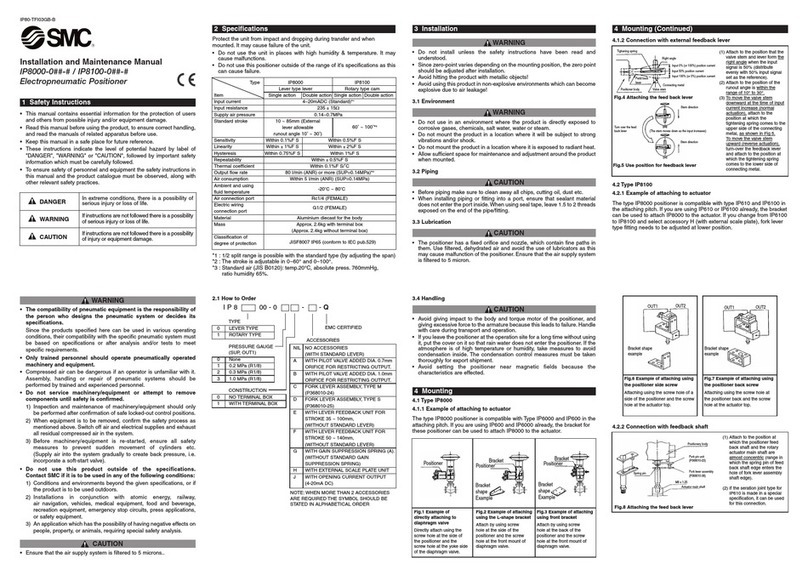
IP8001-TFL21GB
Installation and Maintenance Manual
Series IP8001 Smart Positioner (Lever type)
!
Model
Item IP8001-0**-*-*-Q
Input current 4㨪20mADC 㧖1㧔2 wire system,
Separate power source unnecessary㧕eromroCDAm58.3tnerrucmuminiM
Voltage between
terminals
12VDC
㧔Input resistance equivalent to 600Ω, at 20mADC㧕Max supply power 1W 㧖2㧔100mADC, 28VDC㧕Supply air pressure 0.14㨪0.7MPa
Standard stroke 10o㨪30o㧖3
Sensitivity ±0.2%F.S. or less 㧖4
Linearity ±1%F.S. or less 㧖4
sselro.S.F%5.0siseretsyH
sselro.S.F%5.0±ytilibataepeR
/.S.F%50.0tneiciffeocerutarepmeT oC or less
Max output flow rate 80 l/min(ANR) or more (SUP=0.14MPa)㧖5
2 l/min(ANR) or less (SUP=0.14MPa) 㧖5
Air consumption 4 l/min(ANR) or less (SUP=0.4MPa) 㧖5
Ambient and operating
fluid temperature -20oC to 80oC
Classification of degree
of Protection JIS F8007 IP65 (IEC 60529)
Communication
Protocol HART communication
Air connection ports Rc1/4 female thread (or G1/4 or 1/4NPT)
Electrical connections G1/2 female thread (or 1/2NPT or M20x1.5)
Body/Cover : Die cast aluminium
㧔Coating : Epoxy resin baked㧕Material
Shaft / Screw : Stainless
gk6.2xorppAthgieW
Model
Item IP8001-0*2-*-Q
Alarm output1, 2 㧖6
metsyseriw2dohtemgniriW
Power supply voltage 10㨪28VDC
Load current 10㨪40mADC 㧖7
Internal resistance 350Ω±10㧑sselroCDAm5.0egakaeltnerruC
sselrocesm05emitesnopseR
Analogue output 㧖8
metsyseriw2dohtemgniriW
Supply source voltage 10㨪28V DC
Output current 4㨪20mADC
Load resistance 0㨪750Ω
sselro.S.F%5.0±ycaruccA 㧖9
1 SAFETY RECOMMENDATION (CONTINUED) 㧙㧙㧖㨧㨩㧙㧙
708233C
CHRYSSAFIDIS S.A./ ATHENS: 3 AGRINIOU STR, TAVROS - (+30) 210 4836315-20 / THESSALONIKI: DA12A STR, OT32, BIPE SINDOU - (+30) 2310 754681-4 / www.chryssafidis.com / [email protected]
2 INTENDED CONDITIONS OF USE (CONTINUED)
*7: 10mADC or more load current is needed to operate the main circuit of
the internal switch, and it should be 40mADC or less to protect the
internal resistance circuit.
Therefore, use a power supply
voltage and load resistance with
a load current of 10 to 40mADC
when the output is on.
*8: Connect a load resistance with
consideration given to the
minimum power supply voltage.
*9: Analogue output accuracy to
position value (P value) in the
LCD display.
2.2 How to Order
*10: If two or more accessories are required, the part numbers should be
made according to alphabetical order.
3 INSTALLATION
WARNING:
!Do not install unless the safety instructions have been read and
understood.
!Avoid hitting the product with metallic objects.
!Avoid using this product in non-explosive environments which can
become explosive due to air leakage.
!If the system is in possible danger because of failure of the positioner,
prepare the system with an alternative safety circuit to avoid danger.
3.1 Environment
WARNING:
!Do not use in an environment where the product is exposed to corrosive
gas, chemicals, salt water, water or steam.
!Do not use in a location where there is danger of explosion.
!Do not mount the product in a location where it is subject to strong
vibrations and/or shock. When the positioner is used in places subject to
vibrations, it is recommended that a suitable cable support be used to
prevent the lead wires from breaking.
!Do not mount the product near the source of electrical noise.
!Do not mount the product in a location where it is exposed to radiant heat.
!Allow sufficient space for maintenance and adjustment around the
product when mounted.
3 INSTALLATION (CONTINUED)
3.2 Piping
CAUTION:
!Before piping make sure to clean up chips, cutting oil, dust etc.
!When installing piping or fitting into a port, ensure that sealant material
does not enter inside the port. When using seal tape, leave 1.5 to 2
threads exposed on the end of pipe / fitting.
!Use de-humidified and dust-removed clean air as the supplied air source.
!The Positioner has very fine internal paths. Therefore please use clean
air which is dehydrated and filtered, and also avoid using lubricant. In
addition, use a cleaning system according to No. 4 or higher from the
"!Compressed Air Cleaning Equipment" listed in the manual for the
air-supply cleaning systems.
!Avoid using compressed air containing chemicals, synthetic fluid including
organic solvent, salinity, and corrosive gas as it may cause malfunction.
3.3 Electrical connection
CAUTION:
!Be sure to perform electrical wiring with the input current turned off.
!Be sure to use a grounding to prevent noise from interrupting input
current and static electricity from damaging the positioner.
!Do not touch around the actuator axis when applying an input current
after electrical wiring.
!Use an input current source (4 to 20mA DC) with a secure 12V DC or
greater voltage as close as possible to the input current terminal to
avoid voltage drops.
3.4 Mounting
WARNING:
!Confirm the positioner is securely and firmly mounted onto the actuator.
!Be careful not to get fingers caught when matching mounting positions.
CAUTION:
!Be sure to keep the necessary space available for maintenance work
(piping, wiring, adjustment, etc.) in your setup location.
!Disconnect the supply pressure and ensure compressed air is discharged
from the positioner and actuator completely before starting mounting.
3.5 Lubrication
CAUTION:
!The positioner has a fixed orifice and nozzle, which contain fine internal
paths. Use filtered, dehydrated air and avoid the use of lubricants as
this may cause malfunction of the positioner. Ensure that the air supply
system is filtered to 0.3 micron.
3.6 Handling
CAUTION:
!Avoid applying impact to the body and torque motor of the positioner,
and avoid excessive force to the armature because it may lead to
failure. Handle with care during transportation and operation.
!If the positioner is left unused at the operation site for an extended
period, ensure the body cover unit is fitted, and mount a plug on the
wiring and piping ports. If the atmosphere is of high temperature or
high humidity, take measures to avoid condensation inside the
positioner. The condensation control measures must be taken
thoroughly during export shipment.
!Be sure to mount the body cover unit when using the positioner. IP 65
cannot be guaranteed if the mounting condition of the body cover is
incorrect. To achieve IP capability, tighten the screws with the
appropriate torque (2.8 to 3.0Nm).
㨪㧖㧔㧕㧔㧕㧖㧔㧕㨪㨪㧖㧖㧖㧖㧖㧖㧔㧕㧖㨪㨪㧖㧑㧖㨪㨪㨪㧖OUT(+)
OUT(-)
Main
circuit
switch
Fig. 1
I P 8 0 0 1㧙0 * *㧙Pressure gauge
1 0.2MPa
2 0.3MPa
3 1.0MPa
Type
001
Smart
Positioner
Lever Type
Accessory 㧖10
-seirosseccaoNLIN
EWith feedback lever unit
for stroke 35 to 100mm. Without standard lever.
FWith feedback lever unit
for stroke 50 to 140mm. Without standard lever.
W With body cover window. Without standard body
cover.
Construction
0 Standard type
2Output function
㨧analogue (4-20mADC)
output+ alarm output×2㨩3 HART communication function
Q
EMC CERTIFIED
*㧙*㧙Connections
Mark Air Electric
Nil Rc1/4 G1/2
M Rc1/4 M201.5
N Rc1/4 1/2NPT
1 1/4NPT G1/2
2 1/4NPT M201.5
3 1/4NPT 1/2NPT
4 G1/4 G1/2
5 G1/4 M201.5
6 G1/4 1/2NPT
IP8001-TFL21GB
4 WORKFLOW OF IP8001 POSITIONER SETUP
The workflow of IP8001 smart positioner from set-up to initial adjustment is
shown below. Follow this flow when performing set-ups and adjustments of
the positioner. Please refer to the manual for details.
5 MOUNTING
!Example of Mounting on Actuator
The IP8001 Smart Positioner offers interchangeability in mounting pitch with
the IP600, IP6000 and IP8000 Positioners. Therefore, it is possible to apply
a bracket for IP600, IP6000 and IP8000 for mounting.*11
5 MOUNTING (CONTINUED)
*11: There is a possibility that the connection and the feedback lever
interfere when the IP600 type is exchanged for the IP8001 type.
Please machine the connection or interpose the spacer between the
positioner and the bracket at that time.
*12: Do not impact on the feedback shaft of the positioner when the
feedback lever connected with the valve stem or installed in the
positioner.
*13: The installation direction of spring need not be changed by the
difference of the direction of operation unlike the IP8000 type.
6 PIPING
Table 3
Attach using the screw
holes at the rear of the
positioner and the screw
holes at the front mount
of the diaphragm valve.
Fig. 5
Directly attach using the
screw holes at the side
of the positioner and the
screw holes at the yoke
side of the diaphragm
valve.
Fig. 3
Attach using the screw
holes at the side of the
positioner and the screw
holes at the front mount
of the diaphragm valve.
Fig. 4
13
*
Connection of Feedback Lever 12
*
Fig. 6
(1) Attach the positioner so that the valve stem and feedback lever form
a right angle when the input current is 50% (distribute evenly with
50% input current set as the reference).
(2) Attach the positioner so that the operation angle of feedback lever is
within the range of 10°to 30°.

Fig. 2
7 ELECTRICAL WIRING
!Without Output Function (IP8001-030, IP8001-033)
(1) Remove the positioner body cover.
(2) Connect the input current wiring from an adjusting meter (controller)
following Fig. 7.
!With Output Function (IP8001-032)
(1) Remove the positioner body cover.
(2) Connect input current wiring from an adjusting meter (controller) and
each output wiring following Fig. 8.
8 DESCRIPTION OF COMPONENTS
9 MAINTENANCE
WARNING:
!Do not dis-assemble the product. A product which has been dis-
assembled cannot be guaranteed. Consult with SMC if dis-assembly is
necessary.
!After installation, repair and dis-assembly, connect compressed air and
perform a proper functional test and leak test. If bleed noise is louder
than the initial state or operation is abnormal, stop operation and check
if installation is correct or not.
CAUTION:
!Check if supply air is clean. Inspect compressed air cleaning system
periodically so that dust, oil and humidity, which can cause malfunction
and failure of the unit, do not enter the equipment.
!If handled improperly, compressed air can be dangerous. Maintenance
and replacement of unit parts should only be performed by trained and
experienced personnel for instrumentation equipment, as well as
following the product specifications.
9 MAINTENANCE (CONTINUED)
!Check the positioner once a year. If excessively worn diaphragms,
O-rings or seals are found, or any unit that has been damaged,
replace with new units. Treatment at an early stage is especially
important if the positioner is used in a place of severe environment like
coastal area.
!Before removing the positioner for maintenance or replacing unit parts
after installation, make sure the supply pressure is shut off and all
residual air pressure is released from piping.
!When the fixed orifice is clogged with carbon particles or others,
remove the pilot valve unit Auto/Manual switch screw (built-in fixed
orifice) and clean it by inserting a f0.2 wire into the aperture. If it must
be replaced with a new one, stop the supply pressure and remove the
stopper screw of the pilot valve unit.
!When disassembling the pilot valve, coat grease on the O-ring of the
sliding section. (Use TORAY SILICONE SH45 grease)
!Check for air leaks from the compressed air piping. Air leaks could
lower the performance characteristics of the positioner. Air is normally
discharged from a bleed port, but this is necessary air consumption
based on the construction of the positioner, and is not an abnormality
if the air consumption is within the specified range.
!When replacing piping to change the operating direction, be sure to
perform span adjustment (parameter code: C70).
!When removing the positioner from the actuator and mounting it onto
another actuator, malfunctions may occur due to its retained initial
constant. Therefore, when it is mounted onto other actuators, transmit
the input current while cutting the air supply, and shift to parameter
mode for adjustments.
!The balance current will change depending on the positioner
orientation. Adjust the balance current (parameter code: C60) every
time the orientation changes.
10 LIMITATIONS OF USE
WARNING:
!Do not exceed any of the specifications laid out in section 2 of this
document or the specific product catalogue.
!Read thoroughly and understand the operation manual before
operation of this product.
11 CONTACT LIST
SMC Corporation
Country Telephone Country Telephone
Austria (43) 2262 62280 Netherlands (31) 20 531 8888
Belgium (32) 3 355 1464 Norway (47) 67 12 90 20
Czech Republic (420) 541 424 611 Poland (48) 22 211 9600
Denmark (45) 7025 2900 Portugal (351) 21 471 1880
Finland (358) 207 513513 Slovakia (421) 2 444 56725
France (33) 1 6476 1000 Slovenia (386) 73 885 412
Germany (49) 6103 4020 Spain (34) 945 184 100
Greece (30) 210 271 7265 Sweden (46) 8 603 1200
Hungary (36) 23 511 390 Switzerland (41) 52 396 3131
Ireland (353) 1 403 9000 United Kingdom (44) 1908 563888
Italy (39) 02 92711
Websites
SMC Corporation www.smcworld.com
SMC Europe www.smceu.com
Fig. 9

4 to 20mAD
input current terminal
1
2
3
4
5
6
7
8
4 to 20mAD
input current terminal
4 to 20mAD
analog output terminal
Alarm output 1 terminal
Alarm output 2 terminal
1
2
3
4
5
6
78
Fig. 7
Fig. 8
CHRYSSAFIDIS S.A./ ATHENS: 3 AGRINIOU STR, TAVROS - (+30) 210 4836315-20 / THESSALONIKI: DA12A STR, OT32, BIPE SINDOU - (+30) 2310 754681-4 / www.chryssafidis.com / [email protected]

Other SMC Networks Valve Positioner manuals

SMC Networks IP6000 User manual

SMC Networks

SMC Networks IP6000 User manual

SMC Networks KQ2 Series User manual

SMC Networks

SMC Networks KQ2 Series User manual

SMC Networks IP8000 Manual

SMC Networks

SMC Networks IP8000 Manual

SMC Networks IP8000-0 Series User manual

SMC Networks

SMC Networks IP8000-0 Series User manual

SMC Networks IP8100-0 1 X83 Series User manual

SMC Networks

SMC Networks IP8100-0 1 X83 Series User manual

SMC Networks IP8101 Series User manual

SMC Networks

SMC Networks IP8101 Series User manual

SMC Networks IP8001 Series User manual

SMC Networks

SMC Networks IP8001 Series User manual

SMC Networks IP8000-0 Series Manual

SMC Networks

SMC Networks IP8000-0 Series Manual

SMC Networks IP6000 Manual

SMC Networks

SMC Networks IP6000 Manual

SMC Networks IP8000 User manual

SMC Networks

SMC Networks IP8000 User manual

Popular Valve Positioner manuals by other brands

Westlock Controls Corporation TECH-385Q operating manual

Westlock Controls Corporation

Westlock Controls Corporation TECH-385Q operating manual

Arc-Zone A-PT-051-PRO Operation manual

Arc-Zone

Arc-Zone A-PT-051-PRO Operation manual

Spirax Sarco PP6 quick start guide

Spirax Sarco

Spirax Sarco PP6 quick start guide

StoneAge Sentinel LWPS-100-X user manual

StoneAge

StoneAge Sentinel LWPS-100-X user manual

HIK VISION DY5 Series quick start guide

HIK VISION

HIK VISION DY5 Series quick start guide

Emerson Fisher 3610J instruction manual

Emerson

Emerson Fisher 3610J instruction manual

GE Masoneilan SVI FF Quick starter guide

GE

GE Masoneilan SVI FF Quick starter guide

XERYON XRT-A manual

XERYON

XERYON XRT-A manual

Pentair KEYSTONE F793 Installation and maintenance instructions

Pentair

Pentair KEYSTONE F793 Installation and maintenance instructions

Westlock ICOT 5400 Technical manual

Westlock

Westlock ICOT 5400 Technical manual

Festo SPC11 Series User instructions

Festo

Festo SPC11 Series User instructions

Samson 3730-2 quick guide

Samson

Samson 3730-2 quick guide

Samson Type 3766 Mounting and operating instructions

Samson

Samson Type 3766 Mounting and operating instructions

VBOX II manual

VBOX

VBOX II manual

Samson 3785 series Mounting and operating instructions

Samson

Samson 3785 series Mounting and operating instructions

THORLABS NRT Series user guide

THORLABS

THORLABS NRT Series user guide

Ytc YT-1200L user manual

Ytc

Ytc YT-1200L user manual

Emerson Fisher 3610J Errata sheet

Emerson

Emerson Fisher 3610J Errata sheet

manuals.online logo
manuals.online logoBrands
  • About & Mission
  • Contact us
  • Privacy Policy
  • Terms and Conditions

Copyright 2025 Manuals.Online. All Rights Reserved.