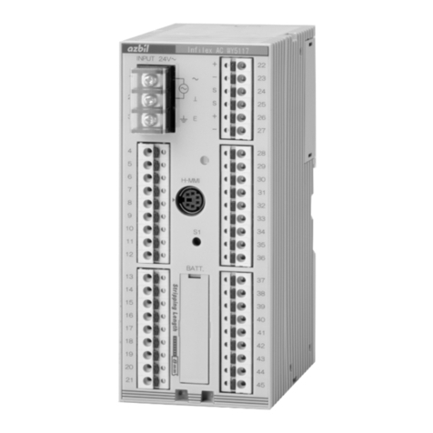
Azbil MY8045A User manual
Other Azbil Controllers manuals
Azbil
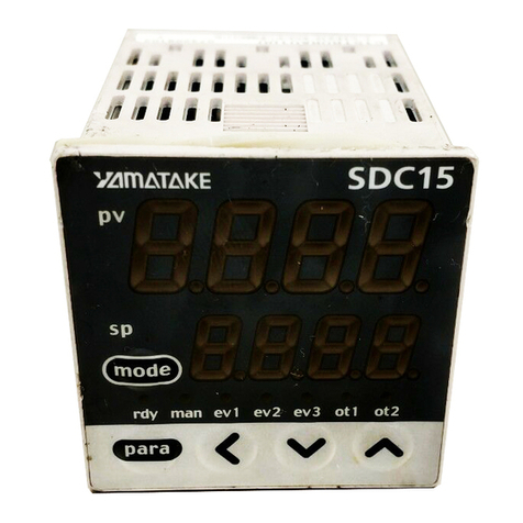
Azbil C15 User manual
Azbil
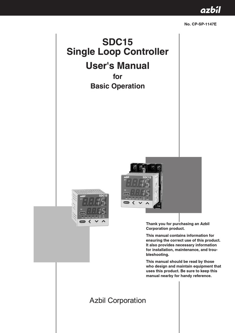
Azbil SDC15 User manual
Azbil
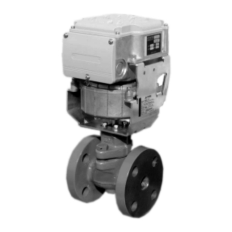
Azbil AB-7352-U User manual
Azbil
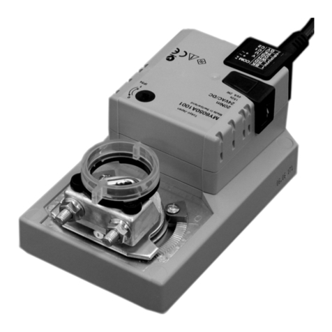
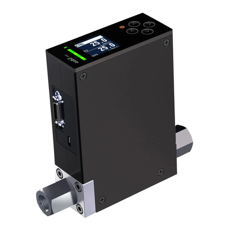
Azbil MY6050A1001 User manual
Azbil
Azbil F4Q User manual
Azbil
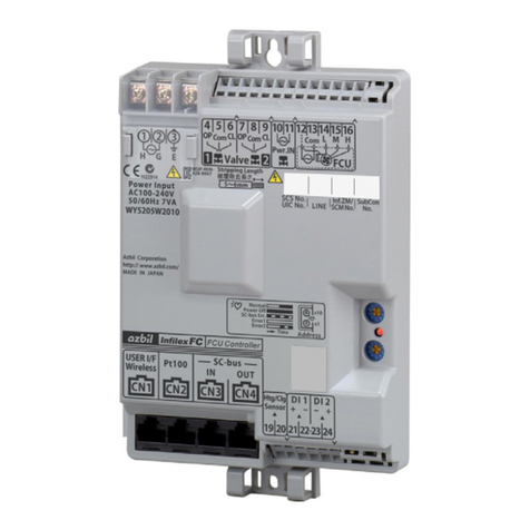
Azbil Infilex FC Series User manual
Azbil
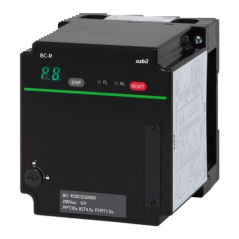
Azbil BC-R35 Series User manual

Azbil
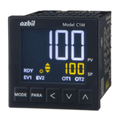
Azbil C1M User manual
Azbil
Azbil SLPC1F User manual
Azbil
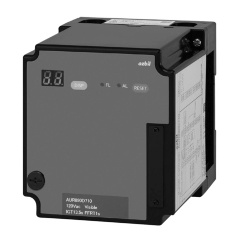
Azbil AUR890 Series User manual
Azbil
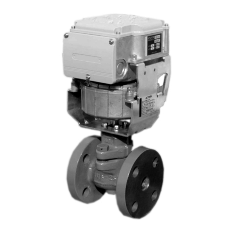
Azbil Intelligent Component Series User manual
Azbil
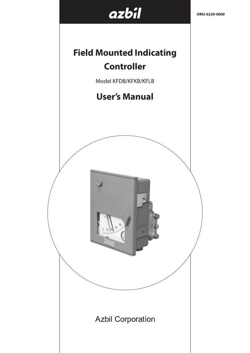
Azbil KFDB User manual
Azbil
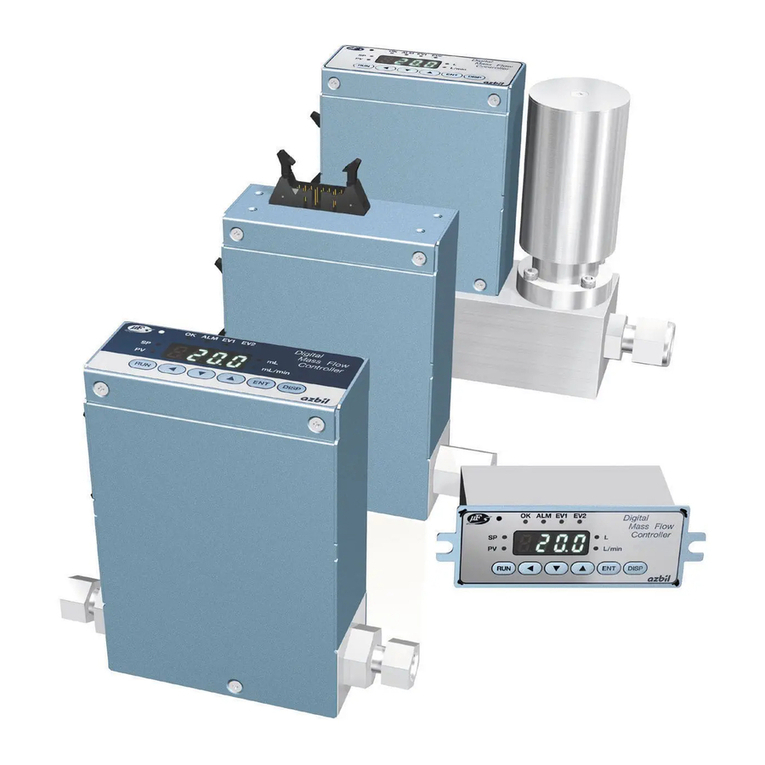
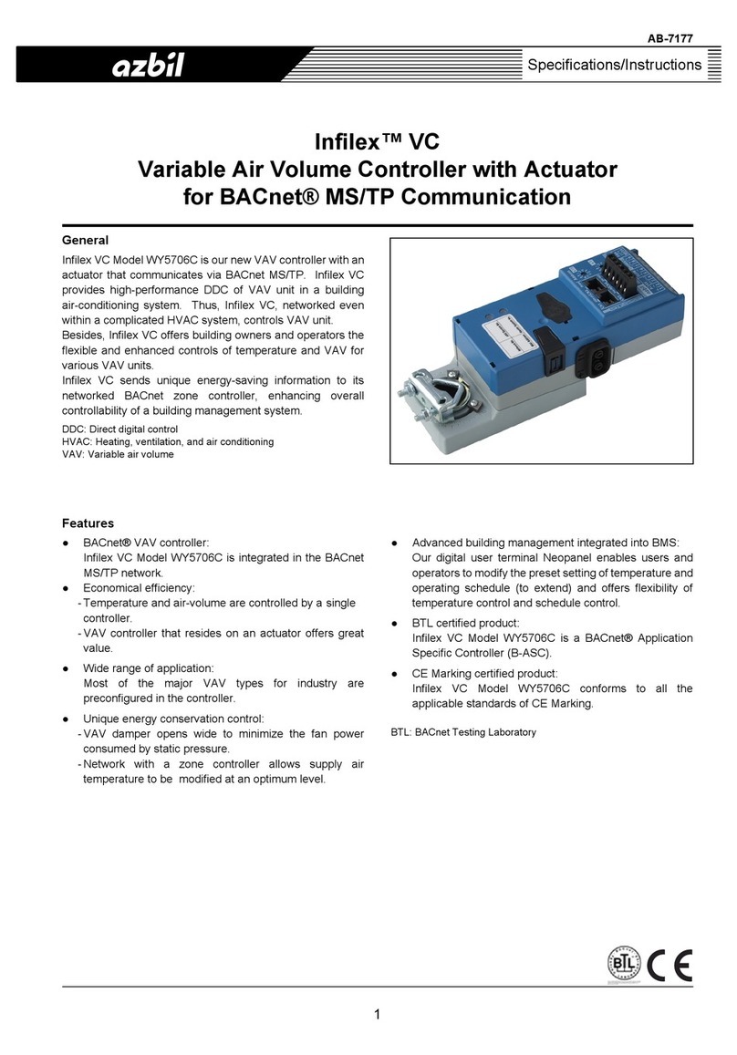
Azbil Micro Flow MQV9005 User manual
Azbil
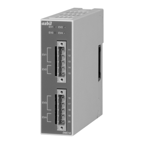
Azbil Infilex VC User manual
Azbil
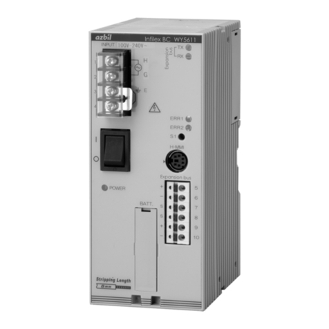
Azbil DMC10E User manual

Azbil
Azbil AUR890 Series User manual
Azbil
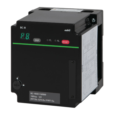
Azbil Infilex BC WY5610 User manual
Azbil
Azbil AUR890 Series User manual
Azbil
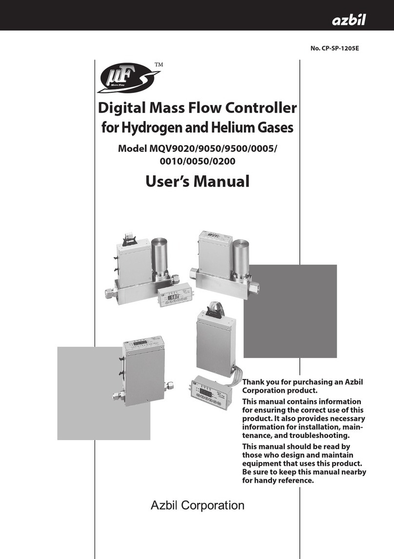
Azbil Micro Flow MQV9020 User manual
Azbil
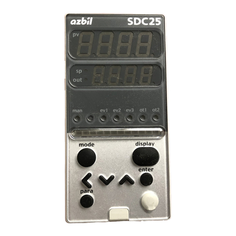
Azbil C25 User manual
Popular Controllers manuals by other brands

Digiplex
Digiplex DGP-848 Programming guide

YASKAWA
YASKAWA SGM series user manual

Sinope
Sinope Calypso RM3500ZB installation guide

Isimet
Isimet DLA Series Style 2 Installation, Operations, Start-up and Maintenance Instructions

LSIS
LSIS sv-ip5a user manual

Airflow
Airflow Uno hab Installation and operating instructions
