Connecting EME 20
Connecting to inverter
Connect the cables to the converter according to the
diagram below.
NOTE
The front cover on the inverter must not be
opened. Connection can be performed via the
intended cover under the inverter, as illus-
trated. Use the enclosed terminal block.
Connection to NIBE product
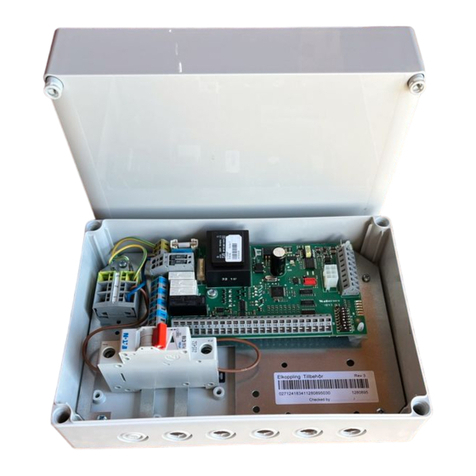
On SMO 20, the cable with pre-installed connectors must
be connected to socket X8 on the display unit and on
the terminal block AA23:1-4 on the EME 20 board.
Terminal block AA23:1-4 on the EME 20 board is connec-
ted to terminal block X4:9-12 on the input board (AA3)
in the heat pump/indoor module/control module.
Terminal block AA23:9-10 on the EME 20 board is con-
nected to terminal block 1-2 on the inverter.
External connection must be 0,5 mm² up to 50 m, e.g.
EKKX, LiYY or similar.
SMO 20
LEK
L N 1 1 0 2 3 4PE
21 20 19 18 17 16 15 14 13 12 11 10 9 8 7 6 5 4 3 2 1
11
10
982 3 4 5 6 71
21
B
GND
12V
A
X8
Inverter
SMO 20
EME 20
AA23
Green = GDN
White = A
Brown = B
Yellow = 12V
F1245/F1255 F370/470/730/750
VVM 225/310/320/325/500 SMO 40
12
1110987
11
10
98
23 4 5 6 7
1
2
1
AA3:X4
Inverter
F1245/F1255
F370/470/730/750
VVM 225/310/320/325/500
SMO 40
EME 20
AA23
F1145/F1155
EME 20 | GB10


