-2-
NDEX
1.
GENERAL INFORMATIONS ....................................................................................................................................3
1.1.
MANUFACTURER / ASSISTANCE ............................................................................................. 3
1.2.
CERTIFICATION ................................................................................................................ 3
1.3.
PURPOSE OF THE MANUAL AND ITS CONTENTS ........................................................................... 3
1.4
CARE AND STORAGE OF THE MANUAL ...................................................................................... 3
1.5.
IMPORTANT SYMBOLS TO REMEMBER ....................................................................................... 3
2.
CHARACTERISTICS OF THE DEVICE....................................................................................................................4
2.1.
RECOMMENDED USE ........................................................................................................... 4
2.2.
SCHEMATIC REPRESENTATION ............................................................................................... 4
2.3
COMPONENTS .................................................................................................................. 5
2.4
DESCRIPTION .................................................................................................................. 5
2.5
TECHNICAL SPECIFICATIONS ................................................................................................. 6
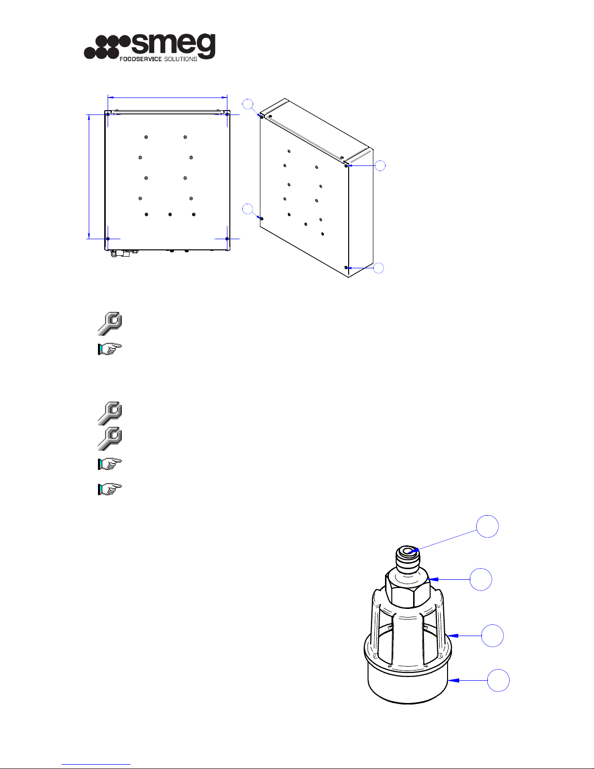
2.5
GENERAL DIMENSIONS ........................................................................................................ 7
2.6
INTERNAL LAYOUT ............................................................................................................ 7
3.
INSTALLATION ........................................................................................................................................................8
3.1
DISHWASHER REAR SIDE INSTALLATION ....................................................................................
3.2
DRAIN FITTING EN1717 .......................................................................................................
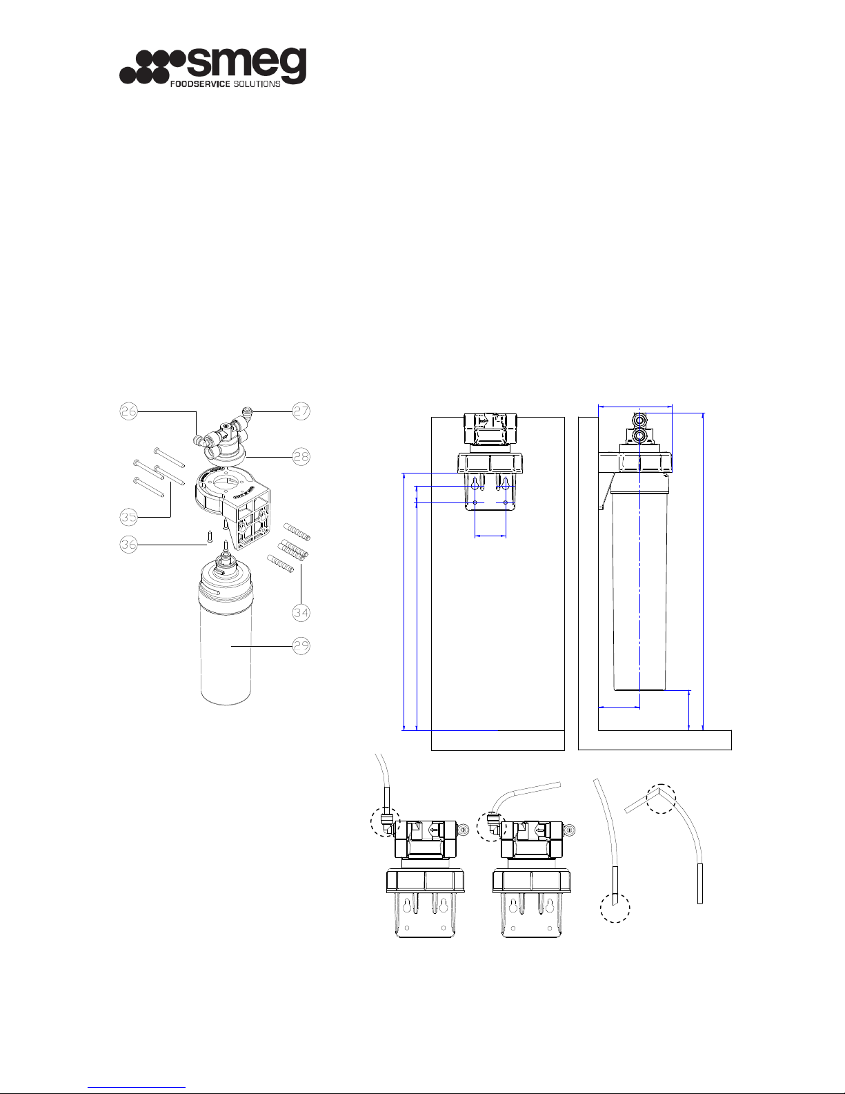
3.3
EXTERNAL PREFILTER INSTALLATION ...................................................................................... 10
3.4
DRAIN CAPILLARY REPLACEMENT .......................................................................................... 11
4.
FUNCTIONING........................................................................................................................................................12
4.1
FIRST START-UP .............................................................................................................. 12
4.2
NORMAL USE .................................................................................................................. 12
4.3
LOW PRESSURE ALARM ...................................................................................................... 12
4.4
LEACKAGE ALARM ............................................................................................................ 12
4.5
INACTIVITY .................................................................................................................... 12
5.
ENDUSER ORDINARY MAINTENANCE................................................................................................................13
5.1
FILTER REPLACEMENT ....................................................................................................... 13
6.
PROFESSIONAL EXTRAORDINARY MAINTENANCE.........................................................................................14
6.1.
REQUIRED TRAINING FOR MAINTENANCE PERSONNEL ................................................................... 14
6.2.
RESPONSIBILITIES OF MAINTENANCE PERSONNEL ........................................................................ 14
6.3
POWER CORD / POWER PLUG REPLACEMENT ............................................................................ 14
6.4
CHECK/REPLACEMENT OF OSMOTIC MEMBRANES ........................................................................ 15
6.5
PUMP REPLACEMENT ........................................................................................................ 16
6.6
CLEANING SOLENOID VALVE FILTER / SOLENOID VALVE REPLACEMENT .............................................. 17
6.7
MACHINE SANITATION ....................................................................................................... 18
6.8
FUSE REPLACEMENT / ELECTRONIC BOARD REPLACEMENT ............................................................. 1
6.
VERIFICATION OF THE PRESSURE SETTINGS .............................................................................. 20
7
TROUBLESHOOTING ............................................................................................................................................21
ATTACHMENT I – CE LABEL .........................................................................................................................................24
ATTACHMENT II – MAINTENANCE LOG.......................................................................................................................24