Smeg WO-04 Instruction manual

- 1 -
WO-04
Reverse osmosis equipment for dish/glass washmachines.
MANUAL
use and maintenance
SERIAL N°: __________________
CODE: __________________
Note: _____________________________________________

- 2 -
INDEX
1GENERAL INFORMATIONS ....................................................................................................................................3
1.1MANUFACTURER / ASSISTANCE ............................................................................................... 3
1.2CERTIFICATION .................................................................................................................. 3
1.3AIM AND CONTENTS............................................................................................................. 3
1.4CONSERVATION.................................................................................................................. 3
1.5SYMBOLS USED................................................................................................................... 3
2EQUIPMENT FEATURES.........................................................................................................................................4
2.1USE............................................................................................................................... 4
2.2PARTS THAT MAKE UP THE MACHINE......................................................................................... 4
2.3COMPONENTS.................................................................................................................... 5
2.4DESCRIPTION..................................................................................................................... 5
2.5TECHNICAL SPECIFICATIONS................................................................................................... 7
3INSTALLATION ........................................................................................................................................................8
4FUNCTIONING........................................................................................................................................................10
4.1FIRST START UP ................................................................................................................10
4.2NORMAL USE ....................................................................................................................10
4.3INACTIVITY ......................................................................................................................10
4.4ELECTRONIC BOARD OPERATING.............................................................................................10
5ROUTINE MAINTENANCE.....................................................................................................................................13
5.1MAINTENANCE PERSONNEL QUALIFICATIONS ..............................................................................13
5.2MAINTENANCE PERSONNEL TASKS ...........................................................................................13
5.3REPLACING FILTER CARTRIDGE ..............................................................................................14
5.4PRELOAD EXPANSION TANK...................................................................................................14
5.5VERIFICATION OF THE SETTING..............................................................................................15
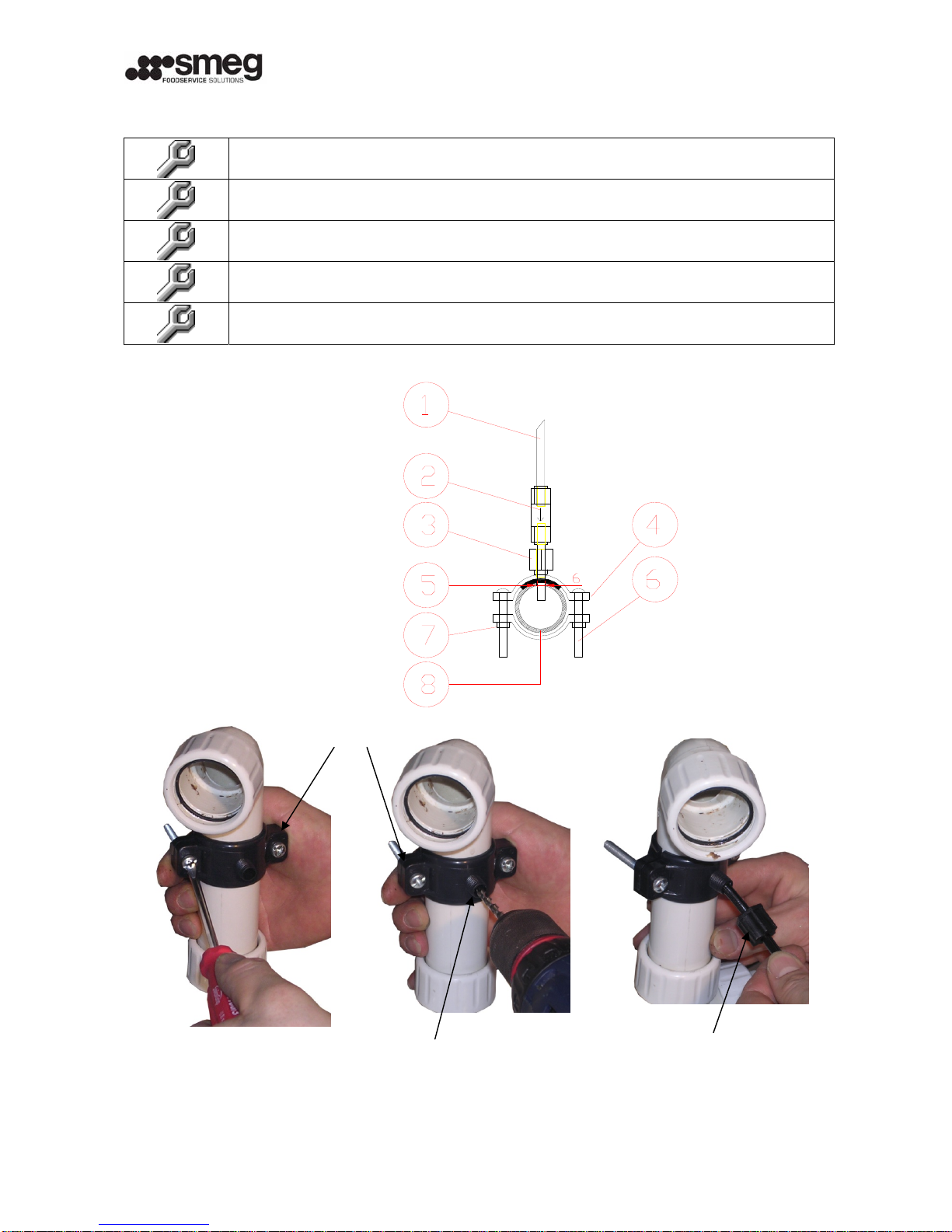
5.6CLEANING CONDUCTIVITY PROBE CONNECTORS ..........................................................................15
5.7CLEANING SOLENOID VALVES FILTER........................................................................................16
5.8MACHINE SANITATION .........................................................................................................16
6EXTRAORDINARY MAINTENANCE......................................................................................................................17
6.1ELECTRONIC BOARD WHIT DISPLAY REPLACEMENT .......................................................................17
6.2PROTECTION FUSE REPLACEMENT ...........................................................................................17
6.3PUMP REPLACEMENT ..........................................................................................................18
6.4CHECK/REPLACEMENT OF OSMOTIC MEMBRANES .........................................................................19
7TROUBLE-SHOOTING...........................................................................................................................................20

- 3 -
1 GENERAL INFORMATIONS
1.1 MANUFACTURER / ASSISTANCE
MANUFACTURE
R
ASSISTANCE
SMEG S.p.A
Via L. da Vinci, 4
42016 Guastalla (RE)
Personal Data of the Retail Seller
1.2 CERTIFICATION
WO-04 was manufactured in compliance with the following EU Directives:
Machines 2006 / 42 / CE
Low Voltage 2006 / 95 / CE
Electromagnetic Compliance 2004 / 108 / CE
1.3 AIM AND CONTENTS
The purpose of this manual is to provide the user with all the necessary information so that, apart from
correct machine use, he or she is able to run it in the most autonomous and safest way. It also includes
information on operating the machine and routine maintenance.
ATTENTION
This manual is for both users and technicians in charge of machine maintenance.
Before carrying out any operation on the machine, both the users and installation
personnel as well as qualified technicians must carefully read the instructions in this
manual.
Users can only carry out the operations indicated in this manual and must not perform
any operations reserved for maintenance personnel or qualified technicians.
ATTENTION
All maintenance operations must be performed by qualified personnel.
1.4 CONSERVATION
The instruction manual is an integral part of the machine, therefore it must be kept within reach, inside a
proper container and, above all, safe from liquids and any other substance that could make it illegible.
1.5 SYMBOLS USED GENERAL DIRECTIONS
Indicates a warning or notes on key functions or useful information. Pay the utmost
attention to texts indicated by this symbol.
Indicates a manual adjustment that can also foresee the use of portable equipment or
utensils.
Requires finding a measurement value, checking a signal, carrying out a visual control,
etc. DANGER INDICATIONS
Generic danger, with risk to the user
Danger of lectrical kind.
PROHIBITION INDICATIONS
Prohibited.

- 4 -
2 EQUIPMENT FEATURES
2.1 USE
WO-04 is an equipment designed for dish/glass wash machine water treatment. It is able to modify
organoleptic and chemical characteristics of potable water, reducing saline content.
The machine can preserve water from possible problems that can occur below the aqueducts, such as
infiltrations due to work on the network or breakage, and also from the consequences of keeping water in
decantation basins.
WO-04 is used to supply treated water to dishwasher and glasswesher machines, with frontal load.
The internal pressure tank can supply up to 5lt of treated water with an instant maximum capacity of
15lt/min, at a pressure of 2.5bar.
The treated water capacity is 1.5lt/min; water is stored in the pressure tank to supply high quantity of
water during the rinsing phase of the dish/glass washmachine cycle.
ATTENTION
The water consuption of the dish/glass washmachine installed after the WO-04 must
respect the maximum performance of the system.
All components of the dish/glass washmachine in contact with water must be compatible
with osmosi trated water.
It is forbidden to use brass; all tanks and pipes in stell AISI 304 must be without weldings.
It is racommended to use only plastic parts and stell AISI 316.
The company SMEG. is not responsible of any demage or injury to things or people if
these instructions are not respected.
ATTENTION
WO-04 is not a water purifier.
Using WO-04 to condition water that is not drinkable is ABSOLUTELY PROHIBITED.
2.2 PARTS THAT MAKE UP THE MACHINE
N° DESCRIPTION SCHEMATIC REPRESENTATION
1 SOLENOID VALVE
2 MINIMUM PRESSURE
SWITCH
3 INTERNAL
PREFILTER
4 PUMP
5 MEMBRANES
6 VALVE MIX
7 CALIBRATED PIPE
8 CHECK VALVE
9 MAXIMUM PRESSURE
SWITCH
10 EXPANSION TAN
K
11 CONDUCTIVITY
PROBE
Inlet ¾”
Drain
Outlet ¾”G
Auxiliary outlet

- 5 -
2.3 COMPONENTS
2.3.1 Internal prefilters
The device is equipped with a cartridge PROFINE carbon block.
2.3.2 Membrane
The membranes are the core of the machine; two membranes TW3012 300gpd are installed.
2.3.3 Pressure Tank
The machine has inside a 24lt pressure Tank with replacable membrane to store trated water.
2.4 DESCRIPTION
The machine has on the rear side no.4 hydraulic connections, for inlet water, permeated water, drain and
auxiliary permeate outlet.
On the rear side, there is also the electric socket whit fuse.
On the front side of the machine, there is the electronic board with display, the ¼ turn rapid filter and
the mix valve.
N° DESCRIPTION GENERAL SCHEMATIC REPRESENTATION
1 POWER SOCKET
2 PERMEATED
OUTLET
3 SOLENOID VALVE
WATE INLET
4 AUXILIARY
OUTLET
5 DRAIN
6 FILTER
7 ELECTRONIC
BOARD
8 MIX VALVE

- 6 -
From the inlet valve, the water flows to the inlet solenoid valve, on the rear side of the machine, and
then through the prefilter.
After prefiltering, the water is pumped at high pressure to the osmosis vessel with membranes.
The sediment filtration removes suspended solids from water that may damage pump and membranes.
The activated carbon filters facilitate the elimination of the unpleasant chlorine taste, without
compromising the desirable mineral properties of the water. These activated carbon filters can also
absorb potential trace organic micro pollutants, various chemicals organic and inorganic (i.e. chlorine
composites), chlorine residue used to disinfect water, haloforms, pesticides, surface-active agents.
The reverse osmosis phase is the last and most important process that occurs inside the membrane itself.
The water permeates the layer flowing into the collection tubes, and then it is directed to the main tube
of the membrane, wrapped in various layers. The permeate yield comes from the main tube of the
membrane and is sent directly to the permeate outlet.
While the membrane allows the water to filter through, it traps the unwanted concentrated impurities.
The drainage flow is also used to clean the membrane and is directly connected to the drainage system by
plastic brackets.
The mix valve allows the user to choose the hardness or the saltiness of the water produced. The mixer
should be calibrated during the installation phase.
WO-04 permits the treated water to retain about 10 to 15% of the original saline properties.
The machine has a conductivity probe to check water quality on the display.
For the start/stop signal, the machine has a high pressure switch on the permeate line.
For pump safety, the machine has an adjustable minimum pressure switch.
The machine has an auxiliar bypass solenoid valve to supply raw water if water consumption is higher than
the maximum performance of the machine.
ATTENTION
The percentage of dissolved salts and other rejected elements is influenced by the water
quality, temperature, pressure, and total dissolved salts and differs according to the type
of salts or elements.
The treatment of particularly turbid water or water with many impurities can clog the
prefilters and/or membranes, causing a loss in water flow rate.
Reflux water, salt water or water in chemical, physical and bacteriological conditions
that cannot be treated by Reverse Osmosis (industrial reflux or chemical processing)
cannot be treated.

- 7 -
2.5 TECHNICAL SPECIFICATIONS
WO-04
STANDARD
TECHNICAL SPECIFICATIONS EASY:WASH
Height x Width x Depth (mm) 300x462x688
Weight (kg) 30
Approved Decibel Level under normal operating conditions
(dB (A)) <70
R/O Membrane (n° 2) 3012 300GPD
Filter with active carbon cartridge PROFINE medium.
WATER SUPPLY SPECIFICATIONS
Water type Drinkable
Minimum temperature (°C)
5
Maximum temperature (°C) 30
Minimum inlet capacity (l/h) 400
Maximum inlet pressure (bar) 3
Minimum inlet pressure (bar) 1,5
POWER SUPPLY SPECIFICATIONS
Power supply type MONOPHASE + GROUND
Voltage (V) 230
Frequency (Hz) 50
Absorbed current (A) 2.5
A
Power (W) 250
W
Fuse type electronic board
F5
A
Fuse type elettrica connecto
r
F4
A
PERMEATE WATER SPECIFICATIONS
Maximum capacity at 15° C (l/h) c.a 120
Flow with pressure at 3 bar of 15°C (l/h) c.a 80
Recovery (%) c.a 50
OPERATION UNDER NO
R
MAL WORKING CONDITIONS
Filter with active carbon (l) 22.000
R/O Membrane UPON CLOGGING
ATTENTION
Any use of this device, which has not been stipulated in this manual, will constitute
IMPROPER USE, thereby rendering the guarantee null and void. The manufacture WILL
NOT be liable for any damages caused by the IMPROPER USE of this device, due to
negligence, failure to follow the manual, or permitting unauthorized maintenance
personnel to tamper with machine.

- 8 -
3 INSTALLATION
WO-04 installation must be performed in a cool, dry and well ventilated place.
ATTENTION
WO-04 must be installed by qualified
personnel and in compliance with regulations,
there must be a tap above (to exclude the equipment from the water system in the case
of maintenance interventions), a check valve, water supply pipes above and below the
equipment and an electrical outlet.
Avoid subjecting the machine to excessive temperature changes that could cause
condensate to form inside, which can damage the electronic part.
Make sure the air vents are never blocked in order to not compromise motor cooling.
Instructions and representation to follow are to be considered for typical installations,
the specific components may vary depending on the accessories that accompany the car
and taps derivation and delivery chosen.
CONTROLS TO BE CARRIED OUT BEFORE INSTALLATION
Mains grounding present and efficient
Main compatible with the electrical specifications indicated on the plate on the back of the
machine
Diameter of feed circuit electrical wires greater than 1 mm
Stability of network tension (rushes lower than 10%)
TYPICAL INSTALLATION DIAGRAM
DESCRIPTION.
1 POWER SOCKET
2 PERMEATED OUTLET
3 SOLENOID VALVE WATE INLET
4 AUXILIARY
OUTLET
5 DRAIN
6 FILTER
7 ELECTRONIC BOARD

- 9 -
3.1 INSTALLING THE DRAIN CLAMP
Install the drain clamp on the drain siphon diam. 40mm of the sink.
Make sure the washer correctly rests on the pipe and the bolts are tightened.
Remove the screw nut from the drainpipe.
Using a drill with 4-mm tip, make a hole in the drain siphon pipe in correspondence
with the nut that has just been removed.
Insert the drainpipe in the nut for about 2 cm and screw the nut on the clamp.
Fasten the screw nut and install the check valve with the arrow pointing towards the
clasp, as near as possible to the drain.
1. Drain pipe 6mm
2. Check valve 6mm
3. Drain pipe screw nut
4. Drain clasp
5. Washer
6. Bolt
7. Bolt screw nut
8. Sink drain siphon pipe
Drain clamp
Bolt screw nut
Hole diam. 4mm

- 10 -
4 FUNCTIONING
4.1 FIRST START UP
ATTENTION
The first start up of the system must be carried out by the installer who will make sure
the machine runs properly.
Insert the feed plug in a 230V 50Hz outlet equipped with efficient grounding. Now the
system is able to work. It advisable to run the run for at least a half an hour before
drinking it, in order to allow the system to eliminate the substances used to conserve the
reverse osmosis membrane.
Make sure there are no leaks in the circuit and fasten the antiflooding probe on the
bottom of the machine.
Close the cover with the screws position the machine in its final destination and push the
brakes of the whells.
Operate sanitation of equipment as described in section 5.8.
The WO-04 membranes are provided saturated in a maintenance solution. Before taking water, let it run
for at least 15-30 minutes.
4.2 NORMAL USE
In order to normally use WO-04 the machine must always be kept on.
The machine starts automatically at every rising cycle of the dish/wash machine. Every six hours the
machine automatically opens the inlet solenoid valve, in this way the membranes are washed for 2
minutes.To adjust the salinity of the water, acting on the valve for mixing later.
If high water consumption occurs, the by-pass solenoid valve opens and raw water flows to the outlet.
ATTENTION
Absolutely avoid letting the membranes dry out; this could irreparably compromise its
functioning.
4.3 INACTIVITY
ATTENTION
It is advisable, each time the machine is inactive for a period over one week, to let the
water run for at least 10 minutes before using it.
It is advisable to sanitize the system every six months during routine maintenance
procedures.
Contact assistance in order to carry out this operation, which must be performed by
specialized personnel/installation technicians.
4.4 ELECTRONIC BOARD OPERATING
4.4.1 Normal functioning
When the card is in normal functioning mode, the name of the reseller is
displayed.
When the faucet is opened, the machine starts to produce permeate water;
pushing the key ENTER , the conductivity is displayed.
SMEG
uS/cm
0050

- 11 -
When the faucet will be closed, the board returns in stand-by mode.
Main water pressure failure
When faucet is opened, if low pressure failure occurs, the display shows “Alarm
P. min” and the board makes a beep.
To restart the machine, turn OFF and ON with the key .
Leakage
If water leakage alarm occurs, the machine stops and makes a continuous beep
displaying “Alarm Leakage”.
To restart the machine, turn OFF and ON with the key .
4.4.2 Display pages
When the card is in stand-by mode, the name of the installer is displayed.
Pressing the key displays the version of software installed in the card.
To scroll the next pages press the key ; the first page displayed enables
carryng out the manual flow of the membrane; in order to carry out the
operation, press the key; the card displays “Flow in progress”.
Pressing the key again moves to the display of the hours-minutes of
remaining functioning before the filter change; from this page, pressing the key
displays the residual autonomy.
Pressing the key again moves to the display of the hours-minutes of
running since the last reset; from this page, pressing the key displays the
total liters consumed.
4.4.3 Programming pages
Alarm
P. min
WO-04
Alarm
Leakage
Mikrotec
Ver 1.02
Manual
Flush.
Flushing
T Total
0000:00
L Total
0000000
T remain
0000:00
L remain
0000000

- 12 -
In order to have access to the programming pages, unplug the machine and press
the key while connecting the feed plug.
Subsequently the card will require pressing the key to confirm access to
the programming.
Scroll the programming pages with the and keys.
Each time a value is modified, press the key to confirm the change and
save the datum; “Loaded value” appears on the display and it returns to the
programming menu.
The first page enables the hour counter reset by pressing the key.
The card displays “press E Reset T”; pressing the key again confirms the
zeroing of the counter; the card will therefore display “Data saved”
Move to the next page with the key; access the selection of the tap type
with the key. Select the type of tap (manual or electric) with the
and keys and confirm with the key. The card therefore indicates
“Data saved”
Move to the next page with the key; access the selection of the writing in
stand-by with the key. Select the saved names with the and
keys and confirm with the key. The card therefore indicates “Data saved”
Move to the next page with the key; access the selection of the
functioning mode with the key. Select functioning by time or without time
limit with the and keys and confirm with the key. The card
therefore indicates “Data saved”
In equipment for hosehold use the time limit functioning is recommended.
Settings
Press E
Data
saved
Filter
Reset
Press E
to reset
Faucet
Setting
Manual
Faucet
Customer
Setting
WO-04
Function
mode
Time
limit

- 13 -
Move to the next page with the key; access the modification of the
liters/hour conversion parameter with the key. Modify the value with the
and keys and confirm with the key. The card therefore
indicates “Data saved”
Move to the next page with the key; modify the “filter hours” parameter
with the key. Modify the value with the and keys and
confirm with the key. The card therefore indicates “Data saved”
Move to the next page with the key ; modify the language parameter with
the key . Set the language with the keys and and confirm
with the key . The card therefore indicateds “Data saved”.
5 ROUTINE MAINTENANCE
5.1 MAINTENANCE PERSONNEL QUALIFICATIONS
Personnel in charge of Maintenance must have the requisites indicated in the following and be familiar
with this manual and all information concerning safety:
Sufficient level of general and technical knowledge in order to understand the contents of this
manual.
Knowledge of the main hygienic, accident-prevention and technological regulations.
Complete knowledge of the machine as well as electrical and hydraulic problems that can arise
where the machine is installed.
5.2 MAINTENANCE PERSONNEL TASKS
The routine maintenance program described in this paragraph must be carried out according to the
schedule indicated in order to keep the machine running efficiently and to guarantee the quality of the
water treatment.
ATTENTION
The operations indicated in the following must be carried out by qualified personnel
according to the instructions in this manual and only using original spare parts.
Maintenance performed must be documented and signed by the technician in charge
in the proper space on the maintenance register in the ATTACHMENT.
It is advisable to carry out routine maintenance at least once every 6 months, even if
the filters have not run out.
Time
setting
Funz
h 0070
K convers
setting
K Convrs
lt/h 180
Set
language
Set
English

- 14 -
ITEM TO CHEC
K
CONTROL
FREQUENC
Y
Machine
Preload expansion tank 6 MONTHS
o
10000 liters
(*)
22.000 liters
Visual control of the integrity and state of
conservation
General cleaning
Check running
Filters with active carbon Replacement
(*)Particular water conditions can require more frequent maintenance.
ATTENTION
Use only original parts SMEG.
ATTENTION
The internal WO-04 electrical apparatus is fed by 230-VOLT electrical current.
Before opening the machine, remove covers and/or panels and/or protection grids and
make sure the switch is off and the machine is unplugged.
ATTENTION
When cleaning the machine do not use corrosive products, acids, abrasive or steel
brushes.
Do not directly wash the machine with high-pressure jets of water.
5.3 REPLACING FILTER CARTRIDGE
The repleace the prefilter follow these steps:
Remove the power plug.
Remove the filter cartridge, turning it left ¼.
Install new cartridge in the machine; take caref about the filter o-rings.
Reset the electronic board (if used with time limit funciont) (see § 4.4.3).
Sterilize the system (see § 5.8).
5.4 PRELOAD EXPANSION TANK
To check the preload of the pressure tank,
follow these steps:
Remove the power plug.
Empty the expansion tank delivering water to the permeate auxiliary outlet.
Remove the side panels and identify the connection of the preload in the tank.
With a compressor and a pneumatic gun, bring the preload pressure at 2.5bar
Install the panels and connect the power plug.

- 15 -
5.5 VERIFICATION OF THE SETTING
For proper operation of the machine, check periodically the calibrations.
All the calibrations must be performed by qualified personnel.
5.5.1 Setting pressure switch
vit e r egol azione
pr essost at o
5.5.2 Check operating pressure
5.5.3 Calibrating conductivity probe
5.6 CLEANING CONDUCTIVITY PROBE CONNECTORS
Install a pressure gauge (0-6 bar or similar) between
the permeate outlet and the faucet.
Screw two turns the calibration nut of the pressure
switch.
Open the knob of the tap, after which it slowly close
the tap until the pressure gauge reaches about 3.5 bar.
Slowly unscrew the calibration nut of pressure
switch
until the operation of the machine becomes
discontinuous.
Apply the glue sealant to calibration nut.
Install a T fitting and a pressure gauge 0-10 bar (or similar) on the pump outlet line.
The operating pressure must be between 6 and 7 bar.
Open the electronic board box.
Start the machine and deliver water.
After 2 minutes, take a sample and measuring the
conductivity with a reference instrument properly
calibrated.
Turn the conductivity calibration potentiometer until
the displayed value matches the value measured by
the instrument.
Disconnect the connectors of the conductivity probe.
Clean the male and female connectors from possible
oxidation.
Tighten the connector with pliers and reassembly.

- 16 -
5.7 CLEANING SOLENOID VALVES FILTER
5.8 MACHINE SANITATION
Perform the sanitation of the machine at each filter replacement, and at intervals not
exceeding 6 months.
Perform sanitation also after long not-use periods of the machine.
All sanitation operations must be performed by qualified personnel.
Be careful in the use and dosage of chemicals.
Use protective clothing to the skin, hands and eyes as shown in the safety data sheet
of chemicals used.
Close the mixing valve and fill a tank with 10 liters of permeate water.
Add hydrogen peroxide to achieve a concentration of 0.2% by weight.
Put 650ml of hydrogen peroxide at 10 volumes per 10 liters of permeated water.
Put 250ml of hydrogen peroxide at 24 volumes per 10 liters of permeated water.
Put 180ml of hydrogen peroxide at 36 volumes per 10 liters of permeated water.
Put 50ml of hydrogen peroxide at 130 volumes per 10 liters of permeated water.
Connect the water pipes of entry, drain and permeated by the machine, at the tank;
make a bridge on the low pressure switch connectors.
Open a bit the mix valve and turn on the machine and let the solution recirculated for at
least 10 minutes.
Wait 10 minutes that the solution acts on the machine.
Reconnect the drain and permeated pipes.
Connect the water pipes of entry, drain and permeated by the machine, at the tank.
Turn on the machine until the sanitation solution is empty; then turn off the machine.
Reconnect the inlet water pipe and open the water valve.
Replace the filter and reconnect the cables of the minimum pressure switch.
Turn on the machine and suplly water for at least 10 minutes until the sanification
solution resids are totally drained.
Close the inlet water valve.
Open the faucet to remove the pressure in the feed
pipe.
Turn off the machine and remove the ¾” fitting from
the solenoid valve.
Using pliers, gently pull the solenoid valve filter.
Clean the filter with tap water and/or compressed air.

- 17 -
6 EXTRAORDINARY MAINTENANCE
ATTENTION
The internal WO-04 electrical apparatus is fed by 230-VOLT electrical current.
Before opening the machine, remove covers and/or panels and/or protection grids and
make sure the switch is off and the machine is unplugged.
6.1 ELECTRONIC BOARD WHIT DISPLAY REPLACEMENT
Remove the cover of the machine, accessing the tray card.
Unscrew the screws fastening the electronic board box.
Remove the electronic board box, disconnect the power connector.
Mount the new electronic board with reverse procedure.
6.2 PROTECTION FUSE REPLACEMENT
The machine is equipped with two fuses, one on the electronic board and one on the power socket.
6.2.1 Protection fuse replacement on power socket
Remove the fuse compartment under the attack of the power cord.
Replace the burned fuse with a similar. (Attachment V)
Mount the power cord with reverse procedure.
DESCRIPTION.
1 M4 SCREW
2 ELECTRONIC BOARD

- 18 -
6.2.2 Protection fuse replacement on electronic board
Remove the top cover of the machine, accessing the tray card.
Remove the support and the cover of the electronic board.
Replace the burned fuse with a similar. (Annex V)
Mount the electronic board with reverse procedure.
6.3 PUMP REPLACEMENT
Remove the top and right panels of the machine.
Disconnect the piping from the pump.
Unscrew the screw of the clamp connecting and disassemble the pump.
Install the new pump with fittings previously removed.
Mount the new pump with reverse procedure.

- 19 -
6.4 CHECK/REPLACEMENT OF OSMOTIC MEMBRANES
A decay of performance rating of 10% per year is considered normal wear for osmotic
membranes. Special conditions of entry and/or high consumption may accelerate the
clogging of the membranes.
Close the mixing valve completely.
Supply water and verify scope permeated and conductivity with a reference tool.
If the capacity is reduced more than 50% of the initial conditions and/or the conductivity
is greater than 80 μS/cm, replace the osmotic membrane as follows.
Disconnect the tubes from the fittings of the vessel containing the membrane.
Dismantle the vessel from the machine and unscrew the caps.
Dismantle the membranes clogged and replace with new membranes of the same type.
Clean the vessel on the inside by removing all traces of dirt and scale.
The new membrane must be removed immediately prior to their installation and
handling, using protective gloves sterile.
Before installing the membrane in the vessel, lubricate the o-ring and the upper seal.
Install the vessel with reverse procedure.
Supply water for at least 15 minutes, then check permeated flow and quality.
4
5
1
2
3
7
86
DESCRIZIONE.
1 INLET
2 CAP VESSEL
3 VESSEL
4 PERMEATE
5 DRAIN
6 O RING VESSEL
7 MEMBRANE 3012
8 O RING VESSEL

- 20 -
7 TROUBLE-SHOOTING
The operations indicated should be performed only by qualified personnel, except
those marked with *.
Problem: The display is off.
Cause Solution
Electric supply failure. Check power plug is connected. *
Burned fuse. Open the board cover and check the fuse; if burned replace it.
Display cable removed. Check display cable is connected on the board socket.
Damaged display. Replace the display.
Damaged board. Replace the board.
Problem: Burned fuse and thermal protection switch.
Cause Solution
Motor in short circuit. Replace the motor and the protection fuse of the electronic board.
Incorrect wiring. Check the wiring and the fastening of the cables to the terminals.
Leakage. Check the insulation of the wiring and clamp, and check the operation
of the electronic board.
Problem: The ground protection switches.
Cause Solution
Defective motor. Replace motor.
Incorrect wiring. Check the wiring and the fastening of the cables to the terminals.
Problem: The display shows “Alarm Leakage”.
Cause Solution
Leakage Open the machine and check carefully all hydraulic circuit for
leakages.
Leakage probe in short
circuit.
Check water leakage probe position; if directly at contact with metal
parts of the machine, place in a different position.
Damaged board. Replace the board.
Problem: With the display turned on and running, after opening the faucet, the engine will
not start.
Cause Solution
Vane pump blocked. Replace the vane pump.
Burned motor. Replace the motor.
Incorrect wiring. Check the wiring and the fastening of the cables to the terminals.
Incorrect faucet setting
manual / electric.
Access the programming menu of the electronic board and check the
faucet setting.
Problem: With the board on, at operating start, the inlet solenoid valve never opens.
Cause Solution
Solenoid valve damaged. Replace the solenoid valve.
Coil burned. Replace solenoid valve coil.
Electric connection failure. Check electric connections and tight if necessary.
Table of contents
Other Smeg Water Filtration System manuals
Popular Water Filtration System manuals by other brands

Trapzilla
Trapzilla TSS-95-ECA Installation & maintenance instructions

Filtreco
Filtreco Basic combi drum 25 user manual

Ecosoft
Ecosoft AquaPoint FPV24520ECO user manual

BWT
BWT AQA drink TC200 Installation and operating instructions

Pure-Pro
Pure-Pro WF-30 user manual

Vulcan-Hart
Vulcan-Hart 85MF Specifications