3
LED Lights Explanation and Troubleshooting
Each ash indicates 3dB of gain reduction also known as gain attenuation.
For example: three ashes equals 9dB of attenuation.
Band 12, 17 700MHz Lower
Band Frequency
Bande Fréquence
Band 13 700MHz Upper
Band 5 850MHz
Band 4 1700/2100MHz
Band 2, 25 1900MHz ext
RX High Power Attenuation
Atténuation de haute puissance de RX
Oscillation Attenuation
Atténuation de l'oscillation
Orange LED Orange
Green LED Vert
Hp Att
Osc Att
4
Chaque ash indique 3dB de réduction de gain aussi connu comme atténuation
de gain. Par exemple: trois clignotements égal 9dB d'atténuation.
La DEL verte indique l'état de boucle d'oscillation . Lorsqu'il clignote, cela signie
une réduction du gain. Pour améliorer vous devez étendre la distance entre les
antennes de l'intérieur et l'extérieur. Si vous les étalez assez loin , la DEL verte
deviendra ALLUMÉ SOLIDE.
The LED lights on the booster face plate indicate the operating gain state
of the booster.
The Green and Orange lights indicate the gain status in each operating band
When Both Green and Orange LED's are“SOLID ON”it means that the booster
is operating normally with full gain (No Automatic Gain Reduction)
When one or both of the LEDS are ashing (Per the chart on back cover) it
indicates that the gain has been automatically reduced due to either:
A) High RX outside signal level (close to cell tower)
B) Loop Oscillation, which is due to the inside antenna (either on holder or
Patch antenna) and the outside antennas are located too close together.
Green LED indicates loop oscillation status. When ashing it means reduction of
gain. To improve you need to spread the distance between the inside and outside
antennas. If you spread them far enough away, the Green LED
will become SOLID ON.
Orange LED There are 5 Orange LED lights: 700 Mhz Lower, 700 Mhz Upper,
850 Mhz, 1700/2100 Mhz,1900 Mhz ext.
LED ON state indicates that the RX (Receive Signal) function of the band is
functioning normally.
LED OFF (Green or Orange): indicates that the band is shut down.
When ashing it means reduction of gain also known as attenuation of gain.
You cannot prevent this condition. As you drive away from the nearby cell tower
and get far enough away the ashing Orange will automatically stop ashing
which indicates that the booster is no longer attenuated. As you approach
another nearby cell tower the Orange may begin ashing again and will stop
ashing as you get farther away. This is the normal operating process.
Optional Desktop
(Additional parts required which are
not included in Booster kit.)
Application De Bureau
(Pièces supplémentaires requises, qui
ne sont pas inclus dans le kit.)
Understanding the LED Indicators
6
1
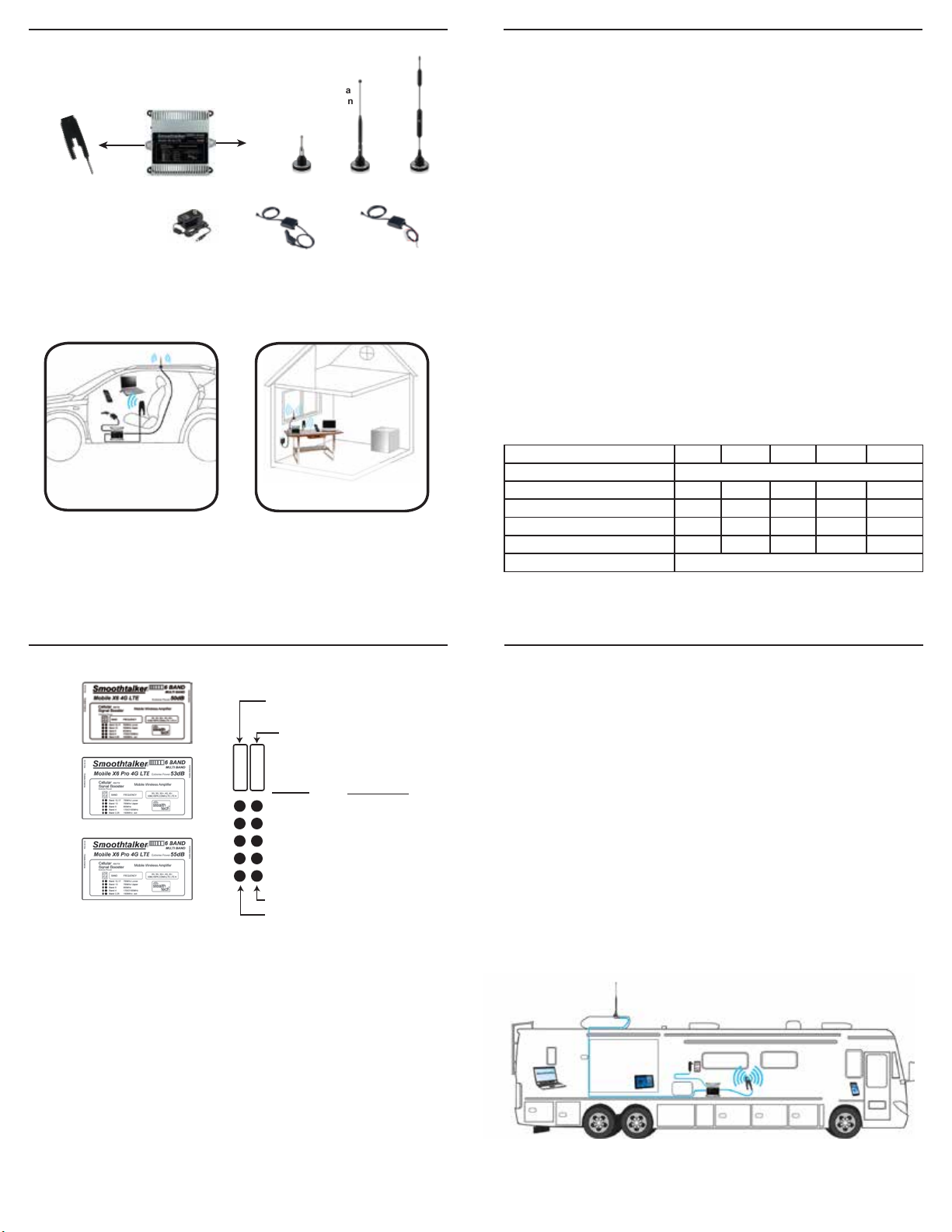
Contents-Contenu
Cellular Booster
Amplificateur
Optional outside antenna
Antenne externe en option
12 volt install type
12 volts type d’installation
12 volt socket plug type
12 volts type de fiche
120 volt AC/DC
120 VAC / DC
Optional Power Types
Types d’alimentation
en option
Inside antenna
Antenne intérieure
SRP1X SEM2MX SEM11MX SEM14MX
RADIATED POWER
PUISSANCE RAYONNÉE
OPERATIONAL BANDS -
GROUPES OPÉRATIONNELS
3 Watts EIRPX6 4G LTE X6 Pro 4G LTE
Band 2/25Band 4Band 5Band 13Band 12/17
WEIGHT- POIDS 1.2 lb / 0.530 kg
NOMINAL BANDWIDTH
LARGEUR DE BANDE NOMINALE 77.9 MHz80.8 MHz41.0 MHz30.1 MHz30.2 MHz
26.8 dBm27.9 dBm26.5 dBm25.0 dBm24.9 dBm
-3.1 dBm-2.1 dBm-2.0 dBm-1.1 dBm-3.3 dBm
RATED MEAN OUTPUT (uplink)
RENDEMENT moyen évalué (liaison montante)
RATED MEAN OUTPUT (dowlink)
RENDEMENT moyen évalué (dowlink)
NOMINAL PASSBAND GAIN
GAIN DE BANDE PASSANTE NOMINALE 52.8 dB52.8 dB53.0 dB53.3 dB53.3 dB
IMPEDANCE (input/output)
IMPÉDANCE (entrée/sortie) 50 Ohms - 53 Ohms
Qu'est-ce que les clignote DEL signient?
NOTE: Only one of the outside antennas is included in this kit (check model) All kits include necessary brackets and co-axial
cables for assembly. It is normal for the booster to be quite warm while the phone is in use state.
REMARQUE: Seule une des antennes extérieures est incluse dans ce kit (vérier le modèle) Tous les kits comprennent les supports
nécessaires et les câbles coaxiaux pour le montage. II est normal pour le booster d’être assez chaud pendant le fonctionnement
Typical Vehicle Installation Mobile X650
(All parts are included/
La trousse inclus)
Industry Canada Information to Users
This product meets the applicable Industry Canada technical specications. The Class [B] digital
apparatus meets all requirements of the Canadian Interference-Causing Equipment Regulation.
The Manufacturer’s rated output power of this equipment is for single carrier operation.
For situations when multiple carrier signals are present, the rating would have to be reduced by
3.5 dB, especially where the output signal is re-radiated and can cause interference to adjacent band
users. This power reduction is to be by means of input power or gain reduction and not by an
attenuator at the output of the device.To comply with ICAN MPE limits: Antennas MUST be
installed at least 20 cm (8 inches) from any person. Changes or modications not expressly
approved by Mobile Communications Inc., the party responsible for compliance,
could void the user’s authority to operate the equipment.
Industrie Canada Information pour les utilisateurs
Ce produit est conforme aux spécications d’Industrie Canada.
La classe [B] appareil numérique est conforme à toutes les exigences du règlement équipement
brouilleur du Canada. Classé la puissance de sortie du fabricant de cet équipement est unique
pour fonctionnement de la porteuse. Dans les situations où les signaux porteurs multiples sont
présents, la note aurait à réduire de 3,5 dB, en particulier lorsque le signal de sortie est re-rayonnée
et peut causer interférence aux utilisateurs de bande adjacente. Cette réduction de puissance est
eectuée au moyen de la puissance d’entrée ou la réduction de gain, et non par un atténuateur à la
sortie du dispositif. Pour respecter les limites de MPE ICAN: Antennes doivent être installés à au
moins 20 cm (8 po) de toute personne. Les changements ou modications non expressément
approuvés Mobile Communications Inc., la partie responsable de la conformité, pourraient annuler
l’autorité de l’utilisateur à utiliser l’équipement.
Typical RV Installation Mobile X653 (Fig. 3 )
(All parts are included/
La trousse inclus)
La DEL Orange DEL orange, Il y a 5 lumières DEL orange : 700 MHz Bas, 700 MHz
Haut, 1700/2100 MHz ext. Statut DEL allumée indique que la fonction RX
(signal reçu) de la bande fonctionne normalement. DEL État éteint indique que
la bande est arrêté.
Lorsqu'il clignote, cela signie une réduction du gain aussi connu comme
l'atténuation du gain. Vous ne pouvez pas empêcher cette condition. Comme vous
conduisez loin de la tour cellulaire à proximité et obtenir assez loin le clignotement
orange arrête automatiquement de clignoter qui indique que l'amplicateur n’est
plus atténué. Comme vous appproch une autre tour cellulaire à proximité. Orange
peut commencer à clignoter et cesse de clignoter comme vous obtenez plus loin.
Ceci est le mode de fonctionnement normal.
Fig. 1
Mobile Wireless 12 V Socket CLA plug-in Type
Sans l mobile avec prise 12 volts
type allume-cigare
Sans Fils de Bureau avec
adaptateur 120 volts
Fig. 2
Desktop Wireless with 120 volt adapter


