Snell IC-Basis 300 User manual

Owner‘s Manual
Basis 300
IC-Basis 300
Powered Subwoofer

2
SAFETY INSTRUCTIONS
Warning: To reduce the
risk of fire or electric
shock, do not expose this appliance to rain or moisture.
The lightning flash with arrowhead symbol,
within an equilateral triangle, is intended to
alert the user to the presence of uninsulated ”danger-
ous voltage“ within the product’s enclosure that may be
of sufficient magnitude to constitute a risk of electric
shock to persons.
The exclamation point within an equilateral
triangle is intended to alert you to the presence
of important operating and maintenance (servicing) in-
structions in the literature accompanying the appliance.
Read Instructions: All the safety and operating instruc-
tions should be read before the appliance is operated.
Retain Instructions: The safety and operating instruc-
tions should be retained for future reference.
Heed Warnings: All warnings on the appliance and in
the operating instructions should be adhered to.
Follow Instructions: All operation and other instruc-
tions should be followed.
Water and Moisture: The appliance should not be used
near water—for example, near a bathtub, washbowl,
kitchen sink, laundry tub, in a wet basement, or near a
swimming pool, etc.
Carts and Stands: The appliance should be used only
with a cart or stand that is recommended by the manu-
facturer.
Wall or Ceiling Mounting: The appliance should not be
mounted to a wall or ceiling.
Ventilation: The appliance should be situated so that its
location or position does not interfere with its proper
functioning. For example, the appliance should not be
situated on a bed, sofa, rug, or similar surface that may
obstruct the heat sink surfaces; or placed in a built-in
installation, such as a bookcase or cabinet that may
impede the flow of air near the heat sink surfaces.
Heat: The appliance should be situated away from heat
sources, such as radiators, stoves, or other appliances
that produce heat.
Power Sources: The appliance should be connected to a
power supply only of the type described in the operation
instructions or as marked on the appliance.
Power Cord Protection: Supplies should be routed so
that they are not likely to be walked on or pinched by
items placed upon or against them. Pay particular at-
tention to cords and plugs, convenience receptacles, and
the point where they exit from the appliance.
Cleaning: The appliance should only be cleaned as
recommended by the manufacturer.
Non-Use Periods: The power supply cord should be
unplugged from the outlet when left unused for long
periods of time.
Object and Liquid Entry: Care should be taken so that
objects do not fall into and liquids are not spilled into
the inside of the appliance.
Damage Requiring Service: The appliance should be
serviced if any of the following events occur:
u
The power supply or plug has been damaged.
u
Objects have fallen, or liquid has been spilled into the
appliance.
u
The appliance has been exposed to rain.
u
The appliance does not appear to operate normally or
exhibits a marked change in performance.
u
The appliance has been dropped, or the enclosure is
damaged.
Servicing: The user should not attempt to service the
appliance beyond what is described in the operating
instructions. For all other servicing, consult your dealer
or contact Snell Acoustics.
CAUTION
RISK OF ELECTRIC SHOCK
DO NOT OPEN

3
SPECIFICATIONS
Design Bass reflex powered subwoofer
Frequency Response (±3dB) 25-150Hz
Amplifier Power 300 watts
Maximum Output at 30 Hz 110dB
Driver Unit 10-inch (254mm) polymer treated cone, 15mm excursion
Inputs/Outputs L/R Low Pass, Low/High Level Inputs, Full Range Input/Output
Controls Level Control - Top mounted on Basis 300, Front mounted on IC-Basis 300
Variable Low-Pass, Phase Switch (0°/180°), On/Off,
Auto On-Off Switch with Instant On, and Turn-Off Delay
Video Shielding Standard
Dimensions (HxWxD) Basis 300 - 17” x 15.25” x 15.25” (432mm x 388mm x 388mm)
IC-Basis 300 - 17” x 15.25” x 15.25” (432mm x 388mm x 388mm) including feet
Cabinet Finish Basis 300 - Real cherry veneer, hand rubbed satin black
(most wood and paint finishes available)
IC-Basis 300 - Black paint
(most wood and paint finishes available at extra cost)
Grille Basis 300 - Silver or black perforated metal, 47% open
IC-Basis 300 - N/A
End Caps (Basis 300 only) Solid aluminum plate, anodized black or silver
INTRODUCTION
The Basis 300 subwoofers are designed to complement the performance of the Series 7 loudspeakers. The Basis 300
features an extremely tight, long throw 10-inch woofer, with a neodymium magnet and cast frame. Its total excursion
is nearly an inch! Coupled to a 300 watt amplifier and mounted in an optimized cabinet, the Basis 300 delivers deep,
tight response and blends seamlessly with the front speakers.
There are two versions of the Basis 300. One version, called simply the Basis 300, is housed in a traditional Snell
furniture-finish cabinet. The other version, called the IC-Basis 300, is housed in a cabinet that as a textured-black util-
ity finish, appropriate for custom installations. In this manual both are simply called Basis 300.
The IC-Basis 300 has an additional design feature that makes it adaptable to a variety custom installation situations.
The cleverly designed enclosure allows the feet and amplifier to be repositioned. The allows the driver to be facing
forward in installations with a full-face grille. Or the cabinet can be reconfigured so the driver is firing downward, for
a “slot grille” installations.
4
1
2
3
4
1
2
3
4
300
WARNING: TO AVOID RISK OF ELECTRIC SHOCK, DO
NOT EXPOSE THIS EQUIPMENT TO RAIN OR MOISTURE
120V ~ 60Hz 3A / 230V ~ 50Hz 1.6A
T3.15A L 250V / T1.6A L 250V
CAUTION: FOR CONTINUED PROTECTION AGAINST
RISK OF FIRE, REPLACE WITH SAME TYPE OF FUSE
on
off
power
8 9 0 - =
qwe�
7
6
5
300
WARNING: TO AVOID RISK OF ELECTRIC SHOCK, DO
NOT EXPOSE THIS EQUIPMENT TO RAIN OR MOISTURE
120V ~ 60Hz 3A / 230V ~ 50Hz 1.6A
T3.15A L 250V / T1.6A L 250V
CAUTION: FOR CONTINUED PROTECTION AGAINST
RISK OF FIRE, REPLACE WITH SAME TYPE OF FUSE
on
off
power
8 9 0 - =
qwe�
7
6
5
Basis 300
IC-Basis 300
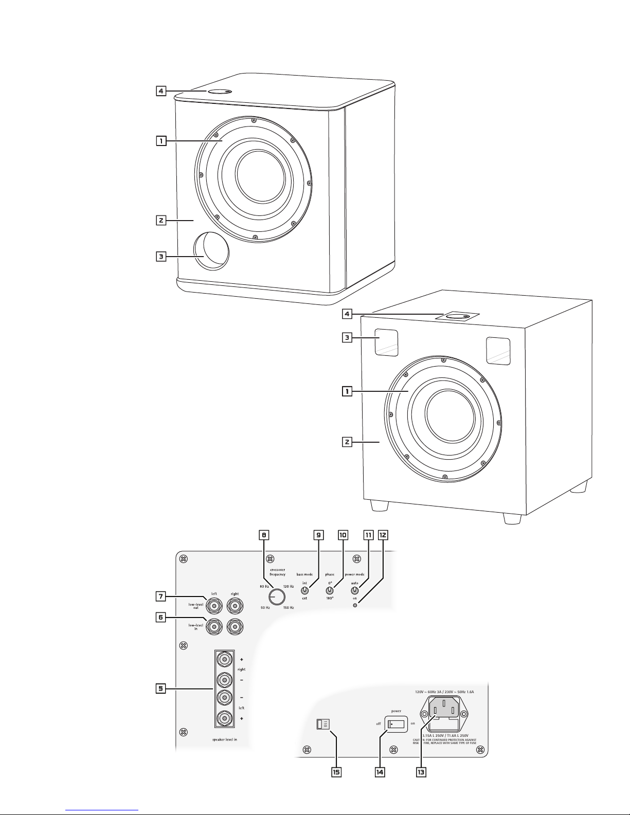
Amplifier Panel
Controls and Connections

5
FEATURES
1Bass Driver
The Basis 300 and ICS 300 use a 10-inch (254mm)
custom-built long-throw driver with a treated paper cone
and a die-cast aluminum chassis.
2Handmade Cabinets
Snell cabinets are hand-assembled with exceptional
workmanship to ensure sharp corners and smooth sides.
The wood veneers of the Basis 300 are hand sanded
several times before the final finish is applied. Even the
black finish of the ICS 300 is applied with uncompromis-
ing attention to detail.
3Bass Reflex Ports
Provide maximum extended bass response. The ports in
each model are specifically tuned to provide the best
possible performance with the driver, cabinet and likely
placement.
4Bass Level Control
The Bass Level control adjusts the output level of the
subwoofer. It is located for easy access to make it easy
to achieve the correct balance between the subwoofer
and the main speakers. A typical setting for the control
is around the 12 o’clock position.
5Speaker Level Inputs
The Basis 300/IC-Basis 300 have high-level inputs that
can be used when preamp outputs/power amp inputs
are not available. The speaker output wires are attached
to four binding post connectors. They accept bare wire
or wire with terminals.
6Low Level Inputs
Use this input when your system has preamp outs and
amplifier inputs.
7Low Level High Pass Outputs
These outputs provide the signal that goes to the power
amplifier that drives the main speakers in the system.
The signal from these outputs is high pass filtered
(80 Hz, 12 dB/octave) to remove bass sounds.
8Crossover Frequency Control
This control sets the frequency of the low-pass filter,
and is fully adjustable from 50 to 150Hz. Bass sound
below the frequency set by the control are directed to
the Basis 300 / IC-Basis 300 amplifier and speaker.
9Bass Mode Switch
Set the switch to INT to use the Basis 300/IC-Basis 300
internal crossovers and the Crossover Frequency and
Bass Level controls. Setting the switch to EXT bypasses
the internal crossover and controls. Use this setting
when the subwoofer is connected to electronics that
controls these functions, such as in THX® systems.
0Phase Switch
Determines whether the subwoofer adds or cancels in
the crossover region. The proper setting changes based
upon the current location of the speaker. Use the setting
that produces the smoothest, most consistent sound
through the crossover region.
-Power Mode Switch
When the switch is set to Auto, the amplifier will power up
when it senses an input signal. If no input signal is present,
the amplifier switches to low power standby mode after
8-10 minutes. When the switch is in the On position the
automatic power on/standby feature is disabled and the
subwoofer amplifier is always on.
=Power Mode Indicator Light (IC-Basis 300 only)
This LED lights when the amplifier is on.
qPower Input Connector
Plug the power cord into this connector and the wall
power outlet.
wPower Switch
This switch turns the power to the subwoofer on and
off. Usually the only time the main power switch should
be turned off is when the subwoofer will not be used for
an extended period of time, such as when you are away
on a vacation.
Warning: To reduce the risk of electric shock, always
switch off the subwoofer and the amplifier and or
receiver when making connections to the subwoofer and
speakers.
eLine Voltage Selector Switch
Set this switch to the power line voltage – 115 V or
230 V – in your location.
Warning: Turn the power switch wof the Basis 300/
IC-Basis 300 before changing the setting of this switch.

6
Subwoofer Input Connection
Some receivers, amplifiers or sound processors have
low-level, monophonic subwoofer outputs. If your
equipment has this type of an output, conect it to either
of the Low Level inputs. Be sure to set the Bass Mode
switch 9to EXT.
Note: When the Bass Mode switch is set to the EXT posi-
tion the subwoofers Crossover Frequency control 8and
the Level Control 4are bypassed. The electronics sup-
plying the signal controls the crossover frequency and
the subwoofer level. If the crossover frequency of the
component providing the subwoofer output signal is not
adjustable, it may not produce the best subwoofer-to-
main speaker transition. In such cases it is better to use
a full-range low level input from the source electronics
and let the subwoofer amplifier control the crossover.
Low Level Connection
Whenever possible connect the subwoofer to
the system through low level (also called line
level) input and output connections. Even if you
do not have a separate preamp and power amp,
many receivers and integrated amplifiers include
Preamp Out and Amplifier In connectors.
Connect the Preamp Outputs of your system to
the Low Level In connectors of the subwoofer
amplifier. When using the low level connec-
tions, the signal from the High Pass Outputs is
returned to your amplifier which will drive the main
speakers in the system. This output is high pass filtered
to remove sound below frequency set by the Crossover
Low Pass Filter Control. See the Fine Tuning section of
this manual for more information.
CONNECTION
Amplifier, Receiver or
Preamp/Power Amp
Subwoofer
Amplifier
PREAMP
OUT
AMP
IN
L
R
Subwoofer
Amplifier Amplifier, Receiver or
Sound Processor
Use either
low level
input
SUB
OUT
7
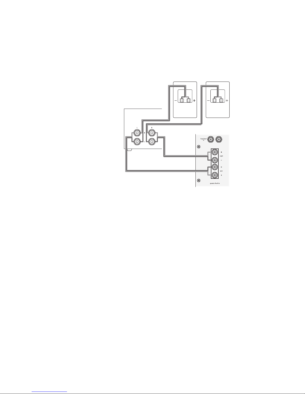
High Level Connection
If the electronics in your system does not have a
preamp level output, the subwoofer can be connected
to speaker outputs using the Speaker Level Inputs. The
Subwoofer amplifier has speaker wire binding posts,
the type found on many amplifiers. They can accept
ether bare wires or wires terminated with lugs.
To attached the bare wires to the connector, strip off
about 3/8” (8mm) of the insulation. Twist the wire
strands into a bundle. Make sure their are no loose
strands. Unscrew the terminal to expose the hole in the
center shaft of the terminal. Insert the wire into the
hole. Turn the terminal to clamp the wire in place.
If the wires are terminated with lugs, simply unscrew
the terminal and insert the lug. Turn the terminal to
clamp the lug in place.
NOTE: Be sure to maintain proper polarity — that is
connect + to + (positive to positive) and – to - (nega-
tive to negative). All wire has one conductor marked in
some way to make it easy to trace the connections. Typi-
cally there is a stripe on the insulation or a rib molded
into it. Or the insulation will be transparent and the wire
strands of one conductor will be copper colored and the
other will be silver colored.
With a Speaker Level Input connection both the sub-
woofer and the main speakers are connected directly
to the amplifier. Consequently the main speakers will
operate full range. Take this into account when setting
the crossover frequency of the subwoofer. The crossover
frequency should be set at approximately the same
frequency where the bass response of the main speakers
starts to decrease. That will avoid a situation where both
the main speakers and the subwoofer are reproducing
a part of the bass range, which would produce an un-
natural sound.
In addition to the connection method shown above you
may also connect the amplifier to the main speakers and
then run extension wires from the main speakers to the
subwoofer. Which one you use will depend largely on
you physical set up of your room.
Subwoofer Amplifier
Amplifier or Receiver
Left Main
Speaker
Right Main
Speaker

8
PLACEMENT
• Carefullyreinstallthemountingscrews.Replacethe
screws in the corners first, driving them in just until
they are lightly set. Then reinstall the remaining
screws in the same way. Then, working from side-
to-side and corner-to-corner, gradually tighten the
screws until they are all firmly set. Be sure not to
over-tighten the screws.
• Carefullyrollthecabinetontoitsfeet.Reconnect
the volume control. Connect the wires to the driver
– be sure the red and black wires are attached to
the respective red and black speaker terminals.
• Besurethegasketaroundthecoverplateinstalla-
tion hole is set properly, then set the plate in place.
Carefully reinstall the mounting screws using the
same procedure described for the amplifier mount-
ing screws.
Standard Front
Firing Configuration
Reconfigured
for Downward Firing
Basis 300
Typically the Basis 300 will produce the smoothest
response when placed against a wall. Placement in a
corner can enhance audible bass output. This may allow-
ing you to run operate the subwoofer at a lower power
level. However in some case corner placement will result
in “thick” or “heavy” sounding bass. Experiment with
subwoofer placement while at the same time adjusting
crossover frequency, output level, and phase. (See sec-
tion on Fine-Tuning The Subwoofer.)
IC-Basis 300
The IC-Basis 300 is engineered for the boundaries and
conditions found in cabinets and millwork. In addition it
can be configured so the driver is either front or down
firing. If the subwoofer is installed in a location where
the front of the cabinet is fully open to the listening
room, then the front firing configuration may be used.
If the subwoofer is installed in a location where the
front of the cabinet and driver are not fully open to the
listening room, then reconfiguring the subwoofer for
downward firing will probably produce better perfor-
mance.
Reconfiguring the IC-Basis 300
• Carefullylaythesubwooferinitsrightorleftside
on a surface that will not damage the cabinet.
• Removethefeetfromtheandthecoverplatefrom
the bottom of the cabinet. Disconnect the wires
from the amplifier to the subwoofer and volume
control. (Simply push in on the back of the speaker
terminals and pull out the wire and disconnect the
plug-in connector of the volume control wires.)
• Removescrewsaroundtheperipheryoftheampli-
fier, leaving the screws in the upper corners for last.
Then, while holding the amplifier in place, remove
the last two screws and the amplifier.
• Locatethevepilotholesaroundthedriver.
Reinstall the four feet previously removed and the
additional foot shipped with the unit.
• Carefullyrollthecabinetontowhatwillnowbe
the front surface, that is, the one with the volume
control. Be sure the gasket around the amplifier in-
stallation hole is set properly, then set the amplifier
in place.

9
The best way to determine the best location for the
subwoofer and the best settings for the various controls
is with the aid of electronic instrumentation such as a
sound spectrum analyzer. Your retail dealer may offer to
do this as a part of the installation process. If that is not
an option then systematic adjustment of the controls in
conjunction with careful listening tests can also produce
very good results.
Subwoofer Bass Level Control 4
The first step of the process is to choose a musical selec-
tion with a heavy and continuous bass line. Set the Bass
Level Control at its mid-rotation point and play a short
section several times until you have a firm impression of
it in your mind. Then try another raising or lowering the
Bass Level Control to see if it provides smoother or more
balanced response.
Repeat this process until you are content with the bal-
ance between the main speakers and the subwoofer.
Avoid the tendency to set the control so it produces
“impressive” bass output. Strive for a balanced, natural
sound. How the system sounds with a male speaking
voice is a good indicator of how well the main speaker-
to-subwoofer balance is set.
Crossover Frequency Control 8
The goal in setting the Crossover Frequency control is
to make the transition from the main speakers to the
subwoofer as smooth as possible.
NOTE: If the electronics in your system has a subwoofer
output you can skip this section. Set the Bass Mode
switch 9to EXT and adjust the crossover frequncy
with the system electronics. In some cases the crossover
frequency of the external electronics may not be adjust-
able and may not produce the best subwoofer-to-main
speaker transition. In such cases it is better to use a full-
range low level input from the source electronics and let
the ICS 300 or Basis 300 control the crossover.
When Using the Low Level Inputs
If you are using the Low Level Inputs and returning
the high-pass filtered signal to the amplifier (see the
diagram on page 6), begin by setting the crossover at
100Hz – with the control knob indicator at the one
o’clock position. Some rooms naturally overemphasize
bass in this region, creating an undesirable ”bump“ or
”boomy“ quality in the sound. If this is the case with
your room, try turning the crossover down to 80Hz. On
the other hand‚ some rooms have a natural tendency to
”swallow up“ the bass in the 100Hz region, causing the
sound to appear thin. In rooms of this type, try setting
the crossover at 120Hz. This may help to round out the
overall sound.
When Using the Speaker Level Inputs
If you are running your main speakers full range, set
the crossover close to the bass cut-off frequency of
your main speakers. See the specifications for your
main speakers for information. This will help achieve a
smooth, seamless blend between your speakers and the
subwoofer. Experiment until you are happy with the
main speaker-to-subwoofer transition.
Control Interaction
There is significant interaction between the Crossover
Frequency control and the Bass Level control. This
interaction affects the sound in the midbass range
where the transition from the main speakers to the
subwoofer occurs. If you are hearing too much midbass,
adjust the Crossover Frequency control to a lower set-
ting and increase the Bass Level control. This decreases
midbass output while increasing the amount of lower
bass energy. Conversely, turning down the Bass Level
control while setting the Crossover Frequency control
to a slightly higher setting will increase the ratio of
mid bass-to-low bass sound. The result will be a sound
with a ”quick“ quality. Experiment while listening to a
variety of sources. Adjust the subwoofer controls until
you achieve a smooth and seamless blend with the main
speakers .
FINE TUNING THE SUBWOOFER

10
Setting the Phase
The proper setting for the Phase Switch 0changes
based upon the location of the speaker. To determine
the correct setting for your room, use a source with
a full and continuous bass line. Have a second person
repeatedly switch the Phase Switch from one position to
the other. You will notice that one position will deliver
stronger midbass sound. This is the proper position for
the Phase Switch. If the midbass now seems too promi-
nent, compensate by slightly lowering the crossover
frequency or the output level.
How To Care For Your Speakers
➤Use a soft terry cloth towel slightly dampened with
water, glass cleaner, or a diluted mild detergent. The
towel should be just damp enough to wipe the surface
clean without leaving a trail of moisture.
➤Do not use abrasive cleaners or any cleaner contain-
ing chemicals harsher than those found in glass cleaner.
LIMITED WARRANTY
During the warranty period, Snell Acoustics will repair,
for the original owner, any defect in materials or
workmanship that occurs in normal use of the speaker
system, without charge for parts and labor. The war-
ranty period for all parts of the subwoofer, except the
amplifier, is five (5) years. The warranty period on the
amplifier is one (1) year.
Your responsibilities are to use the product according
to the instructions supplied, to provide safe and secure
transportation to an authorized Snell Acoustics service
representative, and to present proof of purchase from
an authorized Snell dealer in the form of your sales slip
when requesting service.
Excluded from this warranty is damage that results
from abuse, misuse, accidents, shipping, repairs, or
modifications by anyone other than an authorized Snell
Acoustics service representative. This warranty is void if
the serial number has been removed or defaced.
This warranty gives you specific legal rights, and you
may also have other rights that vary from state to state.
If Service Seems Necessary
Contact the dealer from whom you purchased the
speaker system. If that is not possible, call us at
978-538-6262, or write to:
Snell Acoustics
300 Jubilee Drive, P.O. Box 3717
Peabody, MA 01961-3717
We will promptly advise you of what action to take. If it
is necessary to return your speaker system to the factory,
please ship it prepaid in the original factory packaging.
Please note that Snell Acoustics will not be held liable
for shipping damage due to improper packaging. After
it has been repaired, we will return it freight-prepaid in
the U.S. or Canada.


300 Jubilee Drive, P.O. Box 3717
Peabody, MA 01961-3717
phone: 978-538-6262
fax: 978-538-6266
email: info@snellacoustics.com
web: www.snellacoustics.com
©2006 Snell Acoustics.
All Rights Reserved.
Specifications are subject
to change without notice.
Covered by patents issued
and or pending.
Part #542-1062
This manual suits for next models
1
Table of contents
Other Snell Subwoofer manuals

Snell
Snell PS.10mk2 User manual

Snell
Snell ICS Sub 12 User manual

Snell
Snell ICS Sub300 User manual

Snell
Snell AMC Sub 10 User manual

Snell
Snell Premier Basis 300 User manual

Snell
Snell Premier Basis 150 User manual

Snell
Snell QBx Sub User manual

Snell
Snell ICS Sub 24 mk3 User manual

Snell
Snell ICS Sub 300 User manual

Snell
Snell AMS Sub 10 User manual


