manuals.online logo
Brands
  1. Home
  2. •
  3. Brands
  4. •
  5. aFe Power
  6. •
  7. Automobile Accessories
  8. •
  9. aFe Power Scorpion User manual

aFe Power Scorpion User manual

advanced FLOW engineering
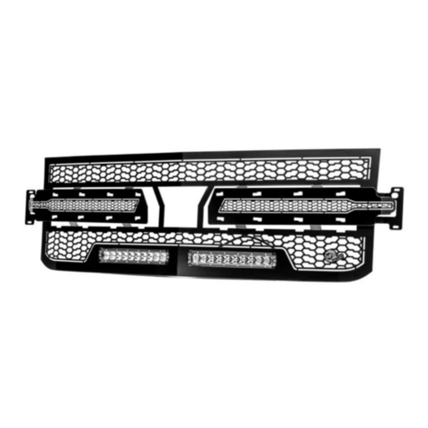
Instruction Manual P/N: 79-21007L
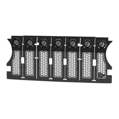
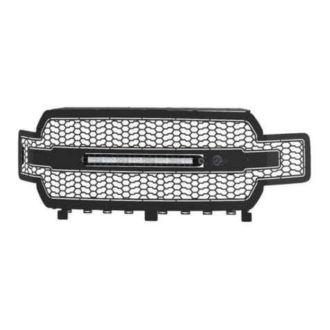
Scorpion Grille
Make: Ram Model: 1500 Year: 2019-2020
1
•Please read the entire instruction before proceeding.
•Ensure all components listed are present.
•Ensure you have all necessary tools before proceeding.
•Disconnect the negative battery terminal before proceeding.
•If you are missing any of the components, call customer support 951 493 7100
Label
Qty.
Description
A
1
aFe Scorpion Grille
B
1
20” Single Row LED
C
8
Brackets, “C”
D
2
Lock nut, 1/4”-20 Nylon
E
2
Washer, 1/4" Flat
F
8
Lock Nut, #10-32 Nylon
G
5
Nut, #10-32 Flange SS
H
5
Screw, #10-32 x 1/2” Button Head (black)
I
2
Bracket, LED #1
J
1
aFe Logo Back Plate
K
1
Power Harness
L
15
Ties, Cable
•Applications models vary. We recommend verifying fitment before beginning installation process.
•Images featured in the instruction documents may not always exactly match your grille.
•This part fits on: (Ram 1500) Laramie, Big Horn, & Trademan models.
•This part does not fit: (Ram 1500) Sport, Rebel, Laramie Longhorn, Limited
2
3
Note: Before you begin, use “Painter’s Tape” to apply a protective guard around the work
areas (fender and bumper valance). This will help protect the paint and finish of your vehicle.
1. Disconnect the negative battery terminal.
2. Locate twelve (12) plastic clips on top of plastic radiator cover. Carefully pry the pins out to
remove and then set aside. Save all parts for reinstallation.
3. Remove the plastic radiator cover. Set it aside for reinstallation.
4
4. Remove the twelve (12) bolts that attach the factory grille assembly to the core support.
Save for reinstallation.
5
Note: Use “Painter’s Tape” to apply a protective guard around the work areas (fender and
Front bumper fascia). This will help protect the paint and finish of your vehicle.
Note: It may be easier to remove the tire and the wheel well from the truck.
5. Remove the four (4) screws from the front of the wheel well on both sides of the vehicle.
6. Carefully pull the wheel well down far enough to expose the back side of the bumper and
the inside of the fenders.
6
7. Remove the one (1) bolt located on the inside of the fender on both sides of the vehicle.
The bolt connects the fender to the bumper fascia. Save for reinstallation.
7
Note: Use “Painter’s Tape” to apply a protective guard around the work areas (fender and
Front bumper fascia). This will help protect the paint and finish of your vehicle.
8. Disconnect the four (4) clips for the wheel arch moldings. Squeeze the clip from inside the
fender to get them to release easier.
8
Note: Please go slow and use extreme caution while performing the following steps.
Note: Use “Painter’s Tape” to apply a protective guard around the work areas (fender and
Front bumper fascia). This will help protect the paint and finish of your vehicle.
9. Using a plastic prying tool, carefully separate the front bumper fascia from the fender. After
separating the fender from the bumper fascia, gently pull the bumper fascia and remove it
from the headlight and the grille. Save for reinstallation.
10. Repeat Step 9 on the opposite side of the vehicle.
9
11. Remove three (3) bolts (on both sides of the vehicle) that retain the grille under the
headlight. Save for reinstallation.
10
12. Lift the grille up off the headlight tabs and pull gently away from the truck. Remove the
factory grille assembly from the vehicle.
11
Note: To prevent scratching painted parts use protective covering between the grille and a
flat surface.
13. Remove the nine (9) bolts from the factory grille assembly and discard.
12
Note: To prevent scratching painted parts use protective covering between the grille and a
flat surface.
14. Disconnect the clips that secure the factory outer grille to the factory inner grille. Remove
the factory outer grille and discard. Save the inner grille for reinstalltion.
13
15. Remove and discard the two (2) nuts from the supplied 20” single row LED light.
14
Note: Please read the instruction below prior to installation.
16. Locate the drilled hole furthest to the driver’s side. Install one (1) supplied #10-32 x 1/2”
button head screw (black) thru the front of the aFe Scorpion grille. Turn the aFe Scorpion
grille over and install the aFe logo back plate onto the #10-32 x 1/2” button head screw
(black). Install one (1) supplied #10-32 SS flange nut onto the #10-32 x 1/2” button head
screw (black). Snug the #10-32 flange nut up but do not tighten.
17. Install the supplied 20” single row LED light through the front of the aFe Scorpion grille.
While holding the 20” single row LED light, install two (2) supplied #1 LED bar brackets
(bracket feet point away from each other) from the back of the aFe Scorpion grille and onto
the studs on the 20” single row LED light. Install the two (2) supplied 1/4" washers (black)
and two (2) supplied 1/4"-20 nylon lock nuts (black) onto the light. Do not tighten. From the
front, install four (4) #10-32 x 1/2” button head screws (black) through the aFe Scorpion
grille. Turn the aFe Scorpion grille around and make sure that the driver’s side #10-32 x 1/2”
button head screws (black) pass thru the aFe logo back plate and thru the #1 LED bracket.
The passenger side runs thru the #1 LED bracket only. Install four (4) #10-32 SS flange nut
onto the #10-32 x 1/2” button head screws (black). Tighten the #1 LED brackets first. Then
tighten the 20” single row LED light while centering it.
15
18. Install the factory inner grille onto the aFe Scorpion grille. The studs on the aFe Scorpion
grille come through the open locations where the outer grille was clipped. Push the factory
grille over the studs. Install the eight (8) supplied “C” brackets onto the studs. Install the
eight (8) supplied #10-32 nylon lock nuts onto the studs. Before tightening the #10-32 nylon
lock nuts, center the grille.
16
19. Before installing the aFe Scorpion grille, install the supplied power harness. The red wire
goes on the positive battery terminal (+) and the black wire goes on the negative battery
terminal (-). You will need to mount the switch inside the cab or to an available prewired
switch. Use the (15) supplied 8” cable ties to secure the wiring loom to the vehicle.
17
20. Install the aFe Scorpion grille assembly onto the vehicle.
21. Plug the 20” Single Row LED light into the power harness.
22. Install the three (3) bolts removed in Step 11 (on both sides of the vehicle) that retain the
grille under the headlight.
18
Note: Remove all the painter’s tape prior to reinstalling the painted parts.
23. Reinstall the bumper fascia’s removed in Step 10 (on both sides of the vehicle). Push the
bumper fascia’s in till they are clipped in securely into the aFe Scorpion grille assembly.
19
Note: Remove all the painter’s tape prior to reinstalling the painted parts.
24. Reinstall the wheel arch moldings into the bumper fascia and the fenders (on both sides of
the vehicle).

This manual suits for next models

1

Other aFe Power Automobile Accessories manuals
aFe Power advanced FLOW engineering User manual

aFe Power

aFe Power advanced FLOW engineering User manual

aFe Power 54-12208 User manual

aFe Power

aFe Power 54-12208 User manual

aFe Power 440-401006-N User manual

aFe Power

aFe Power 440-401006-N User manual

aFe Power SCORCHER BLUE 77-83043 User manual

aFe Power

aFe Power SCORCHER BLUE 77-83043 User manual

aFe Power Momentum GT User manual

aFe Power

aFe Power Momentum GT User manual

aFe Power 56-70058D User manual

aFe Power

aFe Power 56-70058D User manual

aFe Power 77-43025 User manual

aFe Power

aFe Power 77-43025 User manual

aFe Power 77-47001 User manual

aFe Power

aFe Power 77-47001 User manual

aFe Power 46-39102 User manual

aFe Power

aFe Power 46-39102 User manual

aFe Power 46-71110A User manual

aFe Power

aFe Power 46-71110A User manual

aFe Power 46-70049 User manual

aFe Power

aFe Power 46-70049 User manual

aFe Power Takeda 56-10005D User manual

aFe Power

aFe Power Takeda 56-10005D User manual

aFe Power 46-71180A User manual

aFe Power

aFe Power 46-71180A User manual

aFe Power Magnum FORCE 54-13035D User manual

aFe Power

aFe Power Magnum FORCE 54-13035D User manual

aFe Power 54-10468 User manual

aFe Power

aFe Power 54-10468 User manual

aFe Power Momentum hd User manual

aFe Power

aFe Power Momentum hd User manual

aFe Power SCORPION 79-21003L User manual

aFe Power

aFe Power SCORPION 79-21003L User manual

aFe Power 77-46306 User manual

aFe Power

aFe Power 77-46306 User manual

aFe Power Scorpion 79-21001L User manual

aFe Power

aFe Power Scorpion 79-21001L User manual

aFe Power 77-42008 User manual

aFe Power

aFe Power 77-42008 User manual

aFe Power dfs780 User manual

aFe Power

aFe Power dfs780 User manual

aFe Power 52-10002D User manual

aFe Power

aFe Power 52-10002D User manual

aFe Power takeda 56-70043D User manual

aFe Power

aFe Power takeda 56-70043D User manual

aFe Power 57-10018D User manual

aFe Power

aFe Power 57-10018D User manual

Popular Automobile Accessories manuals by other brands

Car-Interface CI-RL3-MIB-TT-LA manual

Car-Interface

Car-Interface CI-RL3-MIB-TT-LA manual

Thule TRAILWAY 959 user manual

Thule

Thule TRAILWAY 959 user manual

Alpine HCE-C115 owner's manual

Alpine

Alpine HCE-C115 owner's manual

Quadratec QRC installation manual

Quadratec

Quadratec QRC installation manual

Road Shower 4 owner's manual

Road Shower

Road Shower 4 owner's manual

Southern Car Parts C6 Tail Light Seal installation instructions

Southern Car Parts

Southern Car Parts C6 Tail Light Seal installation instructions

Mile Marker PE2000 Installation and operation manual

Mile Marker

Mile Marker PE2000 Installation and operation manual

Thule Kit 2032 installation instructions

Thule

Thule Kit 2032 installation instructions

Directed VOXX DEI 933.VW14 v2.11.198.12 installation guide

Directed

Directed VOXX DEI 933.VW14 v2.11.198.12 installation guide

Brink 2204 Fitting instructions

Brink

Brink 2204 Fitting instructions

Thule Rapid System 1100 Fitting instructions

Thule

Thule Rapid System 1100 Fitting instructions

Waeco DC-Kit3 Installation and operating manual

Waeco

Waeco DC-Kit3 Installation and operating manual

OEM Audio Reference 400CF manual

OEM Audio

OEM Audio Reference 400CF manual

Technaxx BT-X30 user manual

Technaxx

Technaxx BT-X30 user manual

ConWys AG 16250520C Fitting instructions

ConWys AG

ConWys AG 16250520C Fitting instructions

Metra Electronics 99-3010S installation instructions

Metra Electronics

Metra Electronics 99-3010S installation instructions

ACPS oris 037-251 FITTING INSTRUCTION

ACPS

ACPS oris 037-251 FITTING INSTRUCTION

rockymounts TieRod installation manual

rockymounts

rockymounts TieRod installation manual

manuals.online logo
manuals.online logoBrands
  • About & Mission
  • Contact us
  • Privacy Policy
  • Terms and Conditions

Copyright 2025 Manuals.Online. All Rights Reserved.