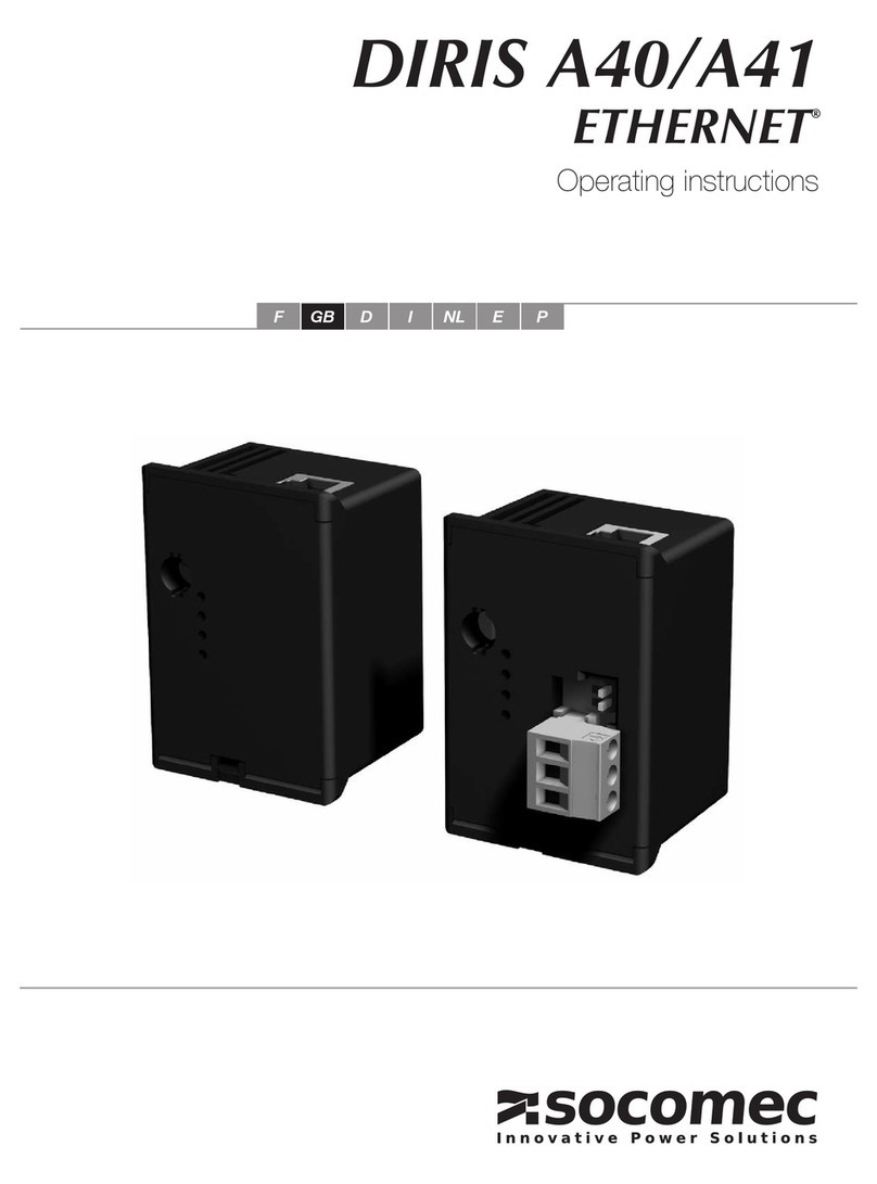
socomec DIRIS A41 User manual

DIRIS A40/A41
RS485 – JBUS/MODBUS®
Operating instructions
F GB D I NL E P

2DIRIS A40/A41 - Ref.: 536 103 B GB 3
DIRIS A40/A41 - Ref.: 536 103 B GB
PRELIMINARY OPERATIONS _______________________________________________ 4
GENERAL INFORMATION ______________________________________________ 4
INSTALLATION ____________________________________________________________ 5
CONNECTION ________________________________________________________ 5
PROGRAMMING___________________________________________________________ 6
COMMUNICATION ADDRESS __________________________________________ 7
COMMUNICATION SPEED _____________________________________________ 7
COMMUNICATION PARITY _____________________________________________ 8
COMMUNICATION STOP BIT ___________________________________________ 8
COMMUNICATION _________________________________________________________ 9
THE STANDARD COMMUNICATIONS FRAME ____________________________ 9
A : NEW COMMUNICATION TABLE FROM 01/2009 __________________________ 10
1 > TABLE C550 Hex : Main measurements allocated from current transformer
and voltage transformer values __________________________________________ 10
2 > TABLE C650 Hex : Energy monitoring _____________________________________ 11
3 > TABLE C750 Hex : Additional measurements allocated from current transformer
and voltage transformer values __________________________________________ 11
4 > TABLE C850 Hex : Main measurements not allocated from current transformer
and voltage transformer values __________________________________________ 12
5 > TABLE C900Hex : Temperature measurements_______________________________ 13
6 > TABLE C950Hex : Harmonics ___________________________________________ 13
7> TABLEE000Hex:Primaryconguration ___________________________________ 19
8> TABLEE110Hex:Ethernetconguration __________________________________ 20
9>TABLEE200Hex:Ethernetconguration ___________________________________ 21
B : OLD COMMUNICATION TABLE BEFORE 01/2009 ________________________ 22
LIST OF PARAMETERS TO BE DISPLAYED _____________________________ 22
Table of values with allocated current and voltage winf-ding ratios on 2 words __________22
Address available with the Monitoring or Control/Command option ____________________24
Instant value display _____________________________________________________________24
Table of values without allocated current and voltage winding ratios on 1 word _________ 25
Alarm event log__________________________________________________________________28
Table of current and voltage harmonics_____________________________________________45
Option recognition table __________________________________________________________48
LIST OF PARAMETERS TO BE DISPLAYED OR PROGRAMMED ___________ 49
RESET TO ZERO: ENERGY METERS AND MAX. VALUES_________________ 60
SAVED COMMAND ___________________________________________________ 61
PULSE METERS VALUES _____________________________________________ 61
DATE AND HOUR SETTINGS __________________________________________ 62
LAST 10 ALARMS EVENT LOG ________________________________________ 62
LAST 10 VOLTAGE DIPS EVENT LOG / SAG_____________________________ 84
LAST 10 VOLTAGE SURGE EVENT LOG / SWELL ________________________ 84
MINIMUM AND MAXIMUM INSTANTANEOUS VALUES ___________________ 89
LAST 10 VOLTAGE CUT-OFFS EVENT LOG / SAG _______________________ 93
MEAN POWER EVENT LOG ___________________________________________ 95
MEAN VOLTAGE EVENT LOG __________________________________________ 95
MEAN FREQUENCY EVENT LOG ______________________________________ 95
TECHNICAL CHARACTERISTICS __________________________________________ 96
GLOSSARY OF ABBREVIATIONS __________________________________________ 96
Contents
GB

DIRIS A40/A41 - RS485 - JBUS/MODBUS®
GB
DIRIS A40/A41 - RS485 - JBUS/MODBUS®
4DIRIS A40/A41 - Ref.: 536 103 B GB 5
DIRIS A40/A41 - Ref.: 536 103 B GB
PRELIMINARY OPERATIONS
Functions
The optional IP Communication module must be
connected to the DIRIS A40/A41 (réf. : 4825 0201,
4825 0202, 4825 1201, 4825 1202, 4825 U201, 4825
0207, 4825 0211, 4825 0213, 4825 0214). It pro-
vides an RS485 serial link (2 or 3 wires) with JBUS/
MODBUS®protocol for the use of DIRIS A40/A41 from
a PC or PLC.
General points
Forastandardconguration,anRS485linkisusedto
connect up to 31 DIRIS or COUNTIS Ciwith a PC or
a PLC over a distance of 1200 metres, using JBUS/
MODBUS©protocol.
DIRIS 109 E F
DIRIS 110 E F
Recommendations:
You should use a shielded twisted pair (LIYCY type). In
a disturbed environment or large network (in terms of
length) we recommend the use of a shielded twisted
pair (type LIYCY-CY).
A repeater (1 channel) or an arrestor (4 channels)
should be used if you intend to exceed the distance
(1200 m) and/or maximum number (31) of DIRIS.
Please contact us for more information.
NB :
A 120 ohm resistance (found on the additional module)
must be xed at both ends of the link.
Other solutions are available (modem, optical bre, etc.).
Please contact us.
GENERAL INFORMATION
CONNECTION
ThemoduleisttedontothebackoftheDIRIS A40/A41 in one of the 4 positions provided.
DIRIS 342 A
1
NO
1
DIRIS 347 A
3
DIRIS 343 A
2Fix the module in one of the four positions.
4Follow indications when connecting the terminal.
Switch on voltage supply.
INSTALLATION
For personnel and product safety please read the
contents of these operating instructions carefully
before connecting.
Check the following points as soon as you receive the
DIRIS A40/A41 package:
•thepackingisingoodcondition,
•theproducthasnotbeendamagedduringtransit,
•the product reference number conforms to your
order,
•thepackagecontainsthe productandtheoperating
instructions.
The DIRIS A40/A41 must be switched off

DIRIS A40/A41 - RS485 - JBUS/MODBUS®
GB
6DIRIS A40/A41 - Ref.: 536 103 B GB 7
DIRIS A40/A41 - Ref.: 536 103 B GB
PROGRAMMING
PROGRAMMING
Previous menu
Following menu
p.81
p.81
p.82
p.82
COMMUNICATION ADDRESS
>
Example : COM ADR = 7
x 3
x 2
x 1
conrm
COMMUNICATION SPEED
>
Example : BDS = 19 200 bauds
x 1
x 1
x 1
conrm

DIRIS A40/A41 - RS485 - JBUS/MODBUS®
GB
DIRIS A40/A41 - RS485 - JBUS/MODBUS®
8DIRIS A40/A41 - Ref.: 536 103 B GB 9
DIRIS A40/A41 - Ref.: 536 103 B GB
PROGRAMMING COMMUNICATION
COMMUNICATION PARITY
>
Example : PAR = Even
x 1
x 1 (Odd)
x 2 (Even)
x 3 (No)
COMMUNICATION STOP BIT
>
Example : STOP = 2
x 1
x 1
conrm
The JBUS/MODBUS®used by the DIRIS A40/A41
involves a dialogue using a master-slave hierarchical
structure. There are two possible dialogues:
•themastercommunicateswith aslave(DIRIS) and
waits for its reply
•themastercommunicateswithalltheslaves(DIRIS)
without waiting for their reply.
The mode of communication is the RTU (Remote
Terminal Unit) using hexadecimal characters of at least
8 bits.
According to the JBUS/MODBUS®protocol, transmis-
sion time must be less than 3 silences, i.e. the emission
time of 3 characters so that the message is processed
by the DIRIS.
To correctly use information, the following functions
are important:
3 : to read n words (maximum 128).
6 : to write one word.
8 : to diagnose exchanges between the master and the
slave via meters 1, 3, 4, 5 and 6.
16 : to write n words (maximum 128).
NB:
When selecting slave address 0, a message is sent to
all the instruments present on the network (only for
functions 6 and 16).
Comment :
The response time (time out question/answer) is 250 ms
maximum
THE STANDARD COMMUNICATIONS FRAME
Slave address Function code Address Data CRC 16
The standard communications frame consists of:
x 1 (2 bits)
x 2 (1 bits)

DIRIS A40/A41 - RS485 - JBUS/MODBUS®
GB
10 DIRIS A40/A41 - Ref.: 536 103 B GB 11
DIRIS A40/A41 - Ref.: 536 103 B GB
COMMUNICATION
A : NEW COMMUNICATION TABLE FROM 01/2009
These new tables are available for all new Socomec products on sale from January 2009. The aim is to have common
tables for common values, irrespective of the Socomec product. We recommend that you use these new tables whe-
never possible for developing your applications.
A : NEW COMMUNICATION TABLE FROM 01/2009
2 > TABLE C650 Hex : Energy monitoring
Decimal Hex. No. of Description Unit JBUS function
address address words available
50768 C650 2 hour meter 1/100 h 3
50770 C652 2 Reserved for manufacturer - 3
50772 C654 2 Reserved for manufacturer - 3
50774 C656 2 Reserved for manufacturer - 3
50776 C658 2 Reserved for manufacturer - 3
50778 C65A 2 Reserved for manufacturer - 3
50770 C652 2 active energy + kWh 3
50772 C654 2 reactive energy + kvarh 3
50774 C656 2 apparent apparente kVAh 3
50776 C658 2 active energy - kWh 3
50778 C65A 2 active energy + kWh 3
50780 C65C 2 No. Compteurs d’Impulsions - 3
50782 C65E 2 pulse meter 1 - 3
50784 C660 2 pulse meter 2 - 3
50786 C662 2 pulse meter 3 - 3
50788 C664 2 pulse meter 4 - 3
50790 C666 2 pulse meter 5 - 3
50792 C668 2 pulse meter 6 - 3
50794 C66A 2 Reserved for manufacturer - 3
50796 C66C 2 Reserved for manufacturer - 3
50798 C66E 2 Reserved for manufacturer - 3
50800 C670 2 Reserved for manufacturer - 3
50802 C672 2 S Predicted active power kW/100 3
50804 C674 2 S Predicted reactive power kvar/100 3
50806 C676 2 S Predicted apparent power kVA/100 3
50808 C678 2 Ea+ between 2 tops 0,1 Ws 3
50810 C67A 2 Ea- between 2 tops 0,1 Ws 3
50812 C67C 2 Er+ between 2 tops 0,1 vars 3
50814 C67E 2 Er- between 2 tops 0,1 vars 3
50816 C680 2 Reserved for manufacturer - 3
50816 C680 1 Reserved for manufacturer - 3
50817 C681 1 Reserved for manufacturer - 3
3 > TABLE C750 Hex : Additional measurements allocated from CT values (current transformer) and VT
(voltage transformer) values
Decimal Hex. No. of Description Unit JBUS function
address address words available
51024 C750 2 avg U12 V/100 3
51026 C752 2 avg U23 V/100 3
51028 C754 2 avg U31 V/100 3
51030 C756 2 avg V1 V/100 3
51032 C758 2 avg V2 V/100 3
51034 C75A 2 avg V3 V/100 3
51036 C75C 2 avg F Hz/100 3
51038 C75E 2 avg I1 mA 3
51040 C760 2 avg I2 mA 3
51042 C762 2 avg I3 mA 3
51044 C764 2 avg In mA 3
51046 C766 2 avg
Σ
active power + kW/100 3
51048 C768 2 avg
Σ
active power - kW/100 3
51050 C76A 2 avg
Σ
reactive power + kvar/100 3
51052 C76C 2 avg
Σ
reactive power - kvar/100 3
51054 C76E 2 avg
Σ
apparent power kVA/100 3
51056 C770 2 max/avg U12 V/100 3
COMMUNICATION
1 > TABLE C550 Hex : Main measurements allocated from CT (current transformer) and VT (voltage
transformer) values
Decimal Hex. No. of Description Unit JBUS function
address address words available
50512 C550 2 hour meter 1/100 h 3
50514 C552 2 phase to phase voltage U12 V/100 3
50516 C554 2 phase to phase voltage U23 V/100 3
50518 C556 2 phase to phase voltage U31 V/100 3
50520 C558 2 phase to neutral voltage phase 1 V/100 3
50522 C55A 2 phase to neutral voltage phase 2 V/100 3
50524 C55C 2 phase to neutral voltage phase 3 V/100 3
50526 C55E 2 frequency Hz/100 3
50528 C560 2 phase current 1 mA 3
50530 C562 2 phase current 2 mA 3
50532 C564 2 phase current 3 mA 3
50534 C566 2 neutral current mA 3
50536 C568 2
Σ
active power +/- kW/100 3
50538 C56A 2
Σ
reactive power +/- kvar/100 3
50540 C56C 2
Σ
apparent power kVA/100 3
50542 C56E 2
Σ
power factor -: leading and + : lagging 0,001 3
50544 C570 2 active power phase 1 +/- kW/100 3
50546 C572 2 active power phase 2 +/- kW/100 3
50548 C574 2 active power phase 3 +/- kW/100 3
50550 C576 2 reactive power phase 1 +/- kvar/100 3
50552 C578 2 reactive power phase 2 +/- kvar/100 3
50554 C57A 2 reactive power phase 3 +/- kvar/100 3
50556 C57C 2 apparent power phase 1 kVA/100 3
50558 C57E 2 apparent power phase 2 kVA/100 3
50560 C580 2 apparent power phase 3 kVA/100 3
50562 C582 2 power factor phase 1 -: leading and + : lagging 0,001 3
50564 C584 2 power factor phase 2 -: leading and + : lagging 0,001 3
50566 C586 2 power factor phase 3 -: leading and + : lagging 0,001 3
50568 C588 2 Reserved for manufacturer - 3
50570 C58A 2 Reserved for manufacturer - 3
50572 C58C 2 Reserved for manufacturer - 3

DIRIS A40/A41 - RS485 - JBUS/MODBUS®
GB
12 DIRIS A40/A41 - Ref.: 536 103 B GB 13
DIRIS A40/A41 - Ref.: 536 103 B GB
Decimal Hex. No. of Description Unit JBUS function
address address words available
51058 C772 2 max/avg U23 V/100 3
51060 C774 2 max/avg U31 V/100 3
51062 C776 2 max/avg V1 V/100 3
51064 C778 2 max/avg V2 V/100 3
51066 C77A 2 max/avg V3 V/100 3
51068 C77C 2 max/avg F Hz/100 3
51070 C77E 2 max/avg I1 mA 3
51072 C780 2 max/avg I2 mA 3
51074 C782 2 max/avg I3 mA 3
51076 C784 2 max/avg In mA 3
51078 C786 2 max/avg
Σ
active power + kW/100 3
51080 C788 2 max/avg
Σ
active power - kW/100 3
51082 C78A 2 max/avg
Σ
reactive power + kvar/100 3
51084 C78C 2 max/avg
Σ
reactive power - kvar/100 3
51086 C78E 2 max/avg
Σ
apparent power kVA/100 3
51088 C790 1 Reserved for manufacturer - 3
51089 C791 1 Reserved for manufacturer - 3
51090 C792 1 Reserved for manufacturer - 3
51091 C793 1 Reserved for manufacturer - 3
51092 C794 1 Reserved for manufacturer - 3
51093 C795 1 Reserved for manufacturer - 3
COMMUNICATION
A : NEW COMMUNICATION TABLE FROM 01/2009
3 > TABLE C750 Hex (continued)
A : NEW COMMUNICATION TABLE FROM 01/2009
4 > TABLE C850 Hex
Decimal Hex. No. of Description Unit JBUS function
address address words available
51305 C869 1 phase power factor 1 -:
leading and + : lagging 0,001 3
51306 C86A 1 phase power factor 2 -:
leading and + : lagging 0,001 3
51307 C86B 1 phase power factor 3 -:
leading and + : lagging 0,001 3
51308 C86C 1 Reserved for manufacturer - 3
51309 C86D 1 Reserved for manufacturer - 3
51310 C86E 1 Reserved for manufacturer - 3
51311 C86F 1 Ea+ MWh 3
51312 C870 1 Reserved for manufacturer - 3
51313 C871 1 ER+ MWh 3
Decimal Hex. No. of Description Unit JBUS function
address address words available
51280 C850 1 hour meter h 3
51281 C851 1 phase to phase voltage U12 V/100 3
51282 C852 1 phase to phase voltage U23 V/100 3
51283 C853 1 phase to phase voltage U31 V/100 3
51284 C854 1 phase to neutral voltage 1 V/100 3
51285 C855 1 phase to neutral voltage 2 V/100 3
51286 C856 1 phase to neutral voltage 3 V/100 3
51287 C857 1 frequency Hz/100 3
51288 C858 1 phase current 1 mA 3
51289 C859 1 phase current 3 mA 3
51291 C85B 1 neutral current mA 3
51292 C85C 1
Σ
active power +/- kW/100 3
51293 C85D 1
Σ
reactive power +/- kvar/100 3
51294 C85E 1
Σ
apparent power +/- kVA/100 3
51295 C85F 1
Σ
power factor L/C -:
leading and + : lagging 0,001 3
51296 C860 1 phase active power 1 +/- kW/100 3
51297 C861 1 phase active power 2 +/- kW/100 3
51298 C862 1 phase active power 3 +/- kW/100 3
51299 C863 1 phase reactive power 1 +/- kvar/100 3
51300 C864 1 phase reactive power 2 +/- kvar/100 3
51301 C865 1 phase reactive power 3 +/- kvar/100 3
51302 C866 1 phase apparent power 1 kVA/100 3
51303 C867 1 phase apparent power 2 kVA/100 3
51304 C868 1 phase apparent power 3 kVA/100 3
4 > TABLE C850 Hex : Main measurements not allocated from CT values (current transformer) and VT
(voltage transformer) values
CAUTION : using this table involves multiplying values by transformation ratios.
5 > TABLE C900Hex : Temperature measurements
Decimal Hex. No. of Description Unit JBUS function
address address words available
51456 C900 1 Internal temperature sensor present
0 : no - 1 : yes - 3
51457 C901 1 Temperature module °C 3
51458 C902 1
External temperature sensors (1 to 5max)
- 3
51459 C903 1 extern temperature 1 °C 3
51460 C904 1 extern temperature 2 °C 3
51461 C905 1 extern temperature 3 °C 3
51462 C906 1 extern temperature 4 °C 3
51463 C907 1 extern temperature 5 °C 3
6 > TABLE C950Hex : Harmonics
Decimal Hex. No. of Description Unit JBUS function
address address words available
THD
51536 C950 1 thd U12 0,001 3
51537 C951 1 thd U23 0,001 3
51538 C952 1 thd U31 0,001 3
51539 C953 1 thd V1 0,001 3
51540 C954 1 thd V2 0,001 3
51541 C955 1 thd V3 0,001 3
51542 C956 1 thd I1 0,001 3
51543 C957 1 thd I2 0,001 3
51544 C958 1 thd I3 0,001 3
51545 C959 1 thd In 0,001 3
Current
51546 C95A 1 Max rank 3
51547 C95B 1
Harmonic
I1 row 3 0,001 3
51548 C95C 1 Harmonic I2 row 3 0,001 3
51549 C95D 1 Harmonic I3 row 3 0,001 3
51550 C95E 1 Harmonic IN row 3 0,001 3
51551 C95F 1 Harmonic I1 row 5 0,001 3
51552 C960 1 Harmonic I2 row 5 0,001 3
51553 C961 1 Harmonic I3 row 5 0,001 3
51554 C962 1 Harmonic IN row 5 0,001 3
51555 C963 1 Harmonic I1 row 7 0,001 3
COMMUNICATION

DIRIS A40/A41 - RS485 - JBUS/MODBUS®
GB
14 DIRIS A40/A41 - Ref.: 536 103 B GB 15
DIRIS A40/A41 - Ref.: 536 103 B GB
Decimal Hex. No. of Description Unit JBUS function
address address words available
51556 C964 1 Harmonic I2 row 7 0,001 3
51557 C965 1 Harmonic I3 row 7 0,001 3
51558 C966 1 Harmonic IN row 7 0,001 3
51559 C967 1 Harmonic I1 row 9 0,001 3
51560 C968 1 Harmonic I2 row 9 0,001 3
51561 C969 1 Harmonic I3 row 9 0,001 3
51562 C96A 1 Harmonic IN row 9 0,001 3
51563 C96B 1 Harmonic I1 row 11 0,001 3
51564 C96C 1 Harmonic I2 row 11 0,001 3
51565 C96D 1 Harmonic I3 row 11 0,001 3
51566 C96E 1 Harmonic IN row 11 0,001 3
51567 C96F 1 Harmonic I1 row 13 0,001 3
51568 C970 1 Harmonic I2 row 13 0,001 3
51569 C971 1 Harmonic I3 row 13 0,001 3
51570 C972 1 Harmonic IN row 13 0,001 3
51571 C973 1 Harmonic I1 row 15 0,001 3
51572 C974 1 Harmonic I2 row 15 0,001 3
51573 C975 1 Harmonic I3 row 15 0,001 3
51574 C976 1 Harmonic IN row 15 0,001 3
51575 C977 1 Harmonic I1 row 17 0,001 3
51576 C978 1 Harmonic I2 row 17 0,001 3
51577 C979 1 Harmonic I3 row 17 0,001 3
51578 C97A 1 Harmonic IN row 17 0,001 3
51579 C97B 1 Harmonic I1 row 19 0,001 3
51580 C97C 1 Harmonic I2 row 19 0,001 3
51581 C97D 1 Harmonic I3 row 19 0,001 3
51582 C97E 1 Harmonic IN row 19 0,001 3
51583 C97F 1 Harmonic I1 row 21 0,001 3
51584 C980 1 Harmonic I2 row 21 0,001 3
51585 C981 1 Harmonic I3 row 21 0,001 3
51586 C982 1 Harmonic IN row 21 0,001 3
51587 C983 1 Harmonic I1 row 23 0,001 3
51588 C984 1 Harmonic I2 row 23 0,001 3
51589 C985 1 Harmonic I3 row 23 0,001 3
51590 C986 1 Harmonic IN row 23 0,001 3
51591 C987 1 Harmonic I1 row 25 0,001 3
51592 C988 1 Harmonic I2 row 25 0,001 3
51593 C989 1 Harmonic I3 row 25 0,001 3
51594 C98A 1 Harmonic IN row 25 0,001 3
51595 C98B 1 Harmonic I1 row 27 0,001 3
51596 C98C 1 Harmonic I2 row 27 0,001 3
51597 C98D 1 Harmonic I3 row 27 0,001 3
51598 C98E 1 Harmonic IN row 27 0,001 3
51599 C98F 1 Harmonic I1 row 29 0,001 3
51600 C990 1 Harmonic I2 row 29 0,001 3
51601 C991 1 Harmonic I3 row 29 0,001 3
51602 C992 1 Harmonic IN row 29 0,001 3
51603 C993 1 Harmonic I1 row 31 0,001 3
51604 C994 1 Harmonic I2 row 31 0,001 3
51605 C995 1 Harmonic I3 row 31 0,001 3
51606 C996 1 Harmonic IN row 31 0,001 3
51607 C997 1 Harmonic I1 row 33 0,001 3
51608 C998 1 Harmonic I2 row 33 0,001 3
51609 C999 1 Harmonic I3 row 33 0,001 3
COMMUNICATION
A : NEW COMMUNICATION TABLE FROM 01/2009
6 > TABLE C950Hex (continued)
A : NEW COMMUNICATION TABLE FROM 01/2009
6 > TABLE C950Hex (continued)
Decimal Hex. No. of Description Unit JBUS function
address address words available
51610 C99A 1 Harmonic IN row 33 0,001 3
51611 C99B 1 Harmonic I1 row 35 0,001 3
51612 C99C 1 Harmonic I2 row 35 0,001 3
51613 C99D 1 Harmonic I3 row 35 0,001 3
51614 C99E 1 Harmonic IN row 35 0,001 3
51615 C99F 1 Harmonic I1 row 37 0,001 3
51616 C9A0 1 Harmonic I2 row 37 0,001 3
51617 C9A1 1 Harmonic I3 row 37 0,001 3
51618 C9A2 1 Harmonic IN row 37 0,001 3
51619 C9A3 1 Harmonic I1 row 39 0,001 3
51620 C9A4 1 Harmonic I2 row 39 0,001 3
51621 C9A5 1 Harmonic I3 row 39 0,001 3
51622 C9A6 1 Harmonic IN row 39 0,001 3
51623 C9A7 1 Harmonic I1 row 41 0,001 3
51624 C9A8 1 Harmonic I2 row 41 0,001 3
51625 C9A9 1 Harmonic I3 row 41 0,001 3
51626 C9AA 1 Harmonic IN row 41 0,001 3
51627 C9AB 1 Harmonic I1 row 43 0,001 3
51628 C9AC 1 Harmonic I2 row 43 0,001 3
51629 C9AD 1 Harmonic I3 row 43 0,001 3
51630 C9AE 1 Harmonic IN row 43 0,001 3
51631 C9AF 1 Harmonic I1 row 45 0,001 3
51632 C9B0 1 Harmonic I2 row 45 0,001 3
51633 C9B1 1 Harmonic I3 row 45 0,001 3
51634 C9B2 1 Harmonic IN row 45 0,001 3
51635 C9B3 1 Harmonic I1 row 47 0,001 3
51636 C9B4 1 Harmonic I2 row 47 0,001 3
51637 C9B5 1 Harmonic I3 row 47 0,001 3
51638 C9B6 1 Harmonic IN row 47 0,001 3
51639 C9B7 1 Harmonic I1 row 49 0,001 3
51640 C9B8 1 Harmonic I2 row 49 0,001 3
51641 C9B9 1 Harmonic I3 row 49 0,001 3
51642 C9BA 1 Harmonic IN row 49 0,001 3
51643 C9BB 1 Harmonic I1 row 51 0,001 3
51644 C9BC 1 Harmonic I2 row 51 0,001 3
51645 C9BD 1 Harmonic I3 row 51 0,001 3
51646 C9BE 1 Harmonic IN row 51 0,001 3
51647 C9BF 1 Harmonic I1 row 53 0,001 3
51648 C9C0 1 Harmonic I2 row 53 0,001 3
51649 C9C1 1 Harmonic I3 row 53 0,001 3
51650 C9C2 1 Harmonic IN row 53 0,001 3
51651 C9C3 1 Harmonic I1 row 55 0,001 3
51652 C9C4 1 Harmonic I2 row 55 0,001 3
51653 C9C5 1 Harmonic I3 row 55 0,001 3
51654 C9C6 1 Harmonic IN row 55 0,001 3
51655 C9C7 1 Harmonic I1 row 57 0,001 3
51656 C9C8 1 Harmonic I2 row 57 0,001 3
51657 C9C9 1 Harmonic I3 row 57 0,001 3
51658 C9CA 1 Harmonic IN row 57 0,001 3
51659 C9CB 1 Harmonic I1 row 59 0,001 3
51660 C9CC 1 Harmonic I2 row 59 0,001 3
51661 C9CD 1 Harmonic I3 row 59 0,001 3
51662 C9CE 1 Harmonic IN row 59 0,001 3
51663 C9CF 1 Harmonic I1 row 61 0,001 3
COMMUNICATION

DIRIS A40/A41 - RS485 - JBUS/MODBUS®
GB
16 DIRIS A40/A41 - Ref.: 536 103 B GB 17
DIRIS A40/A41 - Ref.: 536 103 B GB
Decimal Hex. No. of Description Unit JBUS function
address address words available
51664 C9D0 1 Harmonic I2 row 61 0,001 3
51665 C9D1 1 Harmonic I3 row 61 0,001 3
51666 C9D2 1 Harmonic IN row 61 0,001 3
51667 C9D3 1 Harmonic I1 row 63 0,001 3
51668 C9D4 1 Harmonic I2 row 63 0,001 3
51669 C9D5 1 Harmonic I3 row 63 0,001 3
51670 C9D6 1 Harmonic IN row 63 0,001 3
Phase to phase voltage
51671 C9D7 1 Max rank 3
51672 C9D8 1 Harmonic U12 row 3 0,001 3
51673 C9D9 1 Harmonic U23 row 3 0,001 3
51674 C9DA 1 Harmonic U31 row 3 0,001 3
51675 C9DB 1 Harmonic U12 row 5 0,001 3
51676 C9DC 1 Harmonic U23 row 5 0,001 3
51677 C9DD 1 Harmonic U31 row 5 0,001 3
51678 C9DE 1 Harmonic U12 row 7 0,001 3
51679 C9DF 1 Harmonic U23 row 7 0,001 3
51680 C9E0 1 Harmonic U31 row 7 0,001 3
51681 C9E1 1 Harmonic U12 row 9 0,001 3
51682 C9E2 1 Harmonic U23 row 9 0,001 3
51683 C9E3 1 Harmonic U31 row 9 0,001 3
51684 C9E4 1 Harmonic U12 row 11 0,001 3
51685 C9E5 1 Harmonic U23 row 11 0,001 3
51686 C9E6 1 Harmonic U31 row 11 0,001 3
51687 C9E7 1 Harmonic U12 row 13 0,001 3
51688 C9E8 1 Harmonic U23 row 13 0,001 3
51689 C9E9 1 Harmonic U31 row 13 0,001 3
51690 C9EA 1 Harmonic U12 row 15 0,001 3
51691 C9EB 1 Harmonic U23 row 15 0,001 3
51692 C9EC 1 Harmonic U31 row 15 0,001 3
51693 C9ED 1 Harmonic U12 row 17 0,001 3
51694 C9EE 1 Harmonic U23 row 17 0,001 3
51695 C9EF 1 Harmonic U31 row 17 0,001 3
51696 C9F0 1 Harmonic U12 row 19 0,001 3
51697 C9F1 1 Harmonic U23 row 19 0,001 3
51698 C9F2 1 Harmonic U31 row 19 0,001 3
51699 C9F3 1 Harmonic U12 row 21 0,001 3
51700 C9F4 1 Harmonic U23 row 21 0,001 3
51701 C9F5 1 Harmonic U31 row 21 0,001 3
51702 C9F6 1 Harmonic U12 row 23 0,001 3
51703 C9F7 1 Harmonic U23 row 23 0,001 3
51704 C9F8 1 Harmonic U31 row 23 0,001 3
51705 C9F9 1 Harmonic U12 row 25 0,001 3
51706 C9FA 1 Harmonic U23 row 25 0,001 3
51707 C9FB 1 Harmonic U31 row 25 0,001 3
51708 C9FC 1 Harmonic U12 row 27 0,001 3
51709 C9FD 1 Harmonic U23 row 27 0,001 3
51710 C9FE 1 Harmonic U31 row 27 0,001 3
51711 C9FF 1 Harmonic U12 row 29 0,001 3
51712 CA00 1 Harmonic U23 row 29 0,001 3
51713 CA01 1 Harmonic U31 row 29 0,001 3
51714 CA02 1 Harmonic U12 row 31 0,001 3
51715 CA03 1 Harmonic U23 row 31 0,001 3
51716 CA04 1 Harmonic U31 row 31 0,001 3
COMMUNICATION
A : NEW COMMUNICATION TABLE FROM 01/2009
6 > TABLE C950Hex (continued)
A : NEW COMMUNICATION TABLE FROM 01/2009
6 > TABLE C950Hex (continued)
Decimal Hex. No. of Description Unit JBUS function
address address words available
51717 CA05 1 Harmonic U12 row 33 0,001 3
51718 CA06 1 Harmonic U23 row 33 0,001 3
51719 CA07 1 Harmonic U31 row 33 0,001 3
51720 CA08 1 Harmonic U12 row 35 0,001 3
51721 CA09 1 Harmonic U23 row 35 0,001 3
51722 CA0A 1 Harmonic U31 row 35 0,001 3
51723 CA0B 1 Harmonic U12 row 37 0,001 3
51724 CA0C 1 Harmonic U23 row 37 0,001 3
51725 CA0D 1 Harmonic U31 row 37 0,001 3
51726 CA0E 1 Harmonic U12 row 39 0,001 3
51727 CA0F 1 Harmonic U23 row 39 0,001 3
51728 CA10 1 Harmonic U31 row 39 0,001 3
51729 CA11 1 Harmonic U12 row 41 0,001 3
51730 CA12 1 Harmonic U23 row 41 0,001 3
51731 CA13 1 Harmonic U31 row 41 0,001 3
51732 CA14 1 Harmonic U12 row 43 0,001 3
51733 CA15 1 Harmonic U23 row 43 0,001 3
51734 CA16 1 Harmonic U31 row 43 0,001 3
51735 CA17 1 Harmonic U12 row 45 0,001 3
51736 CA18 1 Harmonic U23 row 45 0,001 3
51737 CA19 1 Harmonic U31 row 45 0,001 3
51738 CA1A 1 Harmonic U12 row 47 0,001 3
51739 CA1B 1 Harmonic U23 row 47 0,001 3
51740 CA1C 1 Harmonic U31 row 47 0,001 3
51741 CA1D 1 Harmonic U12 row 49 0,001 3
51742 CA1E 1 Harmonic U23 row 49 0,001 3
51743 CA1F 1 Harmonic U31 row 49 0,001 3
51744 CA20 1 Harmonic U12 row 51 0,001 3
51745 CA21 1 Harmonic U23 row 51 0,001 3
51746 CA22 1 Harmonic U31 row 51 0,001 3
51747 CA23 1 Harmonic U12 row 53 0,001 3
51748 CA24 1 Harmonic U23 row 53 0,001 3
51749 CA25 1 Harmonic U31 row 53 0,001 3
51750 CA26 1 Harmonic U12 row 55 0,001 3
51751 CA27 1 Harmonic U23 row 55 0,001 3
51752 CA28 1 Harmonic U31 row 55 0,001 3
51753 CA29 1 Harmonic U12 row 57 0,001 3
51754 CA2A 1 Harmonic U23 row 57 0,001 3
51755 CA2B 1 Harmonic U31 row 57 0,001 3
51756 CA2C 1 Harmonic U12 row 59 0,001 3
51757 CA2D 1 Harmonic U23 row 59 0,001 3
51758 CA2E 1 Harmonic U31 row 59 0,001 3
51759 CA2F 1 Harmonic U12 row 61 0,001 3
51760 CA30 1 Harmonic U23 row 61 0,001 3
51761 CA31 1 Harmonic U31 row 61 0,001 3
51762 CA32 1 Harmonic U12 row 63 0,001 3
51763 CA33 1 Harmonic U23 row 63 0,001 3
51764 CA34 1 Harmonic U31 row 63 0,001 3
Phase to neutral voltage
51765 CA35 1 Max rank 3
51766 CA36 1 Harmonic V1 row 3 0,001 3
51767 CA37 1 Harmonic V2 row 3 0,001 3
51768 CA38 1 Harmonic V3 row 3 0,001 3
51769 CA39 1 Harmonic V1 row 5 0,001 3
COMMUNICATION

DIRIS A40/A41 - RS485 - JBUS/MODBUS®
GB
18 DIRIS A40/A41 - Ref.: 536 103 B GB 19
DIRIS A40/A41 - Ref.: 536 103 B GB
Decimal Hex. No. of Description Unit JBUS function
address address words available
51770 CA3A 1 Harmonic V2 row 5 0,001 3
51771 CA3B 1 Harmonic V3 row 5 0,001 3
51772 CA3C 1 Harmonic V1 row 7 0,001 3
51773 CA3D 1 Harmonic V2 row 7 0,001 3
51774 CA3E 1 Harmonic V3 row 7 0,001 3
51775 CA3F 1 Harmonic V1 row 9 0,001 3
51776 CA40 1 Harmonic V2 row 9 0,001 3
51777 CA41 1 Harmonic V3 row 9 0,001 3
51778 CA42 1 Harmonic V1 row 11 0,001 3
51779 CA43 1 Harmonic V2 row 11 0,001 3
51780 CA44 1 Harmonic V3 row 11 0,001 3
51781 CA45 1 Harmonic V1 row 13 0,001 3
51782 CA46 1 Harmonic V2 row 13 0,001 3
51783 CA47 1 Harmonic V3 row 13 0,001 3
51784 CA48 1 Harmonic V1 row 15 0,001 3
51785 CA49 1 Harmonic V2 row 15 0,001 3
51786 CA4A 1 Harmonic V3 row 15 0,001 3
51787 CA4B 1 Harmonic V1 row 17 0,001 3
51788 CA4C 1 Harmonic V2 row 17 0,001 3
51789 CA4D 1 Harmonic V3 row 17 0,001 3
51790 CA4E 1 Harmonic V1 row 19 0,001 3
51791 CA4F 1 Harmonic V2 row 19 0,001 3
51792 CA50 1 Harmonic V3 row 19 0,001 3
51793 CA51 1 Harmonic V1 row 21 0,001 3
51794 CA52 1 Harmonic V2 row 21 0,001 3
51795 CA53 1 Harmonic V3 row 21 0,001 3
51796 CA54 1 Harmonic V1 row 23 0,001 3
51797 CA55 1 Harmonic V2 row 23 0,001 3
51798 CA56 1 Harmonic V3 row 23 0,001 3
51799 CA57 1 Harmonic V1 row 25 0,001 3
51800 CA58 1 Harmonic V2 row 25 0,001 3
51801 CA59 1 Harmonic V3 row 25 0,001 3
51802 CA5A 1 Harmonic V1 row 27 0,001 3
51803 CA5B 1 Harmonic V2 row 27 0,001 3
51804 CA5C 1 Harmonic V3 row 27 0,001 3
51805 CA5D 1 Harmonic V1 row 29 0,001 3
51806 CA5E 1 Harmonic V2 row 29 0,001 3
51807 CA5F 1 Harmonic V3 row 29 0,001 3
51808 CA60 1 Harmonic V1 row 31 0,001 3
51809 CA61 1 Harmonic V2 row 31 0,001 3
51810 CA62 1 Harmonic V3 row 31 0,001 3
51811 CA63 1 Harmonic V1 row 33 0,001 3
51812 CA64 1 Harmonic V2 row 33 0,001 3
51813 CA65 1 Harmonic V3 row 33 0,001 3
51814 CA66 1 Harmonic V1 row 35 0,001 3
51815 CA67 1 Harmonic V2 row 35 0,001 3
51816 CA68 1 Harmonic V3 row 35 0,001 3
51817 CA69 1 Harmonic V1 row 37 0,001 3
51818 CA6A 1 Harmonic V2 row 37 0,001 3
51819 CA6B 1 Harmonic V3 row 37 0,001 3
51820 CA6C 1 Harmonic V1 row 39 0,001 3
51821 CA6D 1 Harmonic V2 row 39 0,001 3
51822 CA6E 1 Harmonic V3 row 39 0,001 3
51823 CA6F 1 Harmonic V1 row 41 0,001 3
COMMUNICATION
A : NEW COMMUNICATION TABLE FROM 01/2009
6 > TABLE C950Hex (continued)
A : NEW COMMUNICATION TABLE FROM 01/2009
6 > TABLE C950Hex (continued)
Decimal Hex. No. of Description Unit JBUS function
address address words available
51824 CA70 1 Harmonic V2 row 41 0,001 3
51825 CA71 1 Harmonic V3 row 41 0,001 3
51826 CA72 1 Harmonic V1 row 43 0,001 3
51827 CA73 1 Harmonic V2 row 43 0,001 3
51828 CA74 1 Harmonic V3 row 43 0,001 3
51829 CA75 1 Harmonic V1 row 45 0,001 3
51830 CA76 1 Harmonic V2 row 45 0,001 3
51831 CA77 1 Harmonic V3 row 45 0,001 3
51832 CA78 1 Harmonic V1 row 47 0,001 3
51833 CA79 1 Harmonic V2 row 47 0,001 3
51834 CA7A 1 Harmonic V3 row 47 0,001 3
51835 CA7B 1 Harmonic V1 row 49 0,001 3
51836 CA7C 1 Harmonic V2 row 49 0,001 3
51837 CA7D 1 Harmonic V3 row 49 0,001 3
51838 CA7E 1 Harmonic V1 row 51 0,001 3
51839 CA7F 1 Harmonic V2 row 51 0,001 3
51840 CA80 1 Harmonic V3 row 51 0,001 3
51841 CA81 1 Harmonic V1 row 53 0,001 3
51842 CA82 1 Harmonic V2 row 53 0,001 3
51843 CA83 1 Harmonic V3 row 53 0,001 3
51844 CA84 1 Harmonic V1 row 55 0,001 3
51845 CA85 1 Harmonic V2 row 55 0,001 3
51846 CA86 1 Harmonic V3 row 55 0,001 3
51847 CA87 1 Harmonic V1 row 57 0,001 3
51848 CA88 1 Harmonic V2 row 57 0,001 3
51849 CA89 1 Harmonic V3 row 57 0,001 3
51850 CA8A 1 Harmonic V1 row 59 0,001 3
51851 CA8B 1 Harmonic V2 row 59 0,001 3
51852 CA8C 1 Harmonic V3 row 59 0,001 3
51853 CA8D 1 Harmonic V1 row 61 0,001 3
51854 CA8E 1 Harmonic V2 row 61 0,001 3
51855 CA8F 1 Harmonic V3 row 61 0,001 3
51856 CA90 1 Harmonic V1 row 63 0,001 3
51857 CA91 1 Harmonic V2 row 63 0,001 3
51858 CA92 1 Harmonic V3 row 63 0,001 3
7 > TABLE E000 Hex : Primary conguration
Decimal Hex. No. of Description Unit JBUS function
address address words available
57344 E000 1 Network type :
0 : 1BL 1 : 2BL 2 : 3BL 3 : 3NBL 4 : 4BL 5 : 4NBL – 3; 6; 16
57345 E001 1 CT secondary :
1: 1 A 5: 5 A A 3; 6; 16
57346 E002 1 CT primary A 3; 6; 16
57347 E003 1 Neutral current input on CT :
0 : No 1: Yes – 3; 6; 16
57348 E004 1 CTN secondary :
1: 1 A 5: 5 A A 3; 6; 16
57349 E005 1 CTN primary A 3; 6; 16
57350 E006 1 Voltage input on TP :
0 : No 1: Yes – 3; 6; 16
COMMUNICATION

DIRIS A40/A41 - RS485 - JBUS/MODBUS®
GB
20 DIRIS A40/A41 - Ref.: 536 103 B GB 21
DIRIS A40/A41 - Ref.: 536 103 B GB
Decimal Hex. No. of Description Unit JBUS function
address address words available
57351 E007 1 TP secondary :
60 : 60 V
100 : 100 V
110 : 110 V
115 : 115 V
120 : 120 V
173 : 173 V
190 : 190 V V 3; 6; 16
57352 E008 2 TP primary V 3; 6; 16
57354 E00A 1 Synchronisation start
0 : internal - 1 : external – 3; 6; 16
57355 E00B 1 Internal synchronisation
of mean powers P+/- Q+/- :
300 : 5mn - 480 : 8mn - 600 : 10mn
900 : 15mn - 1200 : 20mn - 1800 : 30mn s 3; 6; 16
COMMUNICATION
A : NEW COMMUNICATION TABLE FROM 01/2009
7 > TABLE E000 Hex (continued)
Decimal Hex. No. of Description Unit JBUS function
address address words available
57616 E110 1 Ethernet Adress IP Class A (0-255) – 3; 6; 16
57617 E111 1 Ethernet Adress IP Class B (0-255) – 3; 6; 16
57618 E112 1 Ethernet Adress IP Class C (0-255) – 3; 6; 16
57619 E113 1 Ethernet Adress IP Class D (0-255) – 3; 6; 16
57620 E114 1 Ethernet GATE Class A (0-255) – 3; 6; 16
57621 E115 1 Ethernet GATE Class B (0-255) – 3; 6; 16
57622 E116 1 Ethernet GATE Class C (0-255) – 3; 6; 16
57623 E117 1 Ethernet GATE Class D (0-255) – 3; 6; 16
57624 E118 1 Ethernet MASK Class A (0-255) – 3; 6; 16
57625 E119 1 Ethernet MASK Class B (0-255) – 3; 6; 16
57626 E11A 1 Ethernet MASK Class C (0-255) – 3; 6; 16
57627 E11B 1 Ethernet MASK Class D (0-255) – 3; 6; 16
57628 E11C 1 Use of DHCP
0 : No - 1 : Yes – 3; 6; 16
57629 E11D 1 Reserved for manufacturer – 3; 6; 16
57630 E11E 1 JBUS RTU over Ethernet
0 : No - 1 ; Yes – 3; 6; 16
57631 E11F 1 JBUS/MODBUS gateway speed > Ethernet
0 = 2400 bps - 1 = 4800 bps - 2 = 9600 bps
3 = 19200 bps - 4 = 38400 bps – 3; 6; 16
57632 E120 1 JBUS/MODBUS gateway parity > Ethernet
0 = none 0 = none
1 = even 1 = even
2 = odd 2 = odd
57633 E121 1 JBUS/MODBUS gateway stop bits > Ethernet - 3; 6; 16
57634 E122 1 Time out Jbus / Modbus > Ethernet 500 ms 3; 6; 16
57635 E123 1 JBUS slave address (RS485 & RTU over Ethernet) 1-247 3; 6; 16
8 > TABLE E110 Hex : Ethernet conguration
COMMUNICATION
A : NEW COMMUNICATION TABLE FROM 01/2009
9 > TABLE E220 Hex : Ethernet conguration
Decimal Hex. No. of Description Unit JBUS function
address address words available
57856 E200 1 Action :
0xA1:Eeprombackupconguration
0xB2 : Product Reset - 6; 16

DIRIS A40/A41 - RS485 - JBUS/MODBUS®
GB
22 DIRIS A40/A41 - Ref.: 536 103 B GB 23
DIRIS A40/A41 - Ref.: 536 103 B GB
COMMUNICATION
COMMUNICATION
LIST OF PARAMETERS TO BE DISPLAYED (FUNCTION 3)
Table of values with allocated current and voltage winf-ding ratios on 2 words
Decimal Hexa. Number Text Unit
address address of words
768 300 2 Phase 1 current mA
770 302 2 Phase 2 current mA
772 304 2 Phase 3 current mA
774 306 2 Neutral current mA
776 308 2 Phase to phase voltage U12 V/100
778 30A 2 Phase to phase voltage U23 V/100
780 30C 2 Phase to phase voltage U31 V/100
782 30E 2 Phase to neutral voltage phase 1 V/100
784 310 2 Phase to neutral voltage phase 2 V/100
786 312 2 Phase to neutral voltage phase 3 V/100
788 314 2 Frequency Hz/100
790 316 2 Σ active power +/- kW/100
792 318 2 Σ reactive power +/- kvar/100
794 31A 2 Σ apparent power kVA/100
796 31C 2 Σ
power factor
0.001
-: leading and +: lagging
798 31E 2 Active power phase 1 +/- kW/100
800 320 2 Active power phase 2 +/- kW/100
802 322 2 Active power phase 3 +/- kW/100
804 324 2 Reactive power phase 1 +/- kvar/100
806 326 2 Reactive power phase 2 +/- kvar/100
808 328 2 Reactive power phase 3 +/- kvar/100
810 32A 2 Apparent power phase 1 kVA/100
812 32C 2 Apparent power phase 2 kVA/100
814 32E 2 Apparent power phase 3 kVA/100
816 330 2 Power factor phase 1
-: leading and +: lagging 0.001
818 332 2 Power factor phase 2
-: leading and +: lagging 0.001
820 334 2 Power factor phase 3
-: leading and +: lagging 0.001
822 336 2 avg I1 mA
824 338 2 avg I2 mA
826 33A 2 avg I3 mA
828 33C 2 avg Σ active power + kW/100
830 33E 2 avg Σ active power - kW/100
832 340 2 avg Σ reactive power + kvar/100
834 342 2 avg Σ reactive power - kvar/100
836 344 2 avg Σ apparent power kVA/100
838 346 2 max/avg I1 mA
840 348 2 max/avg I2 mA
842 34A 2 max/avg I3 mA
844 34C 2 max/avg Σ active power + kW/100
846 34E 2 max/avg Σ active power - kW/100
848 350 2 max/avg Σ reactive power + kvar/100
850 352 2 max/avg Σ reactive power - kvar/100
852 354 2 max/avg Σ apparent power kVA/100
854 356 2 hour meter 1/100 h
856 358 2 Active energy + kWh
858 35A 2 Reactive energy + kvarh
860 35C 2 Apparent energy kVAh
862 35E 2 Active energy - kWh
864 360 2 Reactive energy - kvarh
LIST OF PARAMETERS TO BE DISPLAYED (FUNCTION 3)
Address available with the Monitoring or Control/Command option
Decimal Hexa. Number Text Unit
address address of words
866 362 2 Input pulse meter 1 –
868 364 2 Input pulse meter 2 –
870 366 2 Number of impulse meters –
872 368 2 Current alarm : –
0 : no alarm
1 : I
2 : U
3: ΣP+
4: ΣQ+
5: ΣS
6: F
7 : ΣPFL
8 : thd I
9 : thd U
10 : In
11 : HOUr
12 : V
13 : thd In
14 : thd V
15 : ΣP-
16 : ΣQ-
17 : Σ PFC
18 : T°C 1
19 : T°C 2
20 : T°C 3
21 : T°C internal
22 : T°C predicted
23 : T°C predicted
24 : T°C predicted
874 36A 2 Current overrun : –
0 : no alarm
1 : I
2 : U
3: ΣP+
4: ΣQ+
5: ΣS
6: F
7 : ΣPFL
8 : thd I
9 : thd U
10 : In
11 : HOUr
12 : V
13 : thd In
14 : thd V
15 : ΣP-
16 : ΣQ-
17 : Σ PFC
18 : T°C 1
19 : T°C 2
20 : T°C 3
21 : T°C internal
22 : T°C predicted
23 : T°C predicted
24 : T°C predicted
876 36C 2 Number of inputs-outputs -
Low-order: number of inputs
High-order: number of outputs
B : OLD COMMUNICATION TABLE BEFORE 01/2009

DIRIS A40/A41 - RS485 - JBUS/MODBUS®
GB
24 DIRIS A40/A41 - Ref.: 536 103 B GB 25
DIRIS A40/A41 - Ref.: 536 103 B GB
COMMUNICATION
COMMUNICATION
Decimal Hexa. Number Text Unit
address address of words
880 370 2 System value for current mA
882 372 2 System value for phase-to-phase voltage V/100
884 374 2 System value for phase-to-neutral voltage V/100
886 376 2 avg U12 V/100
888 378 2 avg U23 V/100
890 37A 2 avg U31 V/100
892 37C 2 avg V1 V/100
894 37E 2 avg V2 V/100
896 380 2 avg V3 V/100
898 382 2 avg F Hz/100
900 384 2 max/avg U12 V/100
902 386 2 max/avg U23 V/100
904 388 2 max/avg U31 V/100
906 38A 2 max/avg V1 V/100
908 38C 2 max/avg V2 V/100
910 38E 2 max/avg V3 V/100
912 390 2 max/avg F Hz/100
914 392 2 avg In mA
916 394 2 max/avg In mA
918 396 2
Mean positive active power between 2 signals
0.1 kW
920 398 2
Mean negative active power between 2 signals
0.1 kW
922 39A 2
Mean positive reactive power between 2 signals
0.1 kvar
924 39C 2
Mean negative reactive power between 2 signals
0.1 kvar
926 39E 2
Predicted total active power
0,1 kvar
928 3A0 2
Predicted total reactive power
0,1 kvar
930 3A2 2
Predicted total apparent power
0,1 kvar
LIST OF PARAMETERS TO BE DISPLAYED (FUNCTION 3)
Address available with the Monitoring or Control/Command option (continued)
Slave
05
Function
03
High-order
address
03
Low-order
address
00
High-order
word n°
00
Low-order
word n°
9E
CRC 16
C5A2
Example:
To display all the values for DIRIS number 5 in one
inquiry, the following frame should be sent:
Zone size: 164 words (decimal) or A4 (hexadecimal).
LIST OF PARAMETERS TO BE DISPLAYED (FUNCTION 3)
Table of values without allocated current and voltage winding ratios on 1 word
Decimal Hexa. Number Text Unit
address address of words
1792 700 1 Phase 1 current mA
1793 701 1 Phase 2 current mA
1794 702 1 Phase 3 current mA
1795 703 1 Neutral current mA
1796 704 1 Phase to phase voltage U12 V/10
1797 705 1 Phase to phase voltage U23 V/10
1798 706 1 Phase to phase voltage U31 V/10
1799 707 1 Phase to neutral voltage phase 1 V/10
1800 708 1 Phase to neutral voltage phase 2 V/10
1801 709 1 Phase to neutral voltage phase 3 V/10
1802 70A 1 Frequency Hz/100
1803 70B 1 Σ active power +/- W
1804 70C 1 Σ reactive power +/- var
1805 70D 1 Σ apparent power +/- kVA
1806 70E 1 Σ power factor L/C
-: leading and +: lagging 0.001
1807 70F 1 Active power phase 1 +/- W
1808 710 1 Active power phase 2 +/- W
1809 711 1 Active power phase 3 +/- W
1810 712 1 Reactive power phase 1 +/- W
1811 713 1 Reactive power phase 2 +/- var
1812 714 1 Reactive power phase 3 +/- var
1813 715 1 Apparent power phase 1 VA
1814 716 1 Apparent power phase 2 VA
1815 717 1 Apparent power phase 3 VA
1816 718 1 Power factor phase 1 L/C
-: leading and +: lagging 0.001
1817 719 1 Power factor phase 2 L/C
-: leading and +: lagging 0.001
1818 71A 1 Power factor phase 3 L/C
-: leading and +: lagging 0.001
1819 71B 1 avg I1 mA
1820 71C 1 avg I2 mA
1821 71D 1 avg I3 mA
1822 71E 1 avg Σ active power + W
1823 71F 1 avg Σ active power - W
1824 720 1 avg Σ reactive power + var
1825 721 1 avg Σ reactive power - var
1826 722 1 avg Σ apparent power VA
1827 723 1 max/avg I1 mA
1828 724 1 max/avg I2 mA
1829 725 1 max/avg I3 mA
1830 726 1 max/avg Σ active power + W
1831 727 1 max/avg Σ active power - W
1832 728 1 max/avg Σ reactive power + var
1833 729 1 max/avg Σ reactive power - var
1834 72A 1 max/avg Σ apparent power VA
1835 72B 1 Active energy + < 10000 kWh
Instant value display
Decimal Hexa. Number Text Unit
address address of words
878 36E 2
Status of inputs-outputs
–
0 : status input 1 (0 = open, 1 = closed)
bit 1 : status input 2 (0 = open, 1 = closed)
bit 2 : status input 3 (0 = open, 1 = closed)
bit 3 : status input 4 (0 = open, 1 = closed)
bit 4 : status input 5 (0 = open, 1 = closed)
bit 5 : status input 6 (0 = open, 1 = closed)
bit 16 : status output 1 (0 = open, 1 = closed)
bit 17 : status output 2 (0 = open, 1 = closed)
bit 18 : status output 3 (0 = open, 1 = closed)
bit 19 : status output 4 (0 = open, 1 = closed)
bit 20 : status output 5 (0 = open, 1 = closed)
bit 21 : status output 6 (0 = open, 1 = closed)

DIRIS A40/A41 - RS485 - JBUS/MODBUS®
GB
26 DIRIS A40/A41 - Ref.: 536 103 B GB 27
DIRIS A40/A41 - Ref.: 536 103 B GB
COMMUNICATION
COMMUNICATION
LIST OF PARAMETERS TO BE DISPLAYED (FUNCTION 3)
1836 72C 1 Active energy + > 10000 kWh
1837 72D 1 Reactive energy + < 10000 kvarh
1838 72E 1 Reactive energy + > 10000 kvarh
1839 72F 1 Apparent energy < 10000 kVAh
1840 730 1 Apparent energy > 10000 kVAh
1841 731 1 Active energy - < 10000 kWh
1842 732 1 Active energy - >10000 kWh
1843 733 1 Reactive energy - < 10000 kvarh
1844 734 1 Reactive energy - > 10000 kvarh
1845 735 1 Input pulse meter 1 < 10000 –
1846 736 1 Input pulse meter 1 > 10000 –
1847 737 1 Input pulse meter 2 < 10000 –
1848 738 1 Input pulse meter 2 > 10000 –
1849 739 1 Input pulse meter 3 < 10000 –
1850 73A 1 Input pulse meter 3 > 10000 –
1851 73B 1 Input pulse meter 4 < 10000 –
1852 73C 1 Input pulse meter 4 > 10000 –
1853 73D 1 Input pulse meter 5 < 10000 –
1854 73E 1 Input pulse meter 5 > 10000 –
1855 73F 1 Input pulse meter 6 < 10000 –
1856 740 1 Input pulse meter 6 > 10000 –
1857 741 1 Average value of currents mA
1858 742 1 Average value of phase to phase voltages V/10
1859 743 1 Average
value of phase to neutral voltages
V/10
1860 744 1 avg U12 V/10
1861 745 1 avg U23 V/10
1862 746 1 avg U31 V/10
1863 747 1 avg V1 V/10
1864 748 1 avg V2 V/10
1865 749 1 avg V3 V/10
1866 74A 1 avg F Hz/100
1867 74B 1 max/avg U12 V/10
1868 74C 1 max/avg U23 V/10
1869 74D 1 max/avg U31 V/10
1870 74E 1 max/avg V1 V/10
1871 74F 1 max/avg V2 V/10
1872 750 1 max/avg V3 V/10
1873 751 1 max/avg F Hz/100
1874 752 1 thd I1 0.10%
1875 753 1 thd I2 0.10%
1876 754 1 thd I3 0.10%
1877 755 1 thd In 0.10%
1878 756 1 thd U12 0.10%
1879 757 1 thd U23 0.10%
1880 758 1 thd U31 0.10%
1881 759 1 thd V1 0.10%
1882 75A 1 thd V2 0.10%
1883 75B 1 thd V3 0.10%
Decimal Hexa. Number Text Unit
address address of words
LIST OF PARAMETERS TO BE DISPLAYED (FUNCTION 3)
Zone size: 103 words (decimal) or 67 (hexadecimal).
Example :
To read 177 645 kWh, the following message should
be sent :
Decimal Hexa. Number Text Unit
address address of words
1884 75C 1
Mean positive active power between 2 signals
W
1885 75D 1
Mean negative active power between 2 signals
W
1886 75E 1
Mean positive reactive power between 2 signals
var
1887 75F 1
Mean negative reactive power between 2 signals
var
1888 760 1 Reserved –
1889 761 1 Reserved –
1890 762 1 Average values In mA
1891 763 1 In max mA
1892 764 1
Predicted total active power
W
1893 765 1
Predicted total reactive power
var
1894 766 1
Predicted total apparent power
VA
Example:
To display all the values for DIRIS number 5 in one
inquiry, the following frame should be sent:
DIRIS A40/A41 reply:
Slave
05
Function
03
Number
of bytes
04
Word 1 < 10000
IDDD
Word 2 > 10000
11
CRC 16
6FD6
7645 17
Slave
05
Function
03
High-order
address
07
Low-order
address
2B
High-order
word n°
00
Low-order
word n°
02
CRC 16
B4F3
Slave
05
Function
03
High-order
address
07
Low-order
address
00
High-order
word n°
00
Low-order
word n°
64
CRC 16
44D1

DIRIS A40/A41 - RS485 - JBUS/MODBUS®
GB
28 DIRIS A40/A41 - Ref.: 536 103 B GB 29
DIRIS A40/A41 - Ref.: 536 103 B GB
COMMUNICATION COMMUNICATION
LIST OF PARAMETERS TO BE DISPLAYED (FUNCTION 3)
Alarm event log
Decimal Hexa. Number Text Unit
address address of words
LIST OF PARAMETERS TO BE DISPLAYED (FUNCTION 3)
Alarm event log (continued)
Decimal Hexa. Number Text Unit
address address of words
1280 500 1 Current alarm OUT 1 lower threshold: –
0 : no alarm
1 : I1
2 : I2
3 : I3
4 : In
5 : U12
6 : U23
7 : U31
8 : ΣP+
9 : ΣQ+
10 : ΣS
11 : F
12 : ΣPFL
15 : thd I1
16 : thd I2
17 : thd I3
18 : thd U12
19 : thd U23
20 : thd U31
21 : HOUR
22 : V1
23 : V2
24 : V3
25 : thd In
26 : thd V1
27 : thd V2
28 : thd V3
29 : ΣP-
30 : ΣQ-
31 : ΣPFC
32 : T°C 1
33 : T°C 2
34 : T°C 3
35 : T°C internal
36 : ΣP predicted
37 : ΣQ predicted
38 : ΣS predicted
1281 501 2 Current alarm OUT 1 lower threshold value –
1283 503 1 Current alarm OUT 1 upper threshold: –
0 : no alarm
1 : I1
2 : I2
3 : I3
4 : In
5 : U12
6 : U23
7 : U31
8 : ΣP+
9 : ΣQ+
10 : ΣS
11 : F
12 : ΣPFL
15 : thd I1
16 : thd I2
17 : thd I3
18 : thd U12
19 : thd U23
20 : thd U31
21 : HOUR
22 : V1
23 : V2
24 : V3
25 : thd In
26 : thd V1
27 : thd V2
28 : thd V3
29 : ΣP-
30 : ΣQ-
31 : ΣPFC
32 : T°C 1
33 : T°C 2
34 : T°C 3
35 : T°C internal
36 : ΣP predicted
37 : ΣQ predicted
38 : ΣS predicted
1284 504 2 Current alarm OUT 1 upper threshold value –
1286 506 1 Duration s.
1287 507 1 Alarm 1 OUT 1 ower threshold: –
0 : no alarm
1 : I1
2 : I2
3 : I3
4 : In
5 : U12
6 : U23
7 : U31
8 : ΣP+
9 : ΣQ+
10 : ΣS
11 : F
12 : ΣPFL
15 : thd I1
16 : thd I2
17 : thd I3
18 : thd U12
19 : thd U23
20 : thd U31
21 : HOUR
22 : V1
23 : V2
24 : V3
25 : thd In
26 : thd V1
27 : thd V2
28 : thd V3
29 : ΣP-

DIRIS A40/A41 - RS485 - JBUS/MODBUS®
GB
30 DIRIS A40/A41 - Ref.: 536 103 B GB 31
DIRIS A40/A41 - Ref.: 536 103 B GB
COMMUNICATION
COMMUNICATION
LIST OF PARAMETERS TO BE DISPLAYED (FUNCTION 3)
Alarm event log (continued)
Decimal Hexa. Number Text Unit
address address of words
LIST OF PARAMETERS TO BE DISPLAYED (FUNCTION 3)
Alarm event log (continued)
Decimal Hexa. Number Text Unit
address address of words
3 : I3
4 : In
5 : U12
6 : U23
7 : U31
8 : ΣP+
9 : ΣQ+
10 : ΣS
11 : F
12 : ΣPFL
15 : thd I1
16 : thd I2
17 : thd I3
18 : thd U12
19 : thd U23
20 : thd U31
21 : HOUR
22 : V1
23 : V2
24 : V3
25 : thd In
26 : thd V1
27 : thd V2
28 : thd V3
29 : ΣP-
30 : ΣQ-
31 : ΣPFC
32 : T°C 1
33 : T°C 2
34 : T°C 3
35 : T°C internal
36 : ΣP predicted
37 : ΣQ predicted
38 : ΣS predicted
1295 50F 2 Alarm 2 OUT 1 lower threshold value –
1297 511 1 Alarm 2 OUT 1 threshold value: –
0 : no alarm
1 : I1
2 : I2
3 : I3
4 : In
5 : U12
6 : U23
7 : U31
8 : ΣP+
9 : ΣQ+
10 : ΣS
11 : F
12 : ΣPFL
15 : thd I1
16 : thd I2
17 : thd I3
18 : thd U12
19 : thd U23
30 : ΣQ-
31 : ΣPFC
32 : T°C 1
33 : T°C 2
34 : T°C 3
35 : T°C internal
36 : ΣP predicted
37 : ΣQ predicted
38 : ΣS predicted
1288 508 2 Alarm 1 OUT 1ower threshold value –
1290 50A 1 Alarm 1 OUT 1 threshold value: –
0 : no alarm
1 : I1
2 : I2
3 : I3
4 : In
5 : U12
6 : U23
7 : U31
8 : ΣP+
9 : ΣQ+
10 : ΣS
11 : F
12 : ΣPFL
15 : thd I1
16 : thd I2
17 : thd I3
18 : thd U12
19 : thd U23
20 : thd U31
21 : HOUR
22 : V1
23 : V2
24 : V3
25 : thd In
26 : thd V1
27 : thd V2
28 : thd V3
29 : ΣP-
30 : ΣQ-
31 : ΣPFC
32 : T°C 1
33 : T°C 2
34 : T°C 3
35 : T°C internal
36 : ΣP predicted
37 : ΣQ predicted
38 : ΣS predicted
1291 50B 2 Alarm 1 OUT 1 upper threshold value –
1293 50D 1 Duration s.
1294 50E 1 Alarm 2 OUT 1 lower threshold –
0 : no alarm
1 : I1
2 : I2

DIRIS A40/A41 - RS485 - JBUS/MODBUS®
GB
32 DIRIS A40/A41 - Ref.: 536 103 B GB 33
DIRIS A40/A41 - Ref.: 536 103 B GB
COMMUNICATION
COMMUNICATION
LIST OF PARAMETERS TO BE DISPLAYED (FUNCTION 3)
Alarm event log (continued)
Decimal Hexa. Number Text Unit
address address of words
LIST OF PARAMETERS TO BE DISPLAYED (FUNCTION 3)
Alarm event log (continued)
Decimal Hexa. Number Text Unit
address address of words
20 : thd U31
21 : HOUR
22 : V1
23 : V2
24 : V3
25 : thd In
26 : thd V1
27 : thd V2
28 : thd V3
29 : ΣP-
30 : ΣQ-
31 : ΣPFC
32 : T°C 1
33 : T°C 2
34 : T°C 3
35 : T°C internal
36 : ΣP predicted
37 : ΣQ predicted
38 : ΣS predicted
1298 512 2 Alarm 2 OUT 1 upper threshold value –
1300 514 1 Duration s.
1301 515 1 Alarm 3 OUT 1 lower threshold –
0 : no alarm
1 : I1
2 : I2
3 : I3
4 : In
5 : U12
6 : U23
7 : U31
8 : ΣP+
9 : ΣQ+
10 : ΣS
11 : F
12 : ΣPFL
15 : thd I1
16 : thd I2
17 : thd I3
18 : thd U12
19 : thd U23
20 : thd U31
21 : HOUR
22 : V1
23 : V2
24 : V3
25 : thd In
26 : thd V1
27 : thd V2
28 : thd V3
29 : ΣP-
30 : ΣQ-
31 : ΣPFC
32 : T°C 1
33 : T°C 2
34 : T°C 3
35 : T°C internal
36 : ΣP predicted
37 : ΣQ predicted
38 : ΣS predicted
1302 516 2 Alarm 3 OUT 1 lower threshold value –
1304 518 1 Alarm 3 OUT 1 threshold value: –
0 : no alarm
1 : I1
2 : I2
3 : I3
4 : In
5 : U12
6 : U23
7 : U31
8 : ΣP+
9 : ΣQ+
10 : ΣS
11 : F
12 : ΣPFL
15 : thd I1
16 : thd I2
17 : thd I3
18 : thd U12
19 : thd U23
20 : thd U31
21 : HOUR
22 : V1
23 : V2
24 : V3
25 : thd In
26 : thd V1
27 : thd V2
28 : thd V3
29 : ΣP-
30 : ΣQ-
31 : ΣPFC
32 : T°C 1
33 : T°C 2
34 : T°C 3
35 : T°C internal
36 : ΣP predicted
37 : ΣQ predicted
38 : ΣS predicted
1305 519 2 Alarm 3 OUT 1 upper threshold value –
1307 51B 1 Duration s.
1308 51C 1 Current alarm OUT 2 lower threshold: –
0 : no alarm
1 : I1
2 : I2
3 : I3
4 : In
5 : U12
6 : U23

DIRIS A40/A41 - RS485 - JBUS/MODBUS®
GB
34 DIRIS A40/A41 - Ref.: 536 103 B GB 35
DIRIS A40/A41 - Ref.: 536 103 B GB
COMMUNICATION COMMUNICATION
LIST OF PARAMETERS TO BE DISPLAYED (FUNCTION 3)
Alarm event log (continued)
Decimal Hexa. Number Text Unit
address address of words
LIST OF PARAMETERS TO BE DISPLAYED (FUNCTION 3)
Alarm event log (continued)
Decimal Hexa. Number Text Unit
address address of words
7 : U31
8 : ΣP+
9 : ΣQ+
10 : ΣS
11 : F
12 : ΣPFL
15 : thd I1
16 : thd I2
17 : thd I3
18 : thd U12
19 : thd U23
20 : thd U31
21 : HOUR
22 : V1
23 : V2
24 : V3
25 : thd In
26 : thd V1
27 : thd V2
28 : thd V3
29 : ΣP-
30 : ΣQ-
31 : ΣPFC
32 : T°C 1
33 : T°C 2
34 : T°C 3
35 : T°C internal
36 : ΣP predicted
37 : ΣQ predicted
38 : ΣS predicted
1309 51D 2 Current alarm OUT 2 lower threshold value –
1311 51F 1 Current alarm OUT 2 upper threshold: –
0 : no alarm
1 : I1
2 : I2
3 : I3
4 : In
5 : U12
6 : U23
7 : U31
8 : ΣP+
9 : ΣQ+
10 : ΣS
11 : F
12 : ΣPFL
15 : thd I1
16 : thd I2
17 : thd I3
18 : thd U12
19 : thd U23
20 : thd U31
21 : HOUR
22 : V1
23 : V2
24 : V3
25 : thd In
26 : thd V1
27 : thd V2
28 : thd V3
29 : ΣP-
30 : ΣQ-
31 : ΣPFC
32 : T°C 1
33 : T°C 2
34 : T°C 3
35 : T°C internal
36 : ΣP predicted
37 : ΣQ predicted
38 : ΣS predicted
1312 520 2 Current alarm OUT 2 upper threshold value –
1314 522 1 Duration s.
1315 523 1 Alarm 1 OUT 2 lower threshold: –
0 : no alarm
1 : I1
2 : I2
3 : I3
4 : In
5 : U12
6 : U23
7 : U31
8 : ΣP+
9 : ΣQ+
10 : ΣS
11 : F
12 : ΣPFL
15 : thd I1
16 : thd I2
17 : thd I3
18 : thd U12
19 : thd U23
20 : thd U31
21 : HOUR
22 : V1
23 : V2
24 : V3
25 : thd In
26 : thd V1
27 : thd V2
28 : thd V3
29 : ΣP-
30 : ΣQ-
31 : ΣPFC
32 : T°C 1
33 : T°C 2
34 : T°C 3
35 : T°C internal
36 : ΣP predicted
37 : ΣQ predicted

DIRIS A40/A41 - RS485 - JBUS/MODBUS®
GB
36 DIRIS A40/A41 - Ref.: 536 103 B GB 37
DIRIS A40/A41 - Ref.: 536 103 B GB
COMMUNICATION
COMMUNICATION
LIST OF PARAMETERS TO BE DISPLAYED (FUNCTION 3)
Alarm event log (continued)
Decimal Hexa. Number Text Unit
address address of words
LIST OF PARAMETERS TO BE DISPLAYED (FUNCTION 3)
Alarm event log (continued)
Decimal Hexa. Number Text Unit
address address of words
38 : ΣS predicted
1316 524 2 Alarm 1 OUT 2 lower threshold value : –
1318 526 1 Alarm 1 OUT 2 upper threshold:
0 : no alarm
1 : I1
2 : I2
3 : I3
4 : In
5 : U12
6 : U23
7 : U31
8 : ΣP+
9 : ΣQ+
10 : ΣS
11 : F
12 : ΣPFL
15 : thd I1
16 : thd I2
17 : thd I3
18 : thd U12
19 : thd U23
20 : thd U31
21 : HOUR
22 : V1
23 : V2
24 : V3
25 : thd In
26 : thd V1
27 : thd V2
28 : thd V3
29 : ΣP-
30 : ΣQ-
31 : ΣPFC
32 : T°C 1
33 : T°C 2
34 : T°C 3
35 : T°C internal
36 : ΣP predicted
37 : ΣQ predicted
38 : ΣS predicted
1319 527 2 Alarm 1 OUT 2 upper threshold value –
1321 529 1 Duration s.
1322 52A 1 Alarm 2 OUT 2 lower threshold:
0 : no alarm
1 : I1
2 : I2
3 : I3
4 : In
5 : U12
6 : U23
7 : U31
8 : ΣP+
9 : ΣQ+
10 : ΣS
11 : F
12 : ΣPFL
15 : thd I1
16 : thd I2
17 : thd I3
18 : thd U12
19 : thd U23
20 : thd U31
21 : HOUR
22 : V1
23 : V2
24 : V3
25 : thd In
26 : thd V1
27 : thd V2
28 : thd V3
29 : ΣP-
30 : ΣQ-
31 : ΣPFC
32 : T°C 1
33 : T°C 2
34 : T°C 3
35 : T°C internal
36 : ΣP predicted
37 : ΣQ predicted
38 : ΣS predicted
1323 52B 2 Alarm 2 OUT 2 lower threshold value –
1325 52D 1 Alarm 2 OUT 2 upper threshold: –
0 : no alarm
1 : I1
2 : I2
3 : I3
4 : In
5 : U12
6 : U23
7 : U31
8 : ΣP+
9 : ΣQ+
10 : ΣS
11 : F
12 : ΣPFL
15 : thd I1
16 : thd I2
17 : thd I3
18 : thd U12
19 : thd U23
20 : thd U31
21 : HOUR
22 : V1
23 : V2
24 : V3
25 : thd In
26 : thd V1
27 : thd V2

DIRIS A40/A41 - RS485 - JBUS/MODBUS®
GB
38 DIRIS A40/A41 - Ref.: 536 103 B GB 39
DIRIS A40/A41 - Ref.: 536 103 B GB
COMMUNICATION
COMMUNICATION
LIST OF PARAMETERS TO BE DISPLAYED (FUNCTION 3)
Alarm event log (continued)
Decimal Hexa. Number Text Unit
address address of words
LIST OF PARAMETERS TO BE DISPLAYED (FUNCTION 3)
Alarm event log (continued)
Decimal Hexa. Number Text Unit
address address of words
28 : thd V3
29 : ΣP-
30 : ΣQ-
31 : ΣPFC
32 : T°C 1
33 : T°C 2
34 : T°C 3
35 : T°C internal
36 : ΣP predicted
37 : ΣQ predicted
38 : ΣS predicted
1326 52E 2 Alarm 2 OUT 2 upper threshold value –
1328 530 1 Duration s
1329 531 1 Alarm 3 OUT 2 lower threshold:
0 : no alarm
1 : I1
2 : I2
3 : I3
4 : In
5 : U12
6 : U23
7 : U31
8 : ΣP+
9 : ΣQ+
10 : ΣS
11 : F
12 : ΣPFL
15 : thd I1
16 : thd I2
17 : thd I3
18 : thd U12
19 : thd U23
20 : thd U31
21 : HOUR
22 : V1
23 : V2
24 : V3
25 : thd In
26 : thd V1
27 : thd V2
28 : thd V3
29 : ΣP-
30 : ΣQ-
31 : ΣPFC
32 : T°C 1
33 : T°C 2
34 : T°C 3
35 : T°C internal
36 : ΣP predicted
37 : ΣQ predicted
38 : ΣS predicted
1330 532 2 Alarm 3 OUT 2 lower threshold value –
1332 534 1 Alarm 3 OUT 2 upper threshold:
0 : no alarm
1 : I1
2 : I2
3 : I3
4 : In
5 : U12
6 : U23
7 : U31
8 : ΣP+
9 : ΣQ+
10 : ΣS
11 : F
12 : ΣPFL
15 : thd I1
16 : thd I2
17 : thd I3
18 : thd U12
19 : thd U23
20 : thd U31
21 : HOUR
22 : V1
23 : V2
24 : V3
25 : thd In
26 : thd V1
27 : thd V2
28 : thd V3
29 : ΣP-
30 : ΣQ-
31 : ΣPFC
32 : T°C 1
33 : T°C 2
34 : T°C 3
35 : T°C internal
36 : ΣP predicted
37 : ΣQ predicted
38 : ΣS predicted
1333 535 2 Alarm 3 OUT 2 upper threshold value –
1335 537 1 Duration s.
1336 538 1 Status inputs 1 and 2 plus 3, 4, 5, 6 –
1337 539 1 Current alarm OUT 3 lower threshold :
0 : no alarm
1 : I1
2 : I2
3 : I3
4 : In
5 : U12
6 : U23
7 : U31
8 : ΣP+
9 : ΣQ+
10 : ΣS
11 : F
12 : ΣPFL
15 : thd I1
Other manuals for DIRIS A41
1
This manual suits for next models
1
Table of contents
Other socomec Control Unit manuals
Popular Control Unit manuals by other brands

Technibel
Technibel K 60 D 066 Z Installation instruction

Texas Instruments
Texas Instruments TLC6A598 user guide

Dyna-Flo
Dyna-Flo 570 Operation, Parts, and Instruction Manual

Blain Hydraulics
Blain Hydraulics EV4 manual

VIPA
VIPA 134-4EE00 manual

ProSoft Technology
ProSoft Technology inRax MVI69-101M user manual