socomec ITYS PRO User manual

BATTERY CABINET
ITYS PRO 10-20 kVA
MASTERYS 10-160 kVA
EN
INSTALLATION
AND OPERATING
MANUAL
www.socomec.com


3EN
BATTERY CABINET ITYS PRO 10-20 kVA, MASTERYS 10-160 kVA - Ref.: IOMXXXABXX00-EN 01
CONTENTS
1. CERTIFICATE AND CONDITIONS OF WARRANTY 4
2. SAFETY STANDARDS 5
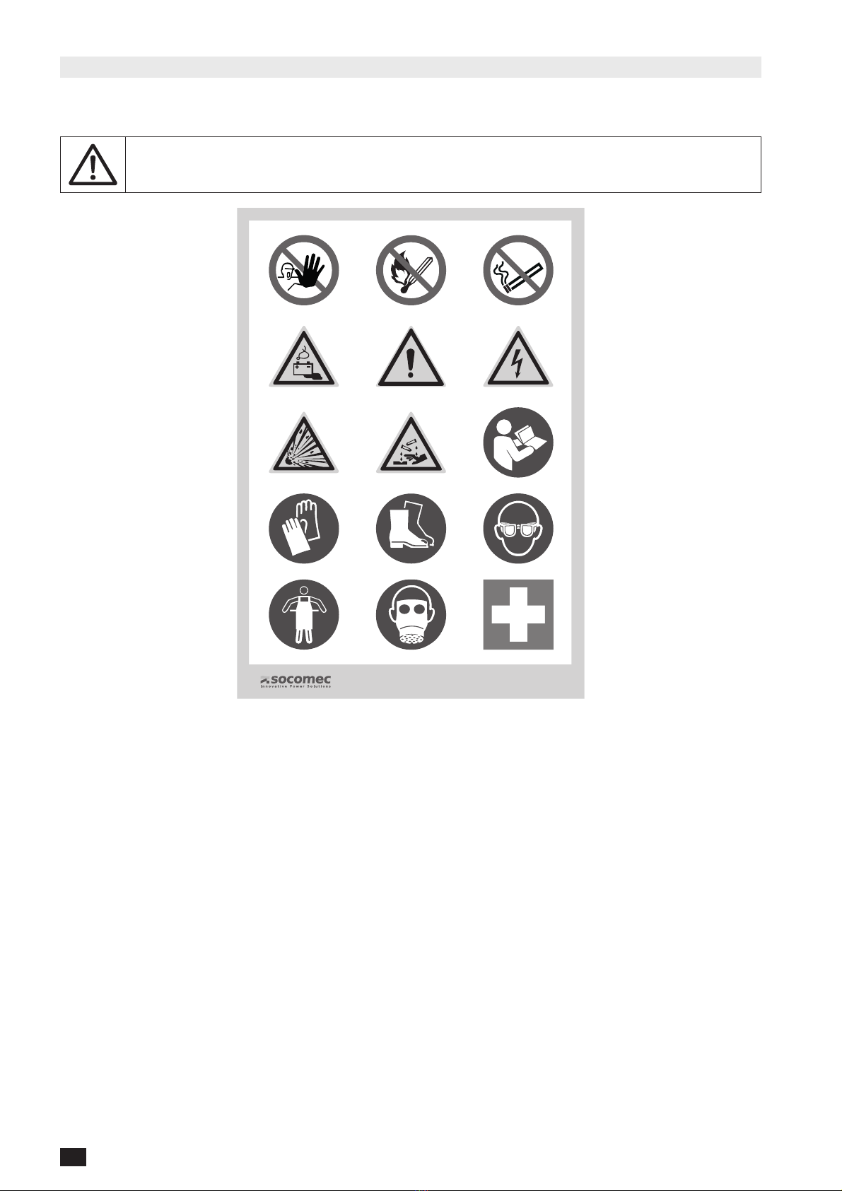
2.1 WARNING SYMBOLS . . . . . . . . . . . . . . . . . . . . . . . . . . . . . . . . . . . . . . . . . . . . . . . . . . . 8
3. ENVIRONMENTAL REQUIREMENTS AND HANDLING 10
3.1 ENVIRONMENTAL REQUIREMENTS. . . . . . . . . . . . . . . . . . . . . . . . . . . . . . . . . . . . . . . 10
3.2 SHIPPING AND MOVING. . . . . . . . . . . . . . . . . . . . . . . . . . . . . . . . . . . . . . . . . . . . . . . . 11
3.2.1 UNPACKING PROCEDURES . . . . . . . . . . . . . . . . . . . . . . . . . . . . . . . . . . . 11
4. ELECTRICAL INSTALLATION 12
5. OVERVIEW 13
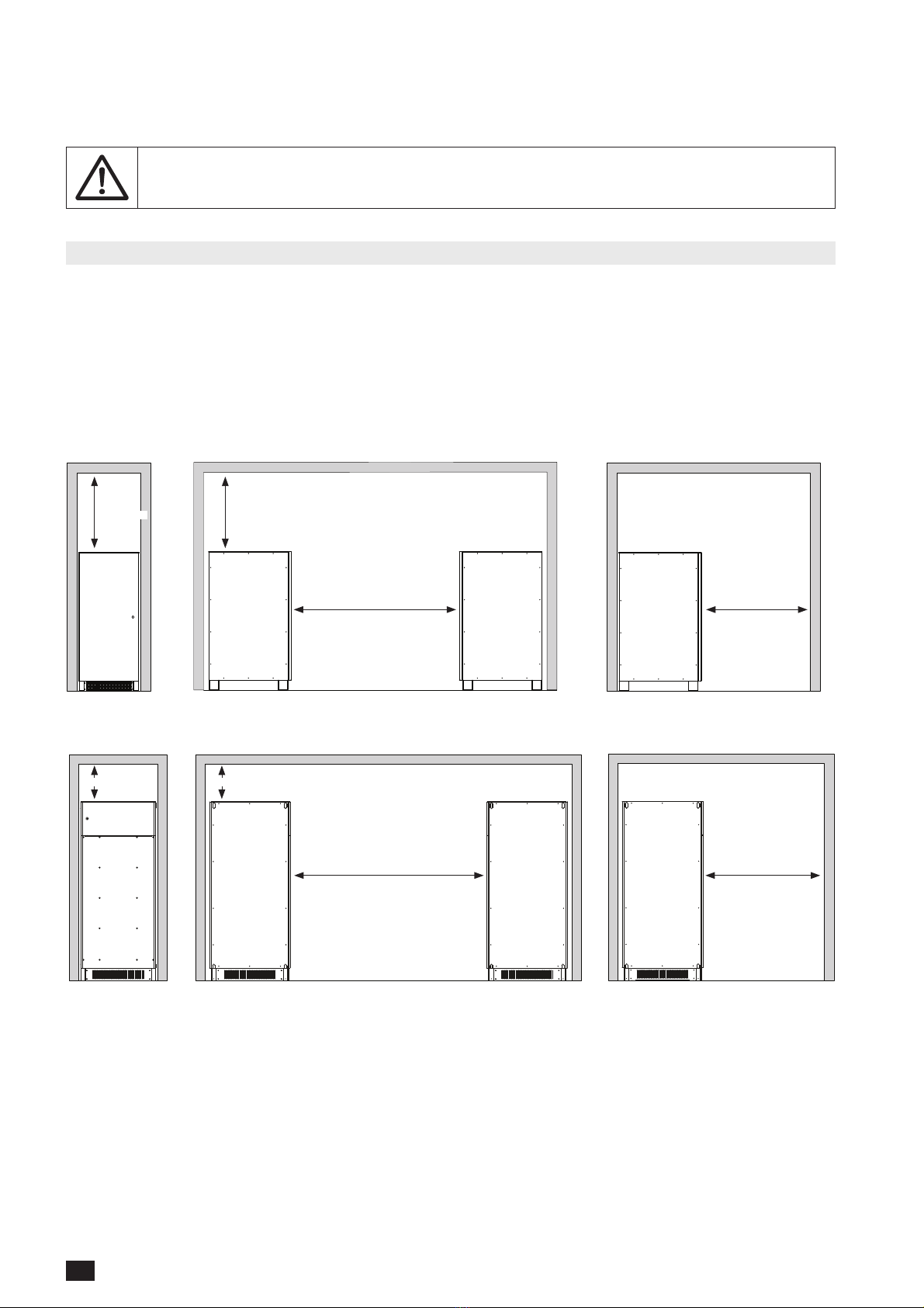
5.1 CORRECT PLACEMENT . . . . . . . . . . . . . . . . . . . . . . . . . . . . . . . . . . . . . . . . . . . . . . . . 14
6. CONNECTIONS - ITYPXXXXXXX2PXX 18
6.1 TWO CABLE DC CONNECTION . . . . . . . . . . . . . . . . . . . . . . . . . . . . . . . . . . . . . . . . . . 18
7. CONNECTIONS - 1MBFXXXXXXX4PXX 22
7.1 FOUR CABLE DC CONNECTION . . . . . . . . . . . . . . . . . . . . . . . . . . . . . . . . . . . . . . . . . 22
7.2 THREE CABLE DC CONNECTION . . . . . . . . . . . . . . . . . . . . . . . . . . . . . . . . . . . . . . . . 23
8. CONNECTIONS - 2 X 1MBFXXXXXXX4PXX 26
8.1 FOUR CABLE DC CONNECTION . . . . . . . . . . . . . . . . . . . . . . . . . . . . . . . . . . . . . . . . . 26
8.2 THREE CABLE DC CONNECTION . . . . . . . . . . . . . . . . . . . . . . . . . . . . . . . . . . . . . . . . 27
9. CONNECTIONS - 2 X 1MBFXXXXXXX2FXX 30
9.1 FOUR CABLE DC CONNECTION . . . . . . . . . . . . . . . . . . . . . . . . . . . . . . . . . . . . . . . . . 30
9.2 THREE CABLE DC CONNECTION . . . . . . . . . . . . . . . . . . . . . . . . . . . . . . . . . . . . . . . . 31
10. CONNECTIONS - 2 X 1MBFXXXXXXX2FXX 34
10.1 FOUR CABLE DC CONNECTION . . . . . . . . . . . . . . . . . . . . . . . . . . . . . . . . . . . . . . . . 34
10.2 THREE CABLE DC CONNECTION . . . . . . . . . . . . . . . . . . . . . . . . . . . . . . . . . . . . . . . 35
11. CONNECTIONS - 1MBFXXXXXXX4FXX 38
11.1 FOUR CABLE DC CONNECTION . . . . . . . . . . . . . . . . . . . . . . . . . . . . . . . . . . . . . . . . 38
11.2 THREE CABLE DC CONNECTION . . . . . . . . . . . . . . . . . . . . . . . . . . . . . . . . . . . . . . . 39
12. CONNECTIONS - 2 X 1MBFXXXXXXX4FXX 42
12.1 FOUR CABLE DC CONNECTION . . . . . . . . . . . . . . . . . . . . . . . . . . . . . . . . . . . . . . . . 42
12.2 THREE CABLE DC CONNECTION . . . . . . . . . . . . . . . . . . . . . . . . . . . . . . . . . . . . . . . 43
13. CONNECTIONS - 1MBFXXXXXXX2H-1 + 1MBFXXXXXXX20XX 46
13.1 FOUR CABLE DC CONNECTION . . . . . . . . . . . . . . . . . . . . . . . . . . . . . . . . . . . . . . . . 47
13.2 THREE CABLE DC CONNECTION . . . . . . . . . . . . . . . . . . . . . . . . . . . . . . . . . . . . . . . 48
14. CONNECTIONS - 1MBFXXXXXXX4HXX 54
14.1 FOUR CABLE DC CONNECTION . . . . . . . . . . . . . . . . . . . . . . . . . . . . . . . . . . . . . . . . 55
14.2 THREE CABLE DC CONNECTION . . . . . . . . . . . . . . . . . . . . . . . . . . . . . . . . . . . . . . . 56
15. CONNECTIONS - 1MBFXXXXXXX2HXX + 1MBFXXXXXXX20XX 62
15.1 FOUR CABLE DC CONNECTION . . . . . . . . . . . . . . . . . . . . . . . . . . . . . . . . . . . . . . . . 63
15.2 THREE CABLE DC CONNECTION . . . . . . . . . . . . . . . . . . . . . . . . . . . . . . . . . . . . . . . 64
16. CONNECTIONS - 1MBFXXXXXXX4MXX 70
16.1 THREE CABLE DC CONNECTION . . . . . . . . . . . . . . . . . . . . . . . . . . . . . . . . . . . . . . . 71
17. CONNECTIONS - 1MBFXXXXXXX2MXX + 1MBFXXXXXXX0MXX 76
17.1 THREE CABLE DC CONNECTION . . . . . . . . . . . . . . . . . . . . . . . . . . . . . . . . . . . . . . . 77
18. TEMPERATURE SENSOR 79
19. STANDARD FEATURES AND OPTIONS 80
19.1 TRIPPING SYSTEM . . . . . . . . . . . . . . . . . . . . . . . . . . . . . . . . . . . . . . . . . . . . . . . . . . . 80
19.2 IP31 . . . . . . . . . . . . . . . . . . . . . . . . . . . . . . . . . . . . . . . . . . . . . . . . . . . . . . . . . . . . . . . 80
19.3 IP32 . . . . . . . . . . . . . . . . . . . . . . . . . . . . . . . . . . . . . . . . . . . . . . . . . . . . . . . . . . . . . . . 81
19.4 BACK BASE . . . . . . . . . . . . . . . . . . . . . . . . . . . . . . . . . . . . . . . . . . . . . . . . . . . . . . . . . 81
19.5 2 LATERAL COVERS . . . . . . . . . . . . . . . . . . . . . . . . . . . . . . . . . . . . . . . . . . . . . . . . . . 82
19.6 SPILL CONTAINER . . . . . . . . . . . . . . . . . . . . . . . . . . . . . . . . . . . . . . . . . . . . . . . . . . . 82
20. SAFEGUARDING THE ENVIRONMENT 83
21. TECHNICAL SPECIFICATIONS 84
22. APPENDIX 85
22.1 PLAN 1: FLOOR FIXING. . . . . . . . . . . . . . . . . . . . . . . . . . . . . . . . . . . . . . . . . . . . . . . . 85
22.2 PLAN 2: DIMENSIONS. . . . . . . . . . . . . . . . . . . . . . . . . . . . . . . . . . . . . . . . . . . . . . . . . 86

4EN BATTERY CABINET ITYS PRO 10-20 kVA, MASTERYS 10-160 kVA- Ref.: IOMXXXABXX00-EN 01
1. CERTIFICATE AND CONDITIONS OF WARRANTY
The SOCOMEC battery cabinet is part of a UPS system.
For the warranty conditions, please refer to the relevant chapter of the UPS manual.

5EN
BATTERY CABINET ITYS PRO 10-20 kVA, MASTERYS 10-160 kVA - Ref.: IOMXXXABXX00-EN 01
2. SAFETY STANDARDS
NOTE: This user manual specifies installation and maintenance procedures, technical data and
safety instructions for SOCOMEC products. For further information visit the Socomec website:
www.socomec.com.
NOTE: Before carrying out any operations on the unit read the installation and operating manual
carefully. All safety instructions contained in this document must be read, understood and
followed. Keep this manual safe for future reference.
DANGER: Failure to observe safety standards could result in fatal accidents or serious injury, and
damage equipment or the environment.
NOTE: Any work carried out on the equipment must be performed by skilled, qualified techni-
cians who have attended SOCOMEC training courses on construction, installation and hazards,
and are experienced in procedures, practices and precautions to be taken.
DANGER: High electrical voltages are generated inside the power system, which is danger-
ous for maintenance personnel not suitably qualified or trained for such work. Keep unqualified
personnel away from batteries.
NOTE: This equipment complies with the European Community directives for industrial equip-
ment and bears the CE approval mark.
NOTE: Install the unit in accordance with clearance indications in order to prevent access to
handling devices and guarantee sufficient ventilation (refer to 'Environmental requirements'
chapter).
NOTE: Install the unit in a technical room with the following features:
• Suitable size.
• Clean.
• Adequately ventilated.
• Maintained at a temperature between 0 °C and 40 °C (15 to 25 °C recommended for longer battery
life).
• An even solid floor that can support the weight of the unit.
• Free from conductive, inflammable, explosive and corrosive items.
• Free from moisture, steam, mould, insects, vermin, dust, abrasive dust, corrosive gases, salty atmos-
phere or contaminated cooling refrigerant, harmful fumes, explosive dust/gas mixtures, restricted
ventilation (for UPS and/or battery), radiated or conducted heat from other sources.
• Pollution level < 2 in accordance with IEC 60664-1.
• Atmosphere which is not conductive, inflammable, explosive or corrosive atmosphere.
• Non-radioactive environment.
NOTE: Do not:
• Install the unit outdoors.
• Place the unit in a room with ongoing construction work.
• Insert foreign bodies in the unit.
• Expose the unit to rain or direct sunlight.
• Expose the unit to abnormal vibrations, shocks or tilt it.
CAUTION: If the unit is found to be damaged externally or internally, or any of the accessories
are damaged or missing, contact SOCOMEC. Do not operate the unit if it has suffered a violent
mechanical shock of any kind.
NOTE: When the equipment is transferred from a cold to a warm place wait approx. two hours
before activating the unit.
CAUTION: Do not open or damage batteries. Released electrolyte is harmful to the skin and eyes
and may be toxic.
CAUTION: Do not dispose of batteries in a fire as they may explode.

6EN BATTERY CABINET ITYS PRO 10-20 kVA, MASTERYS 10-160 kVA- Ref.: IOMXXXABXX00-EN 01
WARNING: Do not wear clothes and footwear which may build up electrostatic charge. Only use
an absorbent cloth dampened with water to clean the battery. Other cleaning agents may result
in the build-up of static charge or damage the battery cases.
NOTE: Use Personal Protective Equipment (PPE) when carrying out any work on the unit.
NOTE: When carrying out electrical installation, all applicable standards specified by the IEC (in
particular IEC 60364) and the electricity supplier must be observed. All national standards appli-
cable to batteries must be observed. For further information refer to 'Technical specifications'
chapter.
NOTE: Only use accessories recommended or sold by the manufacturer.
NOTE: Batteries must only be replaced with batteries recommended or sold by the manufacturer.
Batteries must only be replaced by qualified technicians.
NOTE: Before connecting the unit check it is fully compatible with the UPS model.
NOTE: If using cabinets not supplied by the manufacturers of the UPS, it is the installer’s respon-
sibility to check the electrical compatibility and the presence of appropriate protection devices
between the UPS and the battery cabinet (fuses and switches of sufficient capacity to protect
the cables from the UPS to the battery cabinet). As soon as the UPS is switched on (before clos-
ing the battery switches) the battery parameters must be verified accordingly (voltage, capacity,
number of elements, etc.) on the mimic panel menu. If the values indicated on the battery cabinet
data plate are different from those shown on the mimic panel, please correct the settings.
NOTE: Use the double insulated cables supplied with the unit to connect the UPS to the battery
cabinet.
CAUTION: A battery can present a risk of electrical shock and high short circuit current. The
following precautions should be observed when working on batteries:
• Remove watches, rings or other metal objects
• Use tools with insulated handles
• Wear rubber gloves and boots
• Do not lay tools or metal parts on top of batteries
• Disconnect the charging source prior to connecting or disconnecting battery terminals
• Determine if battery is inadvertently earthed. If inadvertently grounded, remove source from ground.
Contact with any part of a grounded battery can result in electrical shock. The likelihood of such
shock can be reduced if such grounds are removed during installation and maintenance (applicable to
equipment and remote battery supplies without a grounded supply circuit).
WARNING: Batteries must not be connected or disconnected when current is flowing. Isolate the
circuit elsewhere first.
WARNING: Before carrying out any operations, ensure that:
• The switches located inside the battery cabinet are open
• The UPS is not live and all mains or battery switches are open
• The switches upstream of the UPS are open
• Wait approx. 5 minutes for the unit to discharge completely.
NOTE: Connect the PE ground conductor before making any other connections.
DANGER! RISK OF ELECTRIC SHOCK: Disconnect all power sources before carrying out any
operations on the unit (cleaning and maintenance, connection of appliances, etc.).
DANGER! RISK OF ELECTRIC SHOCK: After disconnecting all power sources wait approx. 5
minutes for the the unit to discharge completely.

7EN
BATTERY CABINET ITYS PRO 10-20 kVA, MASTERYS 10-160 kVA - Ref.: IOMXXXABXX00-EN 01
DANGER! RISK OF ELECTRIC SHOCK: Do not interfere with the disconnection switches on the
unit while the UPS is running on battery power.
DANGER! RISK OF ELECTRIC SHOCK: There is no insulation between the batteries and the
mains supply therefore it is extremely dangerous to touch any parts of the accumulator battery.
WARNING: Strictly observe the following:
• Polarity of each individual string: cabling errors with inversion of battery polarity may cause permanent
damage to the equipment
• Cable cross-section (refer to 'Connections' chapter).
NOTE: As soon as the UPS is switched on (before closing the battery switches) the battery
parameters must be verified accordingly (voltage, capacity, number of elements, etc.) on the
mimic panel menu. If the values indicated on the battery cabinet data plate are different from
those shown on the mimic panel, please correct the settings.
NOTE: If the unit needs to be disposed of it must be given to companies specialising in the
disposal of the system’s constituent materials.
NOTE: The batteries are toxic waste. If the battery cabinet needs to be scrapped it is essential to
entrust the equipment solely and exclusively to firms specialising in the disposal of the materials
making up the system. These are obliged to break up and dispose of the various components in
accordance with the legal provisions in force in the country where the system is installed.
NOTE: Any use other than the specified purpose will be considered improper. The manufacturer/
supplier shall not be held responsible for any resulting damage. Risk and responsibility lies with
the system manager.
WARNING: the unit must be moved by two people at least, standing at the sides of the unit with
respect to the direction of movement.
WARNING! HEAVY WEIGHT: move the unit using suitable equipment, taking the utmost caution
at all times.
WARNING: when moving the unit on even slightly sloping surfaces, use the clamping equipment
and breaking devices to ensure that the unit does not fall over.
NOTE: do not move the unit by putting pressure on the front door.

8EN BATTERY CABINET ITYS PRO 10-20 kVA, MASTERYS 10-160 kVA- Ref.: IOMXXXABXX00-EN 01
2.1 WARNING SYMBOLS
Warning symbols are provided to identify the battery room and provide information about possible hazards.
Signs should be placed outside the battery room in a visible position.
The installer is responsible for ensuring that the installation of the battery cabinets and their
operating environment conform to national and international codes and safety standards.
www.socomec.com

9EN
BATTERY CABINET ITYS PRO 10-20 kVA, MASTERYS 10-160 kVA - Ref.: IOMXXXABXX00-EN 01
Symbols Description
Protective earth terminal (PE).
Authorised personnel only.
Only qualified personnel are permitted to work on the batteries.
Do not use naked flames or cause sparks in the vicinity of the accumulators.
No smoking.
Batteries charging!
Batteries and related parts contain lead which is dangerous to health if ingested. Wash hands
after handling!
Accumulators are heavy!
Use suitable transport and lifting equipment to work safely.
Risk of electric shock!
Connecting accumulators in series creates hazardous voltages.
Risk of explosion! Avoid short circuits!
Never place tools or metal objects on the accumulators.
Corrosive liquids (electrolyte).
Read the user instructions carefully.
Read the user manual before performing any operations.
Wear protective gloves
Wear safety shoes.
Wear protective goggles.
In the event of accidents, improper use, failure or electrolyte leakage wear a protective apron.
In the event of accidents, improper use, failure or electrolyte leakage wear a gas mask.
In the event of contact with the eyes, wash immediately with plenty of water and call a doctor.
Call a doctor immediately in the event of accidents or illness.
Do not dispose of in normal waste stream (symbol waste electrical and electronic equipment).

10 EN BATTERY CABINET ITYS PRO 10-20 kVA, MASTERYS 10-160 kVA- Ref.: IOMXXXABXX00-EN 01
3. ENVIRONMENTAL REQUIREMENTS AND HANDLING
The packaging guarantees the stability of the battery cabinet during shipping and physical transfer. Carry the pack-
aged unit as close as possible to the installation site.
When moving the unit on even slightly sloping surfaces, use the locking equipment and braking
devices to ensure that the unit does not fall over.
3.1 ENVIRONMENTAL REQUIREMENTS
• The unit is not designed for outdoor use.
• Do not expose the battery cabinet to direct sunlight or sources of excessive heat.
• Do not put any object on top of the unit.
• The recommended operating temperature, humidity and altitude values are listed in the technical specifications
table (see Technical Specifications). Cooling systems may be required to maintain these values.
• The unit must be installed in an environment with no obstructions and which is dry, clean and dust-free.
• Avoid dusty environments or areas where there is dust from conductive or corrosive materials (e.g. metal dust or
chemical solutions).
≥80 cm
≥80 cm
≥80 cm
≥80 cm
≥170 cm
≥170 cm
≥110 cm
≥110 cm
between the doors
between the doors
from the wall
from the wall
1
1
≥2 cm
≥2 cm
≥5 cm
≥5 cm
≥5 cm
≥5 cm
≥5 cm
≥5 cm
≥2 cm
≥2 cm
FRONT VIEW
FRONT VIEW
SIDE VIEW
SIDE VIEW
SIDE VIEW
SIDE VIEW
≥40 cm
≥40 cm
≥40 cm
≥40 cm
≥210 cm
≥210 cm
≥130 cm
≥130 cm
between the doors
between the doors
from the wall
from the wall
1
1
≥2 cm
≥2 cm
≥5 cm
≥5 cm
≥5 cm
≥5 cm
≥5 cm
≥5 cm
≥2 cm
≥2 cm
FRONT VIEW
FRONT VIEW
SIDE VIEW
SIDE VIEW
SIDE VIEW
SIDE VIEW
1. In accordance with standard IEC 60364.

11EN
BATTERY CABINET ITYS PRO 10-20 kVA, MASTERYS 10-160 kVA - Ref.: IOMXXXABXX00-EN 01
3.2 SHIPPING AND MOVING
The unit must remain in a vertical position during all shipping and moving operations.
Ensure that the floor is strong enough to support the weight of the unit.
WARNING! HEAVY WEIGHT!
Move the battery cabinet using a fork lift truck, taking the utmost caution at all times.
NOTE: the unit MUST be handled carefully by at least two people.
Avoid moving the unit by putting pressure on the front door.
CAUTION IF DAMAGED: if packaging is crushed, ripped or open such that the inner contents are
revealed, the equipment should be kept in an isolated area and inspected by a qualified person.
If the packaging cannot be shipped the contents should be collected promptly, kept apart, and
the sender or recipient should be contacted.
All packaging must be recycled in compliance with existing legislation in the country where the
system is installed.
3.2.1 UNPACKING PROCEDURES
Cables
5x12
2x25mm24x16mm21x35mm2+
1x35mm2
1x70mm2 +
1x70mm2
1x95mm2 +
1x95mm2 +
1x50mm2
1x95mm2 +
1x95mm2
ITYPxxxxxxx2Pxx x1-----x4 x1 -
1MBFxxxxxxx4Pxx -x1----x4 x1 -
1MBFxxxxxxx2Fxx -x1----x4 x1 -
1MBFxxxxxxx4Fxx -x2----x4 x1 -
1MBFxxxxxxx2H-1 --x2---- - x1
1MBFxxxxxxx20xx ---x1--- - x1
1MBFxxxxxxx4Hxx ---x2--- - x1
1MBFxxxxxxx2Hxx ---x2--- - x1
1MBFxxxxxxx4Mxx ----x1-- - x1
1MBFxxxxxxx2Mxx ----x1-- - x1
1MBFxxxxxxx0Mxx -----x1- - x1

12 EN BATTERY CABINET ITYS PRO 10-20 kVA, MASTERYS 10-160 kVA- Ref.: IOMXXXABXX00-EN 01
4. ELECTRICAL INSTALLATION
NOTE!
Before carrying out any operations on the unit read the 'Safety standards' chapter carefully.
WARNING!
Before carrying out any operations, ensure that:
• The switch located inside the battery cabinet is open;
• The UPS is not live and all mains or battery switches are open;
• The switches upstream of the UPS are open.
Use the cables supplied with the unit to connect the UPS to the Battery cabinet.
Cabling errors with inversion of battery polarity may cause permanent damage to the equipment.
If using cabinets not supplied by the UPS manufacturer, it is the installer’s responsibility to check
electrical compatibility and the presence of appropriate protection devices between the UPS and
the battery cabinet (fuses and switches of sufficient capacity to protect the cables from the UPS
to the battery cabinet). As soon as the UPS is switched on (before closing the battery switches)
the battery parameters must be verified accordingly (voltage, capacity, number of elements, etc.)
on the mimic panel menu. If the values indicated on the battery cabinet data plate are different
from those shown on the mimic panel, please correct the settings.
IMPORTANT!
Protective earthing conductor (PE) must have sufficient current-carrying capacity. The PE cable
core size has to be chosen according to the PROTECTIVE CURRENT RATING of the earth circuit
which depends on the provision and location of overcurrent protective devices. We suggest
35mm² for Masterys Battery Cabinet.

13EN
BATTERY CABINET ITYS PRO 10-20 kVA, MASTERYS 10-160 kVA - Ref.: IOMXXXABXX00-EN 01
5. OVERVIEW
UPS type
Battery protection
Kit / Options / Versions
xxxxxxxxxxxxxxx
—
—
—
—
—
—
—
—
I T Y P Battery cabinet for Itys Pro 2 P
—
—
Fuse holder + 2 fuses
1 M B F Battery cabinet for Masterys 4 P
—
—
Fuse holder + 4 fuses
2F
—
—
Switch-disconnector + 2 fuse
4F
—
—
Switch-disconnector + 4 fuse
2H- 1
Magnetothermal switch 4 pole
250A
20
—
—
Without protection
4H
—
—
Magnetothermal switch 4 pole
250A
2H
—
—
Magnetothermal switch 4 pole
250A
4M
—
—
Magnetothermal switch 4 pole
400A
2M
—
—
Magnetothermal switch 4 pole
400A
0M
—
—
Without protection
xxxxxxxxxxxxxxx

14 EN BATTERY CABINET ITYS PRO 10-20 kVA, MASTERYS 10-160 kVA- Ref.: IOMXXXABXX00-EN 01
5.1 CORRECT PLACEMENT
1 BATTERY CABINET 2 BATTERY CABINETS
ITYS PRO 10-20 kVA
ITYPxxxxxxx2Pxx
1
UPS
MASTERYS 10-40 kVA
1MBFxxxxxxx4Pxx
2
1MBFxxxxxxx4Pxx + 1MBFxxxxxxx4Pxx
3
UPS UPS
MASTERYS 10-80 kVA
1MBFxxxxxxx2Fxx + 1MBFxxxxxxx2Fxx
4
UPS
1MBFxxxxxxx4Fxx
5
1MBFxxxxxxx4Fxx + 1MBFxxxxxxx4Fxx
6
UPS UPS
1MBFxxxxxxx2H-1 + 1MBFxxxxxxx20xx
7
UPS

15EN
BATTERY CABINET ITYS PRO 10-20 kVA, MASTERYS 10-160 kVA - Ref.: IOMXXXABXX00-EN 01
1 BATTERY CABINET 2 BATTERY CABINETS
MASTERYS 100-120 kVA
1MBFxxxxxxx4Hxx
8
1MBFxxxxxxx2Hxx + 1MBFxxxxxxx20xx
9
UPS UPS
MASTERYS 160 kVA
1MBFxxxxxxx4Mxx
10
1MBFxxxxxxx2Mxx + 1MBFxxxxxxx0Mxx
11
UPS UPS


ITYPxxxxxxx2Pxx
ITYS PRO 10-20kVA
1234567891011
www.socomec.com

18 EN BATTERY CABINET ITYS PRO 10-20 kVA, MASTERYS 10-160 kVA- Ref.: IOMXXXABXX00-EN 01
6. CONNECTIONS - ITYPXXXXXXX2PXX
NOTE!
Before carrying out any operations on the unit read the 'Safety standards' chapter carefully.
6.1 TWO CABLE DC CONNECTION
A cable
1
2
+B -B+B+B -B
LOCKING CABLE CLAMP
CABLE CABLE
LENGTH COLOUR CABLE
SECTION
UPS ITYPxxxxxxx2Pxx
+B +B [Ø M10, 40Nm] A 3500 mm BROWN 1 x 25 mm²
-B -B [Ø M10, 40Nm] BLUE 1 x 25 mm²


This manual suits for next models
1
Table of contents
Other socomec Power Distribution Unit manuals
Popular Power Distribution Unit manuals by other brands

Tripp Lite
Tripp Lite SmartOnline SUPDMB20KHW owner's manual

Cisco
Cisco Surge-Gap Multimedia Tap Installation and operation guide

Novatek
Novatek UBZ-304 operating manual

ETA Systems
ETA Systems PD8L Owners manual and operation instructions

PortaCo
PortaCo D-60S09-F7-S Operation, maintenance, and repair manual

Art
Art PB 4X4 Specification sheet