SODECA VSD/A Instruction sheet

Code: 1127947
Doc. Num: 0000003909 (2016-05-06)
VSD/A
ES
EN
Wiring and Configuration Manual
Convertidor de Frecuencia
Variable Frequency Drive
Conversor de frequência
IP20 & IP66 (NEMA 4X)
0.37 – 22Kw (0.5 – 30HP)
110 – 480V
www.sodeca.com
PT
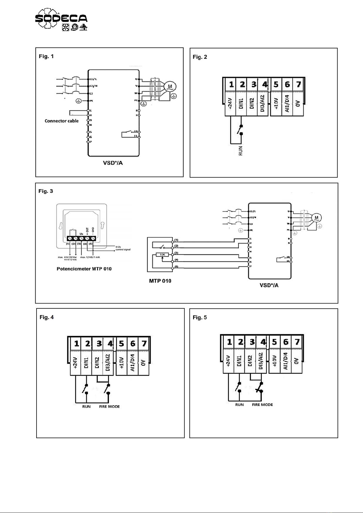

Fig. 6
Fig. 9
VSD/A
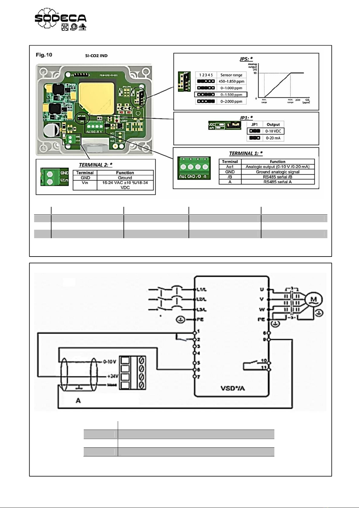
Fig. 11
A
ES
Transmisor de presión diferencial SI-PRESIÓN TPDA
EN
Differential pressure transmitter SI-PRESIÓN TPDA
PT
Transmissor de pressão diferencial SI-PRESIÓN TPDA
JP5
JP1
TERMINAL 1
TERMINAL 2
ES
Escala de medida sonda
Tipo de salida analógica
Salida analógica y bus
Alimentación sonda
EN
Measuring probe scale
Analog output type
Analog output and bus
Power supply probe
PT
Escala de medida da sonda
Tipo de saída analógica
Saída analógica e bus
Alimentação da sonda
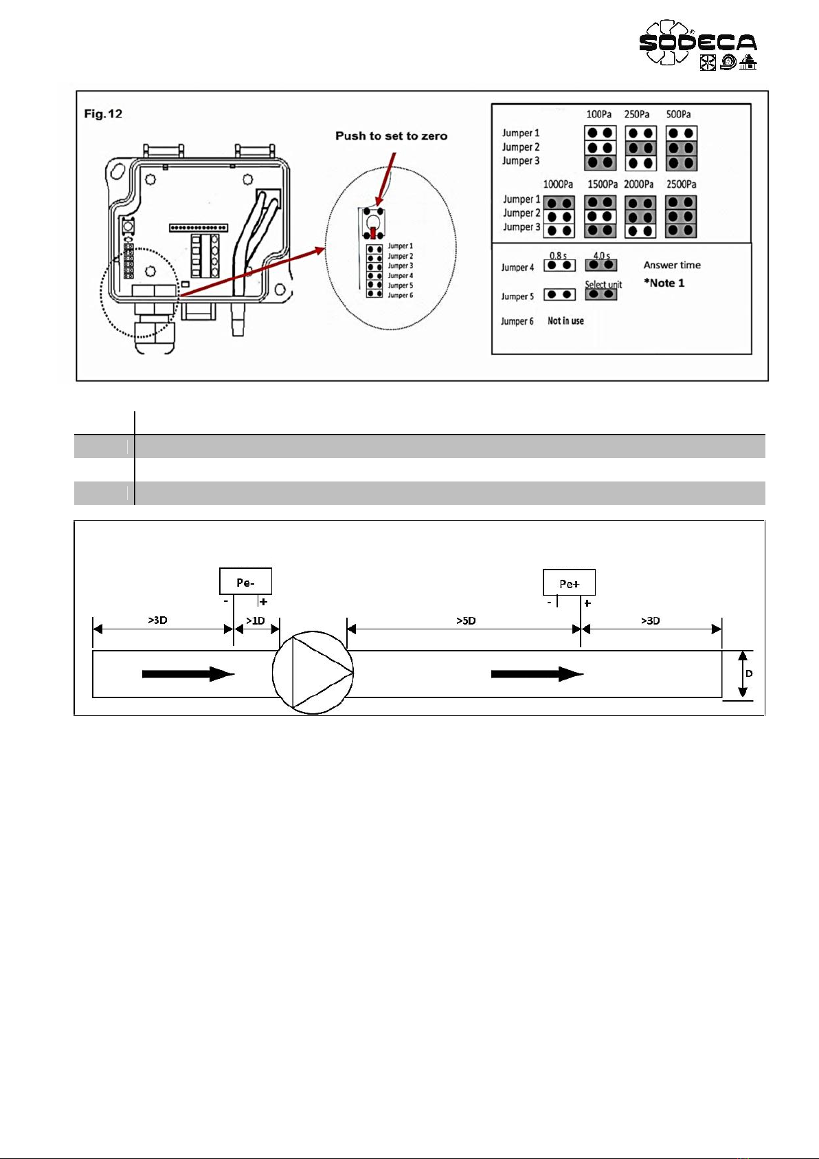
Fig. 13
*Note 1
ES
Las unidades de medida pueden cambiarse solo con el jumper 5 instalado. Elimine el jumper al terminar
EN
The measurement units can be changed only with the jumper 5 installed. Remove the jumper at the end.
PT
As unidades de medida apenas podem ser alteradas com o jumper 5 instalado. Elimine o jumper ao terminar
Outlet
Inlet

1
EN
INDEX
WARNINGS 2
INTRODUCTION TO COMMON OPERATIONS WITH THE VSD*/A 2
AP1. BASIC CONFIGURATION – Drive control using the keypad – VSD1-D, VSD3-D 3
1.1 PROGRAMMING 3
1.2 WIRING 3
1.3 “BASIC CONFIGURATION” OPERATION MODE 3
AP2. EXTERNAL KIT MODE – Manipulate with the mtp 010 remote control 4
2.1 PROGRAMMING 4
2.2 WIRING 4
2.3 “EXTERNAL REMOTE CONTROL KIT” OPERATION MODE 4
AP3. MIXED MODE – External start, speed adjustment with the internal keypad. 5
3.1 PROGRAMMING 5
3.2 WIRING 5
3.3 “MIXED” OPERATION MODE 5
AP4. FIRE MODE WITH NO OR NC ACTIVATION SIGNAL – Preset speeds 6
4.1 PROGRAMMING 6
4.2 WIRING 7
4.3 “FIRE MODE with Preset Speeds” OPERATION MODE 7
AP5. FIRE MODE WITH NC ACTIVATION SIGNAL – Analog speed/potentiometer 8
5.1 PROGRAMMING 8
5.2 WIRING 8
5.3 “FIRE MODE with Analog Speed” OPERATION MODE 8
AP6. FIRE MODE + CO WITH NO OR NC ACTIVATION SIGNAL – Preset speeds 9
6.1 PROGRAMMING 9
6.2 WIRING 10
6.3 “FIRE MODE + CO with preset speeds” OPERATION MODE 10
AP7. CO2 MODE 11
7.1 PROGRAMMING 11
7.2 SETPOINT ADJUSMENT OF THE CO2 CONCENTRATION 12
7.3 WIRING 12
7.4 PROBE SI-CO2 IND CONFIGURATION 12
7.5 “CO2” OPERATION MODE 12
AP8. TEMPERATURE MODE 13
8.1 PROGRAMMING 13
8.2 PROBE SI-TEMP IND CONFIGURATION 13
8.3 SETPOINT ADJUSMENT OF THE CO2 CONCENTRATION 14
8.4 WIRING 14
8.5 “TEMPERATURE” OPERATION MODE 14
AP9. PRESSURE CONTROL MODE – VSD1-P, VSD3-P 15
9.1 PROGRAMMING 15
9.2 PRESSURE SETPOINT ADJUSTMENT 15
9.3 WIRING 16
9.4 PROBE SI-PRESSURE TPDA CONFIGURATION 16
9.5 “PRESSURE CONTROL” OPERATION MODE 16

2
EN
WARNINGS
The AC Variable Speed Drives (VSD*/A) supplied by SODECA are meant to be handled using the keypad, see “BASIC
CONFIGURATION” section. Other control ways are possible with simple and quick adjustments. Some of them are
explained in this guide. This guide is a summary from the complete VSD*/A guidebook and is meant to help with the
equipment’s installation and start-up of its most common operations. If the user’s needs aren’t properly fitted with any of the
operation modes found in this guide check the Installation and Operation Manual of the VSD/A (download it on
sodeca.com), or contact with our technic support SODECA.
It is recommended to read all the security information and obligations/recommendations that are instructed in the VSD*/A
User Guide. This is an instructive guide about the applications and does not replace the complete guide, it’s an addition. It
is the user responsibility to apply all the required measures needed for the correct installation and programming of the
VSD*/A as instructed in the user guide.
INTRODUCTION TO COMMON OPERATIONS WITH THE VSD*/A
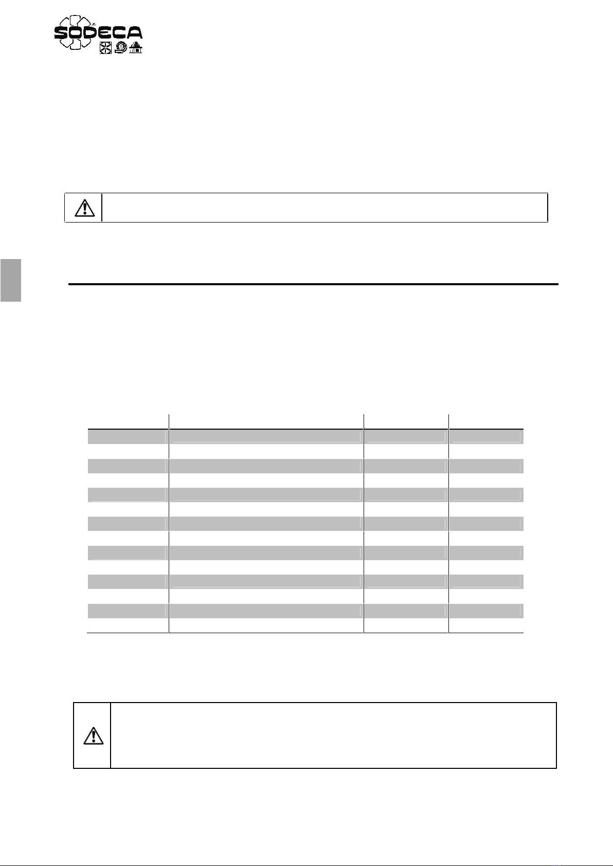
The family of the AC Variable Speed Drive (from now on, “Drive”) is well-known for its easy and quick configuration, as
shown in the table below. Before the start of the programming or the start up, it is important to read carefully this page and
learn the four most common actions that the user may use during the adjustment process and start up.
In the next section it’s explained with detail the most common applications in a concise and practical way, which will make
the start up last only a few a minutes.
3
EN
AP1. BASIC CONFIGURATION – Drive control using the keypad – VSD1-D, VSD3-D
The AC Variable Speed drives (VSD*/A) supplied by SODECA are meant to be handled using the keypad.
This section explains how to configure the “BASIC CONFIGURATION” control mode. This basic control mode allows
to start and stop the drive using its keypad, START y STOP keys, and change the rotation speed of the motor
with the y keys, without using the exterior control KIT.
1.1 PROGRAMMING
Use the next table to change to the basic configuration mode.
Table “BASIC CONFIRGURATION”
1.2 WIRING
Before the start of the programming, wire the L1-L2-L3 input phases when using three phase equipment and wire the
L1-L2/N input phases when using single phase equipment.
Once the “BASIC CONFIGURATION” control mode is selected, that is after introducing the parameters of the basic
configuration table (section 1.1), use a copper wire to short-circuit the terminals 1 and 2 of the VSD*/A. This short-circuit
enables the keypad control mode (See Fig. 1). This short-circuit can be changed with an external signal which would
prevent enabling the drive when the bridge between terminal 1 & 2 is open.
1.3 “BASIC CONFIGURATION” OPERATION MODE
1. Ensure the bridge between terminals 1 & 2 is closed. The display will show
2. Press the START key. The display will show and the drive will increase the speed until it reaches the
minimum speed programmed in the parameter.
3. Press to increase speed.
4. The drive will increase gradually, with the acceleration ramp previously programmed, until the key is no longer
pressed. The acceleration ramp is adjusted in theparameter, check before the start.
5. Press to decrease speed. The drive will decrease speed until the key is no longer pressed.
The acceleration ramp is adjusted in the parameter.
6. Press the STOP key. The drive will decrease its speed and stop. The acceleration ramp is adjusted in the
parameter.
7. The display will show . The drive is disabled.
8. In order to program the speed without pressing start, that is when the display is showing , press the STOP
key while the drive is disabled and the display will show the objective speed. Use the y keys to adjust the
wanted speed value. Press the STOP key to show on the display again.
9. Press START, the drive will accelerate towards the objective speed.
10. While the drive is enabled, we can visualize the consumption of the motor by pressing the navigator key >2
seconds.
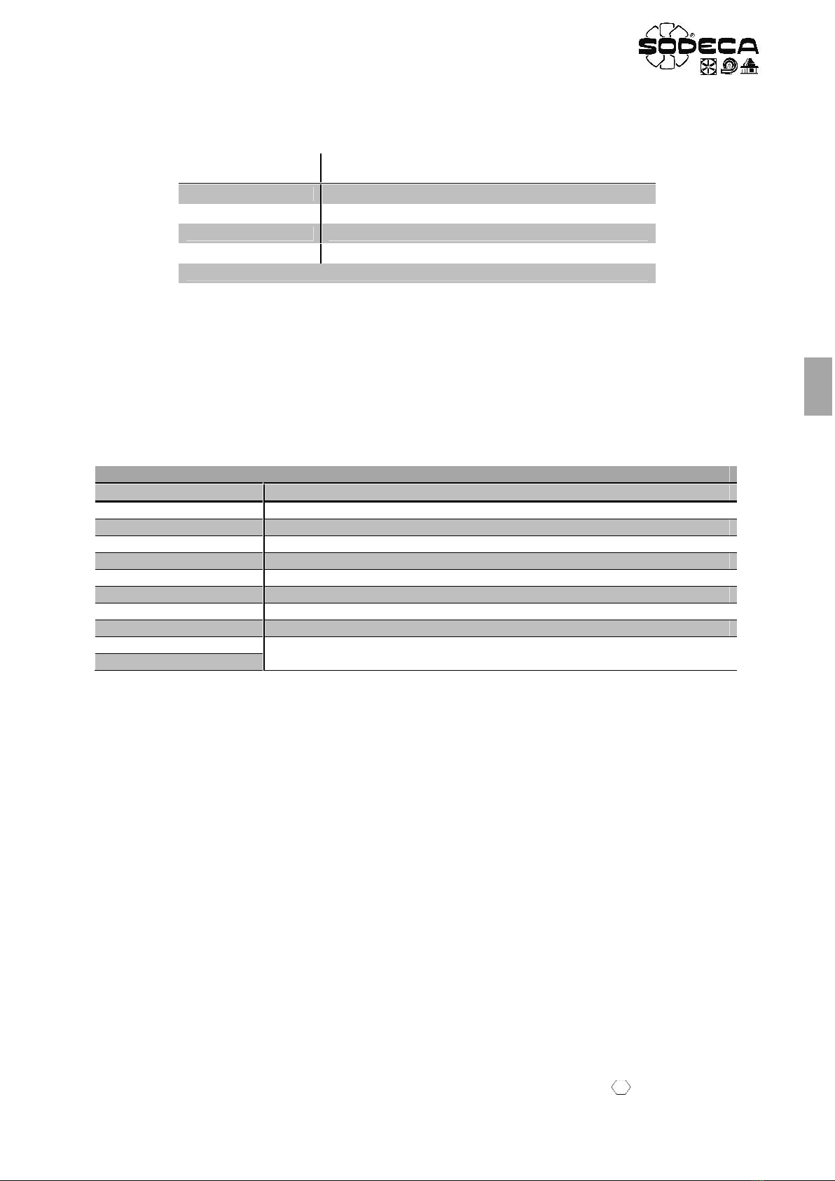
Parameter
Description
Adjustment
Units
Maximum Frequency
50.0
Hz
Minimum Frequency
20.0
Hz
Acceleration Ramp Time
20
s
Deceleration Ramp Time
20
s
Motor Rated Current
x.x
A
Primary Command Source
1
4
EN
AP2. EXTERNAL KIT MODE – Manipulate with the MTP 010 remote control
This section explains how to proceed with the configuration of the “EXTERNAL REMOTE CONTROL KIT –
MTP010”control mode. This simple control mode allows to start the drive and adjust the speed from the exterior remote
control kit MTP010.
2.1 PROGRAMMING
Use the next table to change the mode to the external kit mode.
Table “EXTERNAL REMOTE CONTROL KIT”
2.2 WIRING
Before the start of the programming, wire the L1-L2-L3 input phases when using three phase equipment and wire the
L1-L2/N input phases when using single phase equipment.
Once the “EXTERNAL REMOTE CONTROL KIT” control mode is selected, that is after introducing the parameters of
the external remote control kit table (section 2.1), wire the remote control as seen in the picture. (See Fig. 3).
2.3 “EXTERNAL REMOTE CONTROL KIT” OPERATION MODE
1. To start the drive, close the built-in switch of the remote control (starting switch ON). The display will stop showing
and the drive will accelerate towards the speed adjusted by the potentiometer. If the potentiometer is in the
lower speed position, the drive will stay at minimum velocity, programmed in the P-02 parameter.
2. The speed can be increased or decreased with the potentiometer.
3. The drive will increase gradually, with the acceleration ramp programmed in P-03. Check before the start.
4. The drive will decrease gradually, with the deceleration ramp programmed in P-04. Check before the start.
5. When the starting switch is OFF, the drive will start to decelerate and stop, showing in the display. The drive
is disabled
6. While the drive is enabled, we can visualize the consumption of the motor by pressing the navigator key >2
seconds.
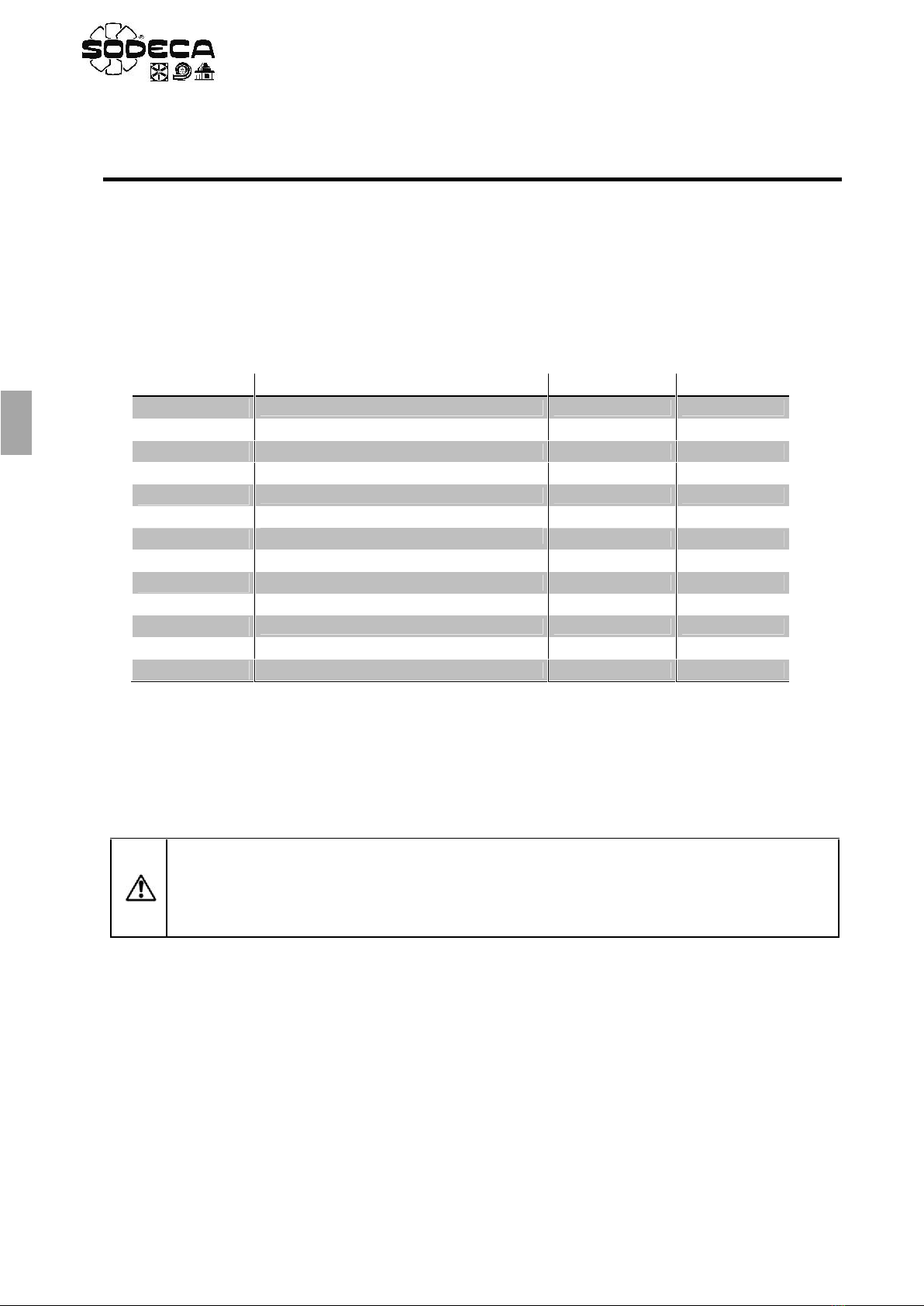
Parameter
Description
Adjustment
Units
Maximum Frequency
50.0
Hz
Minimum Frequency
20.0
Hz
Acceleration Ramp Time
20
s
Deceleration Ramp Time
20
s
Motor Rated Current
x.x
A
Primary Command Source
0
ATTENTION: If there’s a loss of the power supply while the ventilator is working with the starting
switch closed, the drive will be disabled with the display showing . Once the power supply
is restored, the drive will be disabled even with the starting switch ON. In order to start the drive
again, the switch must be changed to the OFF position and then changed again to the ON
position. See parameter to modify the configuration and change it to .
5
EN
AP3. MIXED MODE – External start, speed adjustment with the internal keypad.
This section explains how to configure the mixed control mode. This mode is a combination between the basic
configuration and the exterior remote control kit configuration. This mode allows to start the drive from an exterior switch
and adjust the speed with the internal keypad.
3.1 PROGRAMMING
Use the next table to change to the mixed mode.
Table “MIXED MODE”
3.2 WIRING
Before the start of the programming, wire the L1-L2-L3 input phases when using three phase equipment and wire the
L1-L2/N input phases when using single phase equipment.
Once the “MIXED” control mode is selected, that is after introducing the parameters of the mixed mode table (section
3.1), wire the remote control as seen in the picture. (See Fig. 2).
3.3 “MIXED” OPERATION MODE
1. To start the drive, close the built-in switch of the remote control (starting switch ON). The display will stop showing
and the drive will accelerate towards the minimum speed adjusted in the P-02 parameter.
2. Press to increase speed.
3. The drive will increase gradually, with the acceleration ramp previously programmed, until the key is no longer
pressed. The acceleration ramp is adjusted in theparameter, check before the start.
4. Press to decrease speed. The drive will decelerate until the key is no longer pressed.
The acceleration ramp is adjusted in the parameter.
5. When the starting switch is OFF, the drive will start to decelerate and stop, showing in the display. The drive
is disabled.
6. While the drive is enabled, we can visualize the consumption of the motor by pressing the navigator key >2
seconds.
Parameter
Description
Adjustment
Units
Maximum Frequency
50.0
Hz
Minimum Frequency
20.0
Hz
Acceleration Ramp Time
20
s
Deceleration Ramp Time
20
s
Motor Rated Current
x.x
A
Primary Command Source
1
Extended Menu Access code
101
Keypad Start Mode Select
3
ATTENTION: If there’s a loss of the power supply while the ventilator is working with the starting
switch closed, the drive will be disabled with the display showing . Once the power supply
is restored, the drive will be disabled even with the starting switch ON. In order to start the drive
again, the switch must be changed to the OFF position and then changed again to the ON
position. See parameter to modify the configuration and change it to .

6
EN
FIRE MODE
The Fire Mode function is designed to ensure continuous operation of the drive when an external alarm signal is activated
(fire alarm) until the drive is no longer capable of sustaining operation. This input may be linked to a fire control system
to allow maintained operation in emergency conditions, e.g. to clear smoke or maintain air quality within that building.
Fire Mode disables some protection features in the drive (Heat-sink Over-Temperature, 4-20mA fault, Faulty Thermistor
on Heat-sink…).
AP4. FIRE MODE with NO or NC activation signal– Preset speeds
This section explains how to configure the “FIRE”control mode with a normally open (NO) or a normally closed (NC)
activation signal and two operation speeds; the normal speed and the fire speed which can be adjusted as a preset
speed.
FIRE MODE with NO activation signal
When the free potential contact is open, which enables the Fire Mode, and the drive is receiving the RUN signal, the
drive will work at a preset speed with all the protections enabled. If the fire mode signal is active, that is when the
activation contact changes to closed position, and the drive is receiving the start signal (it can be the a contact of the fire
mode), the drive will work at a preset speed with all the protections disabled. (See Fig.4.)
MODO FUEGO with NC activation signal
When the free potential contact is closed, which enables the Fire Mode, and the drive is receiving the RUN signal, the
drive will work at a preset speed with all the protections enabled. If the fire mode signal is active, that is when the
activation contact changes to open position, and the drive is receiving the start signal (it can be a contact of the fire
mode), the drive will work at a preset speed with all the protections disabled. (See Fig.5.)
4.1 PROGRAMMING
Use the next table to change to, or modify, the Fire mode with normally open activation signal (NO) or with normally
closed activation signal (NC). The preset speeds can be adjusted to go forwards or reverse.
Table “FIRE MODE with NO contact, Preset Speeds”
Parameter
Description
Adjustment
Units
Maximum Frequency
50.0
Hz
Minimum Frequency
0.0
Hz
Acceleration Ramp Time
20
s
Deceleration Ramp Time
20
s
Motor Rated Current
x.x
A
Primary Command Source
0
Extended Menu Access code
101
Digital Input Function Select
16
Fire Speed
± xx.x
Hz
Normal Speed
± xx.x
Hz
Starting Mode
Fire Logic Input
1:
Latch Fire
0:
7
EN
Table “FIRE MODE with NC contact, Preset Speeds”
4.2 WIRING
Before the start of the programming, wire the L1-L2-L3 input phases when using three phase equipment and wire the
L1-L2/N input phases when using single phase equipment.
Once the “FIRE MODE with NC contact” or “FIRE MODE with NO contact” control mode is selected, that is after
introducing the parameters of the fire mode table (section 4.1), wire the drive as seen in the picture. (See Fig. 4 o 5.)
The Fire signal disables the protection features and maintains a constant speed. The Normal mode activates a constant
speed, distinct from the Fire speed. Both modes require a starting switch (Run), which can be replaced by a short-circuit
between terminals 1 & 2, or a contact related to the Fire and Normal mode activation.
In case the short-circuit is chosen, the drive will be always enabled and only will stop when the short-circuit is opened;
then display will show .
4.3 “FIRE MODE with Preset Speeds” OPERATION MODE
FIRE MODE with NO activation signal
1. Verify that the Fire mode signal triggers the Fire mode as well as the start signal (Run).If necessary use a two
contact Normally Open relay.
2. Verify that the Normal mode signal only triggers the start signal (Run).
3. When one of the two signal is active, the drive will accelerate towards de preset speed according to the normally
open contact table (see section 4.1)
4. When the two signals aren’t active, the drive will start to decelerate and stop, showing in the display.
5. The Fire signal disables the protection features so the drive will maintain continuous operation in emergency
conditions. The speed can be forward or reverse depending on the value set in the “Fire Speed” parameter.
FIRE MODE with NC activation signal
1. Verify that the Fire mode signal halts the Fire mode and activates the start signal (Run).If necessary, use a two
contact relay, one contact Normally Open and the other Normally Closed.
2. Verify that the Normal mode signal only triggers the start signal (Run).
3. When one of the two modes is triggered, the drive will accelerate towards de preset speed according to the normally
closed contact table (see section 4.1).
4. When the two modes aren’t active, the drive will start to decelerate and stop, showing in the display.
5. The Fire signal disables the protection features so the drive will maintain continuous operation in emergency
conditions. The drive can go forward or reverse depending on the value set in the “Fire Speed” parameter.
Parameter
Description
Adjustment
Units
Maximum Frequency
50.0
Hz
Minimum Frequency
0.0
Hz
Acceleration Ramp Time
20
s
Deceleration Ramp Time
20
s
Motor Rated Current
x.x
A
Primary Command Source
0
Extended Menu Access code
101
Digital Input Function Select
16
Normal Speed
± xx.x
Hz
Fire Speed
± xx.x
Hz
Starting Mode
Fire Logic Input
0:
Latch Fire
0:
The Fire Mode operation can affect the warranty of the drive and even nullify it. Contact with
SODECA for further information.
8
EN
AP5. FIRE MODE with NC activation signal – Analog speed/potentiometer
This section explains how to configure the “FIRE”control mode with a normally open (NC) activation signal and two
operation speeds; the fire speed is adjusted as a preset speed and the normal speed is adjusted with an analog signal.
FIRE MODE with NC activation signal
When the free potential contact is normally closed, which selects the operation mode, and the drive is receiving the RUN
signal, the drive will operate at a speed adjusted with an analog signal or a potentiometer, with all the protections enabled.
If the fire mode signal is active, that is when the activation contact changes to closed position, and the drive is receiving
the start signal (it can be the a contact of the fire mode), the drive will work at a preset speed with all the protections
disabled. (See Fig.6).
5.1 PROGRAMMING
Use the next table to change to, or modify, the Fire mode with normally closed activation signal (NC). The Fire mode
speed can be adjusted to go forwards or reverse.
Table “FIRE MODE with NC activation signal – Analog speed/potentiometer”
5.2 WIRING
Before the start of the programming, wire the L1-L2-L3 input phases when using three phase equipment and wire the
L1-L2/N input phases when using single phase equipment.
Once the “FIRE MODE with NC contact” control mode is selected, that is after introducing the parameters of the fire
mode table (section 5.1), wire the drive as seen in the picture. (See Fig. 6.)
The Fire signal disables the protection features and maintains a constant speed. The Normal mode activates a constant
speed, distinct from the Fire speed. Both modes require a starting switch (Run), which can be replaced by a short-circuit
between terminals 1 & 2, or a contact related to the Fire and Normal mode activation.
In case the short-circuit is chosen, the drive will be always enabled and only will stop when the short-circuit is opened;
then display will show .
5.3 “FIRE MODE with Analog Speed” OPERATION MODE
FIRE MODE with NC activation signal
1. Verify that the Fire mode signal halts the Fire mode and activates the start signal (Run).If necessary, use a two
contact relay, one contact Normally Open and the other Normally Closed.
2. Verify that the Normal mode signal only triggers the start signal (Run).
3. When one of the two modes is triggered, the drive will accelerate towards de preset speed according to the table
(see section 4.1).
Parameter
Description
Adjustment
Units
Maximum Frequency
50.0
Hz
Minimum Frequency
x.x
Hz
Acceleration Ramp Time
20
s
Deceleration Ramp Time
20
s
Motor Rated Current
x.x
A
Primary Command Source
0
Extended Menu Access code
101
Digital Input Function Select
15
Analog Input 1 Signal format
Fire Speed
± xx.x
Hz
Starting Mode
Fire Logic Input
0:
Latch Fire
0:

9
EN
4. When the two modes aren’t active, the drive will start to decelerate and stop, showing in the display.
5. The Fire signal disables the protection features so the drive will maintain continuous operation in emergency
conditions. The drive can go forward or reverse depending on the value set in the “Fire Speed” parameter.
AP6. FIRE MODE + CO with NO or NC activation signal – Preset Speeds
This section explains how to configure the “FIRE + co”control mode with a normally open (NO) or a normally closed
(NC) activation signal for the fire mode selection and a normally open (NO) activation signal for the CO mode. Each
mode has an operation speed; CO speed and fire speed adjusted as preset speed, as well as STOP via software in case
that neither of the signals are active (Fire or CO) and the RUN signal is active.
FIRE MODE + CO with NO activation signal
If the fire signal is active, that is when the activation signal goes from normally open to normally closed, and the RUN
signal is active (a fire mode contact can be used), the drive will operate at a preset speed with all the protections disabled
If the CO signal is active, that is when the activation signal goes from normally open to normally closed, the RUN signal
is active and the fire mode is not active, the drive will operate at a preset speed with all the protections enabled. (See
Fig.7)
When the drive receives the RUN signal but doesn’t receive the CO or FIRE signal, the drive will show STANDBY on the
display and will wait until it receives an order (CO or FIRE).
MODO FUEGO + CO with NC activation signal
If the fire signal is active, that is when the activation signal goes from normally closed to normally open, and the RUN
signal is active (a fire mode contact can be used), the drive will operate at a preset speed with all the protections disabled.
If the CO signal is active, that is when the activation signal goes from normally open to normally closed, the RUN signal
is active and the fire mode is not active, the drive will operate at a preset speed with all the protections enabled. (See
Fig.7)
When the drive receives the RUN signal but doesn’t receive the CO or FIRE signal, the drive will show STANDBY on the
display and will wait until it receives an order (CO or FIRE).
6.1 PROGRAMMING
Use the next table to change to, or modify, the Fire mode with normally open activation signal (NO) or with normally
closed activation signal (NC). The preset speeds can be adjusted to go forwards or reverse.
Table “FIRE MODE + CO with NO activation signal”
The Fire Mode operation can affect the warranty of the drive and even nullify it. Contact with
SODECA for further information.
WARNING: If the FIRE signal and CO signal are active simultaneously, the FIRE mode will prevail over
the CO mode, as long as the drive is set with the parameters shown in the section 6.1
Parameter
Description
Adjustment
Units
Maximum Frequency
50.0
Hz
Minimum Frequency
0.0
Hz
Acceleration Ramp Time
20
s
Deceleration Ramp Time
20
s
Motor Rated Current
x.x
A
Primary Command Source
0
Extended Menu Access code
101
Digital Input Function Select
17
Standby Speed
0.0
Hz
Fire Speed
± xx.x
Hz

10
EN
Table “FIRE MODE + CO with NC activation signal”
6.2 WIRING
Before the start of the programming, wire the L1-L2-L3 input phases when using three phase equipment and wire the
L1-L2/N input phases when using single phase equipment.
Once the “FIRE MODE with NC contact + CO” or “FIRE MODE with NO contact + CO” control mode is selected, that
is after introducing the parameters of the fire mode table (section 6.1), wire the drive as seen in the picture. (See Fig. 7
or 8.)
The Fire signal disables the protection features and maintains a constant speed. The CO mode activates a constant
speed, distinct from the Fire speed. Both modes require a starting switch (Run), which can be replaced by a short-circuit
between terminals 1 & 2, or a contact related to the Fire and Normal mode activation.
In case the short-circuit is chosen, the drive will be always enabled and only will stop when the short-circuit is opened;
then display will show .
6.3 “FIRE MODE + CO with preset speeds” OPERATION MODE
Fire Mode with NO activation signal
1. Verify that the Fire mode signal triggers the Fire mode as well as the start signal (Run).If necessary use a two
contact Normally Open relay.
2. Verify that the CO mode signal triggers the CO mode as well as the start signal (Run).If necessary use a two contact
Normally Open relay.
3. When one of the two signal is active, the drive will accelerate towards de preset speed according to the normally
open contact table (see section 6.1).
4. When the two signals aren’t active, the drive will start to decelerate and stop, showing in the display.
5. The Fire signal disables the protection features so the drive will maintain continuous operation in emergency
conditions. The speed can be forward or reverse depending on the value set in the “Fire Speed” parameter.
CO Speed
± xx.x
Hz
Fire Speed
± xx.x
Hz
Starting Mode
Fire Logic Input
1:
Latch Fire
0:
Standby Mode Timer
1.0
s
Parameter
Description
Adjustment
Units
Maximum Frequency
50.0
Hz
Minimum Frequency
0.0
Hz
Acceleration Ramp Time
20
s
Deceleration Ramp Time
20
s
Motor Rated Current
x.x
A
Primary Command Source
0
Extended Menu Access code
101
Digital Input Function Select
17
Fire Speed
± xx.x
Hz
Standby Speed
0.0
Hz
Fire Speed
± xx.x
Hz
CO Speed
± xx.x
Hz
Starting Mode
Fire Logic Input
0:
Latch Fire
0:
Standby Mode Timer
1.0
s
11
EN
Fire Mode with NC activation signal
1. Verify that the Fire mode signal halts the Fire mode and triggers the start signal (Run). If necessary, use a two
contact relay, one contact Normally Open and the other Normally Closed.
2. Verify that the CO mode signal triggers the CO mode as well as the start signal (Run).If necessary use a two contact
Normally Open relay.
3. When one of the two modes is triggered, the drive will accelerate towards de preset speed according to the normally
open contact table (see section 6.1).
4. When the two modes aren’t active, the drive will start to decelerate and stop, showing in the display
5. The Fire signal disables the protection features so the drive will maintain continuous operation in emergency
conditions. The speed can be forward or reverse depending on the value set in the “Fire Speed” parameter.
AP7. CO2 MODE
This section explains how to configure the “CO”control mode. This mode allows the drive to regulate the speed of the
ventilator depending on the CO2level read by a probe.
7.1 PROGRAMMING
Use the next table to change to, or modify, the CO2 mode.
Table “CO2”
1. In order to make the regulation more dynamic, change the oparameters. Increase until the output
is fast enough. The increase as much as possible and stop before the system oscillates.
2. See section 7.2 for the setpoint configuration.
The Fire Mode operation can affect the warranty of the drive and even nullify it. Contact with
SODECA for further information.
Parameter
Description
Adjustment
Units
Maximum Frequency
50.0
Hz
Minimum Frequency
20.0
Hz
Acceleration Ramp Time
10
s
Deceleration Ramp Time
10
s
Motor Rated Current
x.x
A
Primary Command Source
5
Extended Menu Access code
101
Analog Input 1 Signal format
U 0-10
V
PI Controller Proportional Gain
1.0
%
PI Controller Integral Time
1.0
s
PI Controller Operating Mode
1
PI Reference (Setpoint) Source Select
0
PI Digital Setpoint
xx.x
%
PI Feedback Source Select
1
ATTENTION: If there’s a power loss while the ventilator is working and the RUN switch is
closed, the drive will enter the stop stage and show on the display. Once the power is
restored, if the RUN switch is still closed, the drive will maintain the stop status. In order to start
again, the RUN switch must be opened and closed again. This operation can be modified
setting the mode in the parameter.
12
EN
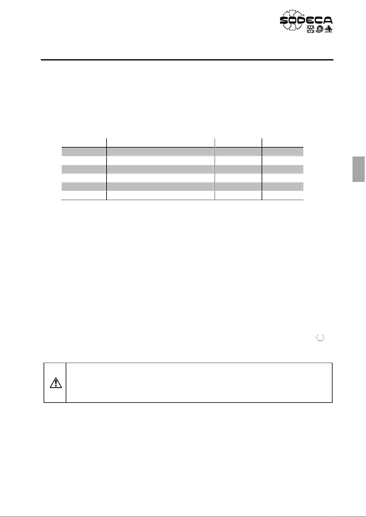
7.2 SETPOINT ADJUSMENT OF THE CO2 CONCENTRATION
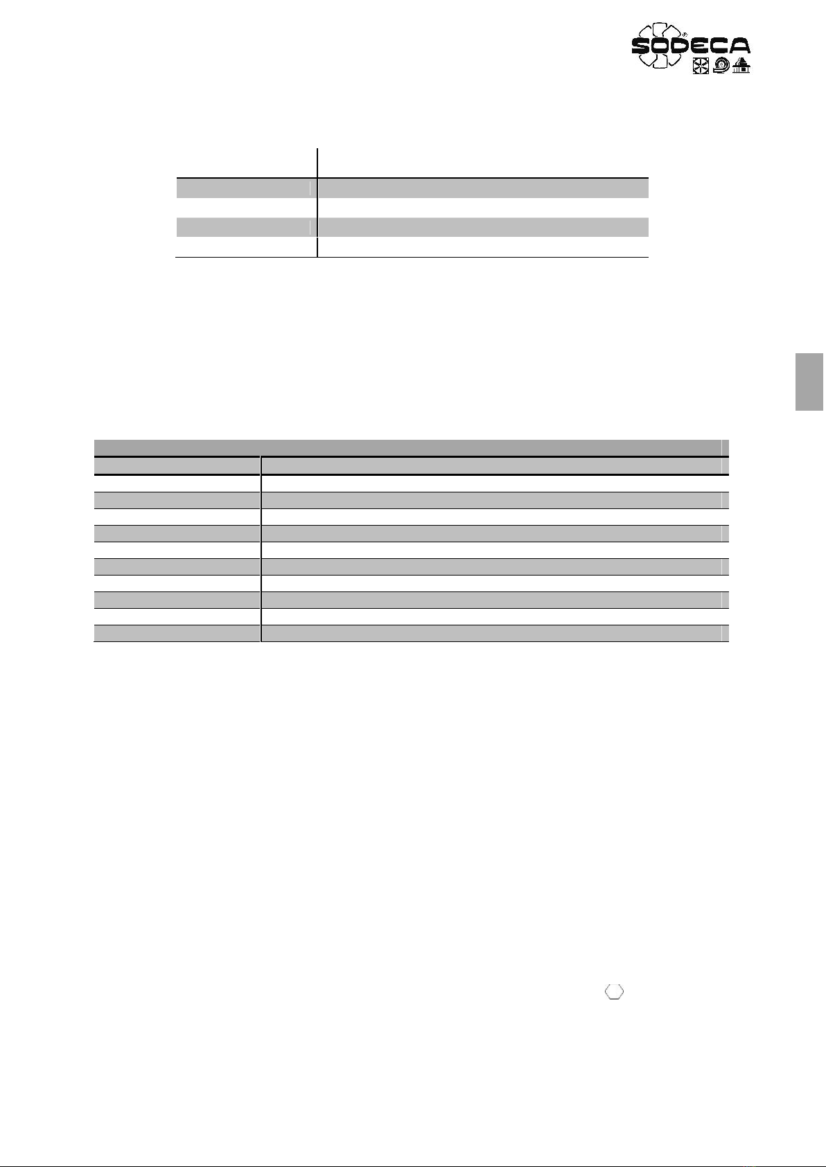
The setpoint is adjusted in the parameter. This parameter is shown as a percentage and will translate to a different
value of CO2concentration in ppm, subject to the chosen scale of the probe.
Scale
CO2concentration in ppm
per every 10% of the Setpoint
450-1850 ppm
140 ppm*
0-1000 ppm
100 ppm
0-1500 ppm
150 ppm
0-2000 ppm
200 ppm
(*) Increase for every 10%, add 450 ppm to obtain the real value
7.3 WIRING
Before the start of the programming, wire the L1-L2-L3 input phases when using three phase equipment and wire the
L1-L2/N input phases when using single phase equipment.
Once the “CO2” control mode is selected, that is after introducing the parameters of the CO2mode table (section 7.1),
wire the drive as seen in the picture. (See Fig. 9.).
The RUN signal must be connected between the terminals 1 & 2, and the switch is always closed, the drive will start
automatically when given power. If the user wants to stop the operation with a selector, timer, etc.… Set up a free
potential contact in series between the terminals 1 & 2.
7.4 PROBE SI-CO2 IND CONFIGURATION
It’s advised to adjust the scale of the probe SI-CO2 IND between 0 and 1000 ppm and the output signal 0-10 V. This
adjustment by means of the jumpers JP5 and JP1 respectively. Remove the cover of the probe to find this jumpers. (See
Fig. 10)
7.5 “CO2” OPERATION MODE
1. Close the RUN switch connected between the terminals 1 & 2 to start the drive. The display will show and
the drive will increase the speed until reaching the objective speed. This speed is subjected to the CO2
concentration level detected by the probe and the setpoint adjusted in .
2. If the CO2 level goes over the setpoint adjusted in the drive will increase the speed in order to decrease the
CO2 level below the setpoint.
3. If the CO2 level goes below the setpoint adjusted in the drive will decrease the speed in order to keep the
CO2 level below the setpoint.
4. If the user wants the drive to be always working, short-circuit the terminals 1 & 2 with a copper wire.
5. If the parameter has a value >0.0s, the drive will disconnect automatically when the CO2 level goes below
the setpoint for a certain amount of time, adjusted in this parameter. If this feature is active and the CO2 level goes
below the setpoint for an amount of time higher than the one set in , the drive will stop even when the RUN
switch is closed and won’t start again until the CO2 level goes over the setpoint.
6. While the drive is ON, the user can see the motor consume pressing the Navigator key >2 seconds.
VSD*/A Wirings
Terminal VSD*/A
Description
L/N+PE
Single phase input, only for VSD1/A
L1/L2/L3+PE
Three phase input, only for VSD3/A
U/V/W+PE
Three phase motor output
1
+24 VDC (100 mA)
2
Run signal
6
Analog input 1
7
0 V analog input
9
0 V
10
Output relay
11
‘Drive OK’ = Closed
13
EN
AP8. TEMPERATURE MODE
This section explains how to configure the “TEMPERATURE” control mode. This mode allows the drive to regulate the
speed of the ventilator as well as the warm or cold air inlet through a frequency inverter VSD*/A depending on the
temperature detected by the analogic sensor. Inverter starting is done from an external control (selector).
8.1 PROGRAMMING
Use the next table to change to, or modify, the TEMPERATURE mode.
Table “TEMPERATURE”
1. In order to make the regulation more dynamic, change the oparameters. Increase until the output
is fast enough. The increase as much as possible and stop before the system oscillates.
2. If we need warm air inlet we should configure to 0, on the contrary, if we need cold air inlet we should
configure to 1.
3. See sections 8.2 and 8.3 for the setpoint configuration.
8.2 PROBE SI-TEMP IND CONFIGURATION
Is recommended to adjust the output signal to 0-10V and the sensor SI-TEMP IND measuring scale. This adjustment by
means of the jumpers JP1 and JP2 respectively. Remove the cover of the probe to find this jumpers. (See Fig. 15).
Parameter
Description
Adjustment
Units
Maximum Frequency
50.0
Hz
Minimum Frequency
20.0
Hz
Acceleration Ramp Time
5
s
Deceleration Ramp Time
5
s
Motor Rated Current
x.x
A
Primary Command Source
5
Extended Menu Access code
101
Analog Input 1 Signal format
U 0-10
V
PI Controller Proportional Gain
0.2
%
PI Controller Integral Time
1.0
s
PI Controller Operating Mode
0 - 1
PI Digital Setpoint
xx.x
%
PI Feedback Source Select
1
ATTENTION: If there’s a power loss while the ventilator is working and the RUN switch is
closed, the drive will enter the stop stage and show on the display. Once the power is
restored, if the RUN switch is still closed, the drive will maintain the stop status. In order to start
again, the RUN switch must be opened and closed again. This operation can be modified
setting the mode in the parameter.
14
EN
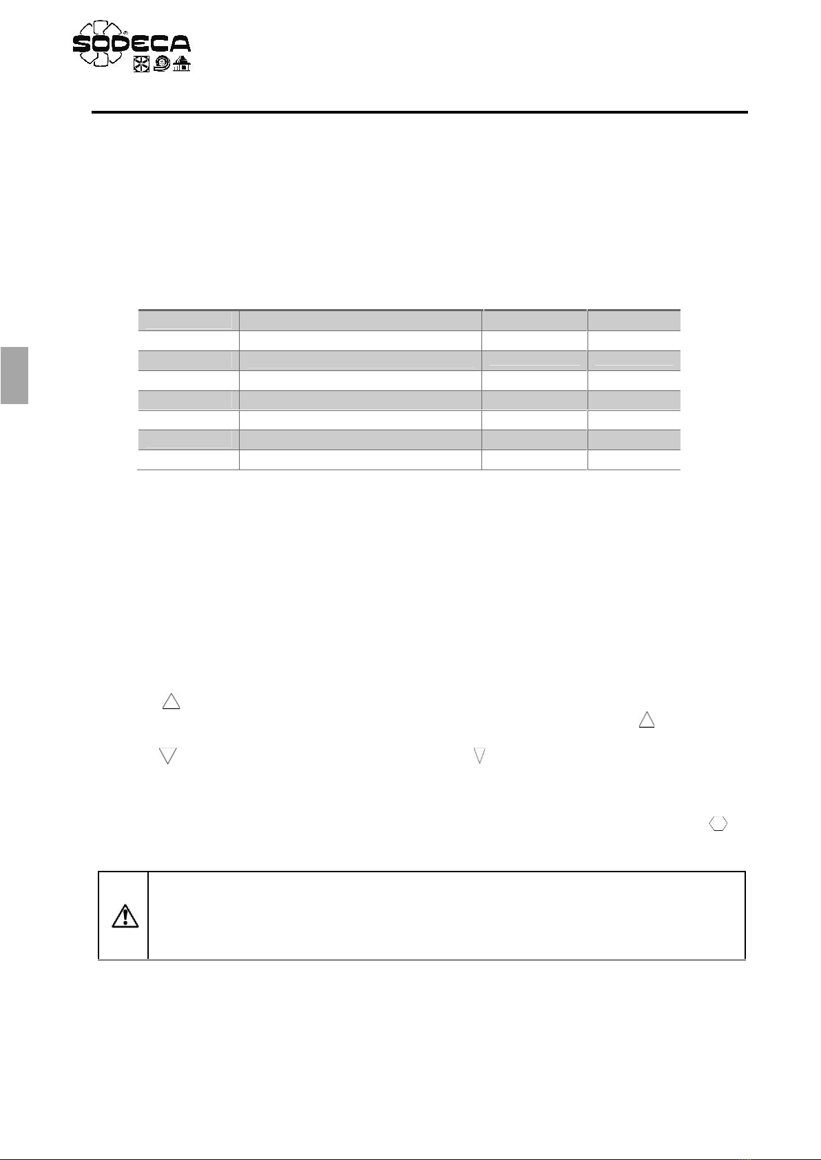
8.3 SETPOINT ADJUSMENT OF THE CO2 CONCENTRATION
The setpoint is adjusted in the parameter. This parameter is shown as a percentage depending on the sensor SI-
TEMP IND scale chosen in JP2 it has a different temperature value in ºC (Fig. 15).
Scale
CO2concentration in ppm
per every 10% of the Setpoint
0 – 30ºC
0ºC 0% - 30ºC 100%
10 – 40ºC
10ºC 0% - 40ºC 100%
20 – 50ºC
20ºC 0% - 50ºC 100%
0 – 50ºC
0ºC 0% - 50ºC 100%
8.4 WIRING
Before the start of the programming, wire the L1-L2-L3 input phases when using three phase equipment and wire the
L1-L2/N input phases when using single phase equipment.
Once the “TEMPERATURE” control mode is selected, that is after introducing the parameters of the Temperature mode
table (section 8.1), wire the drive as seen in the picture. (See Fig. 14). The RUN signal must be connected between the
terminals 1 & 2, and the switch is always closed, the drive will start automatically when given power. If the user wants to
stop the operation with a selector, timer, etc.… Set up a free potential contact in series between the terminals 1 & 2.
8.5 “TEMPERATURE” OPERATION MODE
1. Close the RUN switch connected between the terminals 1 & 2 to start the drive. The display will not show to
start cold or warm air inlet, depending of the parameter configuration, until reaching the set point configured
in .
2. If the parameter is set at 0 and the temperature exceeds the set point value configured in ,the inverter
VSD*/A will decrease the speed in order to keep it on the configured value. On the contrary, if the temperature
decreases below the set point configured in ,the inverter VSD*/A will increase the speed in order to keep it
on the configured value.
3. If the parameter is set at 1 and the temperature exceeds the set point value configured in ,the inverter
VSD*/A will increase the speed in order to keep it on the configured value. On the contrary, if the temperature
decreases below the set point configured in ,the inverter VSD*/A will decrease the speed in order to keep it
on the configured value.
4. If the user wants the drive to be always working, short-circuit the terminals 1 & 2 with a copper wire.
5. If the parameter has a value >0.0s, the drive will disconnect automatically. In this way, even keeping the run
connection, if the temperature is the desired, the inverter will stop and will show in the display, starting
again when is necessary according to the set point value configured in .
While the drive is ON, the user can see the motor consume pressing the Navigator key >2 seconds.
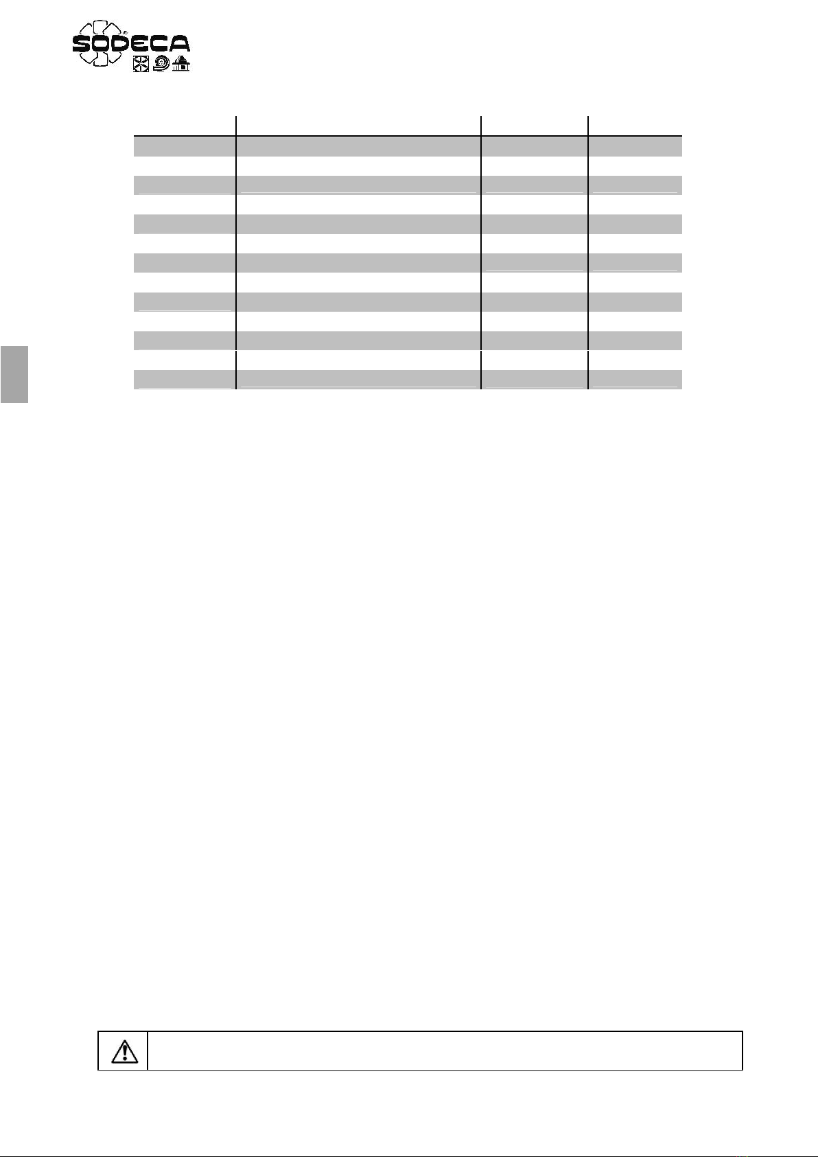
VSD*/A Wirings
Terminal VSD*/A
Description
L/N+PE
Single phase input, only for VSD1/A
L1/L2/L3+PE
Three phase input, only for VSD3/A
U/V/W+PE
Three phase motor output
1
+24 VDC (100 mA)
2
Run signal
6
Analog input 1
7
0 V analog input
9
0 V
10
Output relay
11
‘Drive OK’ = Closed

15
EN
AP9. PRESSURE CONTROL MODE – VSD1-P, VSD3-P
This section explains how to configure the “PRESSURE CONTROL”control mode. This mode allows the drive to
regulate the speed of the ventilator depending on the overpressure between to places.
9.1 PROGRAMMING
Use the next table to change to, or modify the pressure control mode.
Table “PRESSURE CONTROL”
1. In order to make the regulation more dynamic, change the oparameters. Increase until the output
is fast enough. The increase as much as possible and stop before the system oscillates.
2. See section 9.2 for the setpoint configuration.
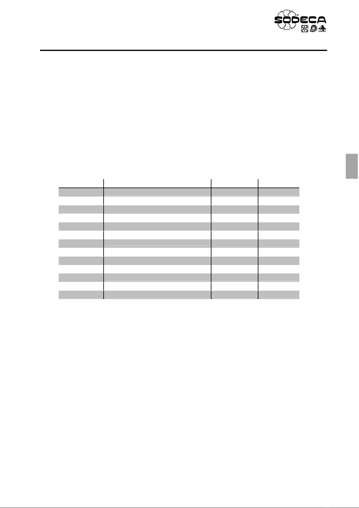
9.2 PRESSURE SETPOINT ADJUSTMENT
The pressure setpoint is adjusted in the parameter. The value read by the drive is shown in the only-read
parameter, if the probe has a display the user will be able to see the value directly. This parameters are shown
as percentages and will translate to a different value of Pa, subject to the chosen scale of the probe.
Scale
Pressure in Pa
for every 10% of the Setpoint
Scale
Pressure in Pa
for every 10% of the Setpoint
±100 Pa
20 Pa*
0-1000 Pa
100 Pa
0-100 Pa
10 Pa
0-1500 Pa
150 Pa
0-250 Pa
25 Pa
0-2000 Pa
200 Pa
0-500 Pa
50 Pa
0-2500 Pa
250 Pa
(*)Increase for every 10%, subtract 100 Pa to obtain the real value
Parameter
Description
Adjustment
Units
Maximum Frequency
50.0
Hz
Minimum Frequency
20.0
Hz
Acceleration Ramp Time
10
s
Deceleration Ramp Time
10
s
Motor Rated Current
x.x
A
Primary Command Source
5
Extended Menu Access code
101
Analog Input 1 Signal format
U 0-10
V
PI Controller Proportional Gain
0.2
%
PI Controller Integral Time
3.0
s
PI Controller Operating Mode
0
PI Reference (Setpoint) Source Select
0
PI Digital Setpoint
xx.x
%
PI Feedback Source Select
1
ATTENTION: If there’s a power loss while the ventilator is working and the RUN switch is closed,
the drive will enter the stop stage and show on the display. Once the power is restored, if
the RUN switch is still closed, the drive will maintain the stop status. In order to start again, the
RUN switch must be opened and closed again. This operation can be modified setting the
mode in the parameter.
Popular DC Drive manuals by other brands


SOMFY
SOMFY OXIMO BASIC WF RTS instructions

Danfoss
Danfoss VLT 6000 HVAC Series Design guide

Lenze
Lenze 8200 motec E82ZMFBC001 Mounting instructions

Vertiv
Vertiv Liebert GXT RT Series Quick installation guide

Delta Electronics
Delta Electronics AC Servo Drive ASDA-AB user manual

Deif
Deif IMD 100 CONFIGURATION AND VERIFICATION INSTRUCTIONS