WEG W21 User manual

Motors | Automation | Energy | Transmission & Distribution | Coatings
--
Quick Guide
快速指南
W21 Magnet Drive System

2 | W21 Magnet Drive System®
Quick Guide
中文
3
English
14
Read carefully this manual before installing and configuring the
equipment
This manual contains all necessary information for the installation and configuration of
the W21 Magnet Drive System. In order to ensure safety and proper operation of the
equipment, follow the instructions of this guide. For further information or explanations,
check our FAQ at www.weg.net/br/faq or contact Customer Service at +86-513-
85920153.
在安装和配置设备之前,请仔细阅读本手册的指示说明
本手册包含安装和配置 W21 Magnet 驱动系统的所有必要信息。为确保设备的安全
和正常运行,请按照本指南的说明进行操作。欲了解更多信息或解释,请登陆 www.
weg.net/br/faq 查询我们的常见问题或联系客户服务部门,电话 +86-513-85920153.

W21 Magnet Drive System®| 3
Quick Guide
1 - Technology
W21 Magnet Drive System is a system composed of the W21 Magnet permanent magnet synchronous
motor and the WEGPM frequency inverter.
The W21 Magnet motor features three-phase stator winding, similar to an induction motor, and rotor
assembled with permanent magnets instead of a squirrel cage. The permanent magnets eliminate the need
of current induction on the rotor (magnetizing current); therefore, with no load the motor presents a very low
current, just enough to make up for the losses. Besides the magnetizing current, the W21 Magnet does not
require slip compensation either, since the shaft speed does not vary with the load.
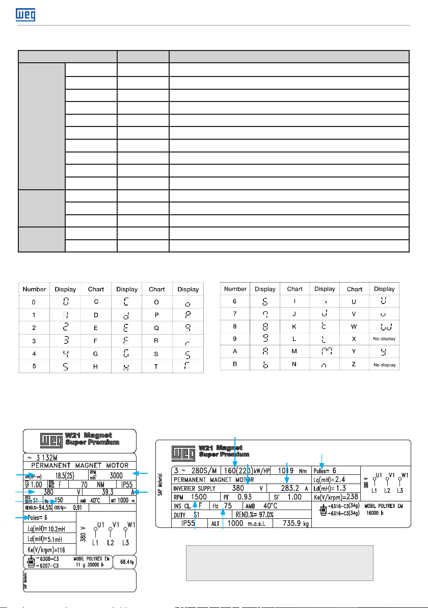
All W21 Magnet motors present a single configuration of six poles.
FNote!
Since this motor is not designed to be connected directly to the power line, all the motors of this line
present a single configuration of six poles and variable electric frequency. For example, the electric
frequency of the 1500 and 3000 rpm motors is:
1500 rpm x 6 poles = 75 Hz
120
3000 rpm x 6 poles = 150 Hz
120
FNote! W21 Magnet motors can be driven by the PM with encoder and Sensorless PM control options only.
2 - Safety measures
Any service on the internal parts of the motor must be performed by qualified personnel
only, since, due to the attraction between metallic parts caused by the magnets, risk of
accident is present both in the assembly and disassembly of the motor.
People that use pacemakers cannot handle these motors. The permanent magnets can
also cause disturbances or damages to other electric equipment and components during
service.
gBefore opening the terminal box of the motor, make sure the motor shaft is not spinning.
gNever touch the motor terminals while the rotor is spinning, because, even with the inverter shut down,
risk of electric shock is present. If it is observed the possibility of the load to accelerate the motor shaft, it
is necessary to install a disconnecting device between the inverter and motor terminals.
gW21 Magnet motors feature PTC temperature sensors which must be connected to the inverter so that
the motor will be shut down in case of overheating.
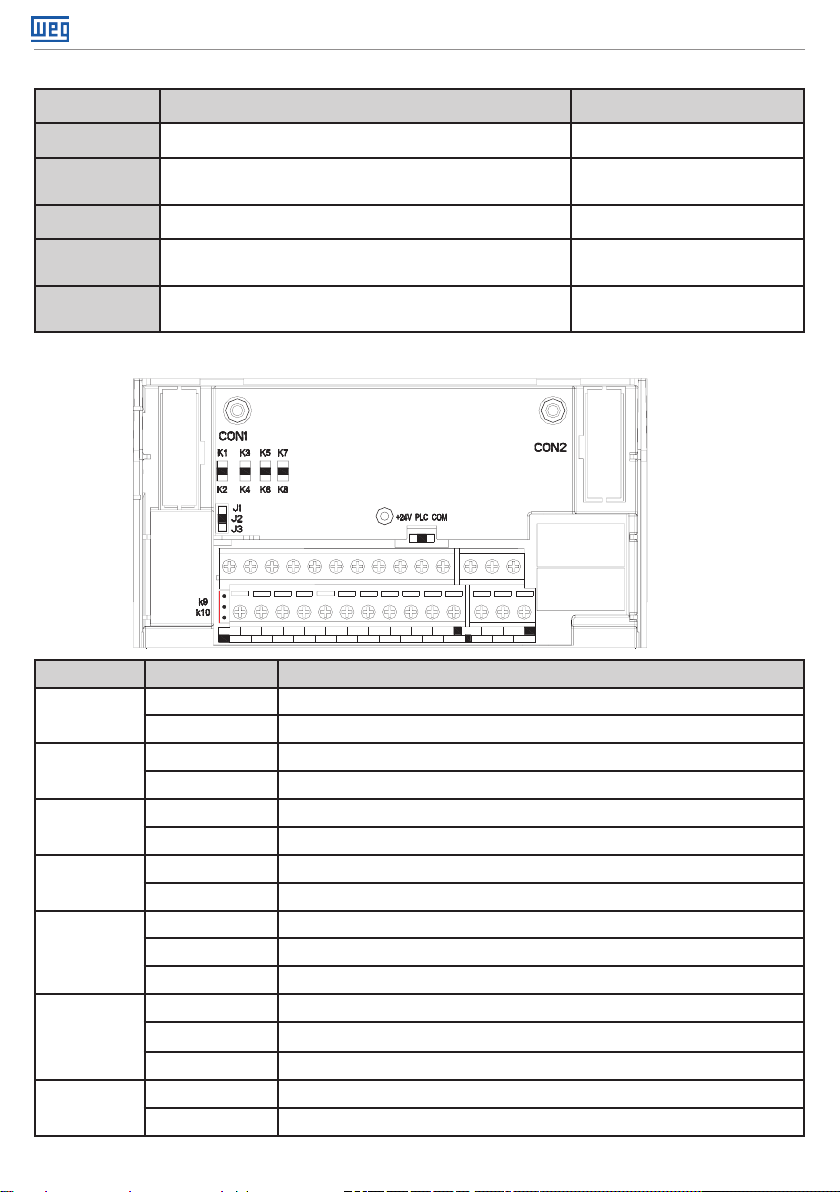
In order to connect the PTC temperature sensor, it needs to connect the input X7 & COM (refer to section
3 - Inverter Installation and Connections - Standard Connection Diagram) and setting the function F2.06 to
9: External Fault Input (refer to Section 4 - Configuration of the inverter) where X7 shall be set as Normally
Closed.
English
For further information on the motor installation and maintenance, refer to the instruction booklet supplied with it.
FNote!

4 | W21 Magnet Drive System®
Quick Guide
Standard Connection Diagram
●
Standard Connection Diagram
notice2
notice:defaultsettingsinbracket
notice1
TA1
TB1
TC1
+24V
Y
shieldedtwistedpaircable
_
mA
20
10
0
-
+
0
5
10
V
_
+-
GND
A01
V
W
U
M
~
shieldedcables
(nearinvertergroud)
E
(groundresistorlow
than10 )
W
V
U
outputreactor
DCreactor
brake
resistor
short
circuit
P1
+
( )
R
brakemodule
voltagemodelanaloginput
currentmodelanaloginput
+10V
R
T
S
ACinput
AI
GND
AS
VS
shieldedtwistedpairline)
inputpulse
X7
(reversaljogrunning)
(forwardjogrunning)
(reversalrunning)
(forwardrunning)
(freestop)
(faultreset)
(none)
COM
X3
X4
X6
X5
X1
X2
PB
( )
+
(-)
inverter
S
T
R
GND
A02
COM
AC220V
AC0V
K3
K4
maxoutput
3A/240VAC
5A/30VDC
1+24Vmax output
:
DC24V/100mA
A01/A02 used as frequency or
voltage output
,maxcurrent
2mA
2VS/AIterminal resistor
:
75K
1.+10V terminals max input 50mA
notice:
2Y max output
:
DC24V/50mA
notice:
2
standforcontrolcircuitterminal
notice:standformaincircuitterminal
1
shieldedtwistedpair
cable(nearinverterground)
inputreactorconnector
circuit
breaker
(
0~5V
)/(
0~10V
)
(
0~20mA
)/(
4~20mA
)
3AS terminal resistor
:
250
notice:
+
( )
notice4
PUL
X7
PUL
+24V
PLC
COM
current/voltageanaloginput
J1
J2
J3
K1
K2
K5
K6
TA2
TB2
TC2
AC220V
AC0V
A+
B-
RS485communication
120
K7
K8
analogoutputmonitor
3 - Inverter installation and connections
Read the WEGPM User’s Manual which is supplied with the inverter before installing, powering up or
operating the inverter.
FNote!
gInstall the inverter according to Chapter 3 - Installation and connections of the Manual.
gPrepare the drive and power up the inverter according to Chapter 4 - configuration of the inverter of the
Manual.
Note:
1.When installing DC reactor, make sure to dismantle the short connector between terminal P1 and (+).
2.NPN or PNP transistor signal can be selected as input of multi-function input terminal (X1~X7/PUL). Inverter built-in power supply
(+24V terminal) or external power supply (PLC terminal) can be chosen as bias voltage. Factory setting ‘+24V’ short connect with ‘PLC’.
3. Analog monitor output is the special output for meters such as frequency meter, current meter and voltage meter. It can’t be used for
control operations such as feedback control.
4. As there are multi pulse styles, please refer to the line connect mode description details.

W21 Magnet Drive System®| 5
Quick Guide
• Auxiliary Terminal Output Capacity
Terminal Function Definition Max Output
+10V 10V auxiliary power supply output, constitutes loop with GND. 50mA
A01/A02 Analog monitor output, constitutes loop with GND. Max output 2mA as frequency,
voltage signal,
+24V 24V auxiliary power supply output, constitutes loop with COM. 100mA
YCollector open circuit output; can set the
action-object by program. DC24V/50mA
TA1/TB1/TC1
TA2/TB2/TC2
Passive connector output; can set the action-object
by program.
3A/240VAC
5A/30VDC
• Connection Function Specification of Switch Terminals
AS VS GND
GND
AO2AO1 X1 X2
AI +10V COMTC1
PLCTA1
A+ +24V
X7/PUL
X4
X3 X5 TB2
X6 TA2
B- YTB1
COMTC2
Switch Terminal Selecting Position Function Specification
S1 K1 AO1:0~20mA or 4~20mA current output
K2 AO1:0~10V voltage output
S2 K3 AI:0~20mA or 4~20mA input current
K4 AI: 0~10V input voltage
S3 K5 AO2: 0.0~50kHz (J1 on), open collector circuit output
K6 AO2:0.0~50kHz (J1 on), active source output
S4 K7 RS485: connect with 120Ω terminal resistor
K8 RS485:connect without 120Ω terminal resistor
S5
J1 AO2:0.0~50kHz frequency output
J2 AO2:0~20mA or 4~20mA current output
J3 AO2:0~10V voltage output
S6
+24V Short +24V terminal and PLC terminal
PLC PLC terminal receiving external power input
COM Short PLC terminal and COM terminal
S7 K9 Disconnect GND terminal and PE discharge loop
K10 Connect GND terminal and PE discharge loop

6 | W21 Magnet Drive System®
Quick Guide
4 - Configuration of the inverter
Figure - HMI of Inverter
Key Name Function
Menu Key
Enter function menu when standby or running. Press this key to return when modifying
parameter. Press for 1 sec to enter condition monitoring interface when in standby or running
condition.
Confirm/
modify key
Press to modify parameter when in menu interface. Press again to confirm after modifying.
Press to change LED monitoring items at down time when in standby or running condition.
Up/down
key
Select parameter group in menu interface. Modify parameter in modifying interface. Modify
given frequency, PID, given torque or magnetic powder clutch given torque when at standby
or condition monitoring state (When given frequency, PID, given torque or magnetic powder
clutch given torque are set by keyboard, please set [F4.04])
Shift key Select digit of function number modified by up/down key; Select
parameter digits modified by up/down key.
4.1 - Inverter’s key functions
Forward run
key
When run/stop is controlled by keyboard, press this key, the inverter forwardly rotate and the
indicator is always on. When reverse, the indicator sparks.
Jog/reverse
key
This key function can be defined by parameter [F4.02]. Press it, the machine reverses and
indicator is off if this key is defined as REVERSE; the machine jogs and indicator is on if this
key is defined as JOG.
Stop/reset
key
The machine stops if press it while run/stop is controlled by keyboard. Its efficiency range is
defined via function no [F4.03]. Inverter resets if press it in fault state (the machine would not
reset if the fault is not solved).
Keyboard
potentiometer
Can be used as input channel for given frequency, upper frequency limit,
given torque, given PID or PID feedback setting

W21 Magnet Drive System®| 7
Quick Guide
gIn order to perform the oriented start-up, follow the procedures described below by entering the motor
nameplate data.
1
24
4
6
2
1 - Poles 4 - Rated Speed
2 - Output 5 - Rated Voltage
3 - Frequency 6 - Rated Current
56
5
1
3
3
4.2 - Indicator light meanings
Name Status Meaning
Unit Indicator
Light
Hz Spark Digital display given frequency.
Hz On Digital display output frequency.
A On Digital display actual output current.
V On Digital display input voltage.
V Spark Digital display output voltage.
S On Time unit is second.
S Spark Time unit is ms, min, or h.
RPM On Digital display motor speed.
% Spark Digital display given PID.
% On Digital display PID feedback.
State
Indicator
Light
FWD On Inverter is forwardly rotating.
FWD Spark Inverter is reversely rotating.
FWD Off Inverter stops.
Function
indicator light
REV/JOG On Jog.
REV/JOG Off Reverse.
4.3 - Number and characters chart
4.4 - Procedures for oriented start-up

8 | W21 Magnet Drive System®
Quick Guide
Procedure for oriented start-up (using nameplate data of motor 18.5kW as example)
1Press “PRG”2- Select group “F0”.
- Press “Set”.
3
- Set “F0.00”
according to
motor control
algorithm “5: PM
Vector Control”.
- Press “Set”.
4
- Set “F0.11”
according to the
upper frequency.
- Press “Set”.
5
- Set “F0.08”
according to the
frequency aim.
- Press “Set”.
6
- Set “F0.09”
according to the
maximum frequency.
- Press “Set”.
7
- Select group
“F5”.
- Press “Set”.
8
- Set “F5.01”
according to the
motor number of
poles.
- Press “Set”.
9
- Set “F5.02”
according to
the motor rated
power.
- Press “Set”.
10
- Set “F5.03”
according to
the motor rated
frequency.
- Press “Set”.
11
- Set “F5.04”
according to
the motor rated
speed.
- Press “Set”.
12
- Set “F5.05”
according to the
motor rated voltage.
- Press “Set”.
13
- Set “F5.06”
according to
the motor rated
current.
- Press “Set”.
14
- Set “F5.12” as “2:
Static Self-Tune“.
- Press “Set”.
To end press “Reset”. To run the motor press “FWD”.
FNote!
The configuration through the “Oriented Start-up” results in the automatic modification of the content of
parameters and internal variables of the inverter regarding the control and the motor. That ensures a stable
operation of the control and maximum efficiency of the motor.

W21 Magnet Drive System®| 9
Quick Guide
5 - Solution of faults
This chapter explains the display content and measures of the inverter fault, alarm and operation fault. In addi-
tion, the poor condition caused by the inverter and motor failures and the corresponding processing measures
will be briefly described. Tuning Guide on trial use is also referred to in this chapter.
5.1 - Fault Types
Type Inverter Action When Fault Happens
Equipment Fault
When inverter detects a fault, the following conditions would happen:
●Keyboard display character showing fault content.
●Inverter output stops. Motor free slide stops.
●When function [F2.29] is 3(output fault), Y terminal outputs valid open-collector digital
output.
●When function [F2.30\F2.31] is 3(fault output), TA1-TC1, TA2-TC2 terminals output
open passive digital output.
●For faults like OL, OC, SC, OV, UL2, if [FA.22] is not 0, the inverter will restart auto-
matically after the time interval set by [FA.23].
External Fault
In certain application occasions, external related equipments fault signals are consi-
dered in the inverter control system as usage of monitoring, protection and switch con-
trol. At this time, if one multi function terminal is defined as “external fault”, and when
the external related equipments fault signals are effective, the inverter stops output and
give out alarm signal.
5.2 - Fault Information and Details
Keyboard
Display
Fault
Code Fault Type Possible Causes Treatment Measures
L.U.1 Too low
when stop
●Power supply is too
low
●Voltage detection
circuit is abnormal
●Check input power, eliminate fault.
●Seek support from vendor.
E.LU2
Under
voltage in
run
●Power supply is too
low
●Power capacitance
is too small, or there
is enormous impact
current in the power
grid.
●Inner DC main con-
tactor is not closed.
●Check input power, eliminate fault.
●Improve power-supply system.
●Seek support from vendor.
E.oU1 Acc over-
voltage
●Power voltage fluc-
tuation over limit.
●Start motor when
running.
●Detect power voltage and eliminate
fault.
●Restart motor until it totally stop; Set
F1.00 to 1or 2.

10 | W21 Magnet Drive System®
Quick Guide
E.oU2 Dec over-
voltage
●Deceleration time is too
short.
●Load potential energy or
inertia is too large.
●Power voltage fluctua-
tion over limit.
●Prolong deceleration time properly.
●Reduce load inertia or improve
inverter capacitance or add braking
unit.
●Detect input power and clear fault.
E.oU3
Constant
speed
over-
voltage
●Power voltage fluctua-
tion over limit.
●Detect input power voltage and
eliminate fault.
●Install input reactor.
E.oU4
Over-vol-
tage when
stop
●Power voltage fluctua-
tion over limit.
●Check input power, eliminate fault.
●Seek support from vendor.
E.oC1 Acc over-
-current
●Acceleration time is too
short.
●Start motor when run-
ning.
●V/F curve setting is not
suitable. Or torque boost
too high.
●Inverter capacitance is
too small.
●Prolong acc time.
●Restart motor until it totally
Stop; Set F1.00 to 1or 2.
●Reset V/F curve or torque boost
value.
●Select inverter with right capacitan-
ce.
E.oC2 Dec over-
-current
●Deceleration time is too
short.
●Load potential energy or
inertia is too large.
●Power voltage fluctua-
tion over limit.
●Prolong deceleration time.
●Connect external braking resistan-
ce or braking unit.
●Select inverter with right capacitan-
ce.
E.oC3
Constant
speed
over-
-current
●Sudden load change.
●Power grid voltage is too
low.
●Check load change and eliminate it.
●Check input power, eliminate fault.
E.oL1 Motor
over-load
●V/F curve setting is not
suitable. Or torque boost
too high.
●Power grid voltage is too
low.
●Wrong overload protec-
tion setting.
●Locked-rotor run or too
heavy load.
●Universal motor runs at
low speed for a long time
●Reset V/F curve or torque boost
value.
●Check input power, eliminate fault.
●Unreasonable F5.06 setting.
●Adjust load or select inverter with
right capacitance.
●If long-term low-speed operation
is needed, please choose special
motor for inverter.

W21 Magnet Drive System®| 11
Quick Guide
E.oL2 Inverter
over-load
●Load is too heavy.
●Acceleration time is too
short.
●Start motor when running.
●V/F curve setting is not sui-
table. Or torque boost too
high.
●Select inverter with right capaci-
tance.
●Prolong acceleration time
●Restart motor until it totally
stops. Set [F1.00] as 1or2.
●Reset V/F curve or torque boost
value.
E. SC System
abnormal
●Acceleration time is too
short.
●Short circuit between inver-
ter output phases or earth.
●Module is damaged.
●Electromagnetic disturb.
●Prolong acceleration time pro-
perly.
●Check peripheral equipments
and restart after fault eliminating.
●Seek support from vendor.
●Check system wiring, earth,
shield and deal as required.
E.oH1 Inverter
over-heat
●Temperature is too high.
●Air channel is blocked.
●Fan connection parts loose.
●Fan is damaged.
●Temperature detection
circuit fault
●Meet the environment require-
ment.
●Clear the air channel.
●Check and reconnect the wire
●Change the same new fan.
●Seek support from vendor.
E.oH2 Rectifier
over-heat
●Temperature is too high.
●Air channel is blocked.
●Fan connection parts loose.
●Fan is damaged.
●Temperature detection
circuit fault
●Meet the environment require-
ment.
●Clear the air channel.
●Check and reconnect the wire.
●Change the same new fan.
●Seek support from vendor.
E.Fb1
PID feed-
back over
upper limit
●PID feedback wire breaks.
●PID feedback channels
parameter is wrong.
●Analog feedback channel is
abnormal.
●Check PID feedback wire.
●Check the PID feedback channel
parameter setting.
●Seek support from vendor.
E.Fb2
PID feed-
back over
lower limit
●PID feedback wire breaks.
●PID feedback channels
parameter is wrong.
●Analog feedback channel is
abnormal.
●Check PID feedback signal wire.
●Check the PID feedback channel
parameter setting.
●Seek support from vendor.
E.TE1
Motor
static
detection
fault
●Detection overtime
●Start static detection when
motor is running.
●Capacitance difference is
too big between motor and
inverter.
●Motor parameter setting
mistake.
●Check motor connection wire.
●Detect after motor stops totally.
●Change inverter model.
●Reset parameter according to
nameplate.

12 | W21 Magnet Drive System®
Quick Guide
E.TE2
Motor
rotation
detection
fault
●Detect when motor is
running.
●Detect with load.
●Detection overtime
●Capacitance difference is
too big between motor and
inverter.
●Motor parameter setting
mistake.
●Detect after motor stops totally.
●Re-detect without load.
●Check motor connection wire.
●Change inverter model.
●Reset parameter according to na-
meplate.
E.EEP Storage
failure
●Electromagnetic disturb in
storage period.
●EEPROM damage.
●Resume load and save.
●Seek support from vendor.
LIFE Reserved ● ● Seek support from vendor.
E.ILF
Input side
open pha-
se
●3-phase input power open
phase.
●Check 3-phase power supply and
the phase.
●Check 3-phase power supply wi-
ring.
E.oLF
Output
side open
phase
●3-phase output power
open phase
●Check 3-phase output voltage
and current.
●Check wiring.
E.Gnd Output
earth
●Output earth terminal short
circuit. ●Check wiring and insulation.
E.HAL
Current
detection
fault
●Detect circuit fault.
●Phase imbalance
●Seek for technical support.
●Check motor and wiring.
E. EF
Inverter
external
fault
●Peripheral equipment fault
protection. ●Check peripheral equipment.
E.PAn
Keyboard
connect
fault
●Keyboard wire fault.
●Keyboard component
damage.
●Check keyboard wire.
●Seek support from vendor.
E. CE
Rs-
485com-
munication
fault
●Unsuitable baud rate set-
ting.
●Communication wire bre-
aks.
●Communication format
does not match upper
machine.
●Set suitable baud rate setting.
●Check communication wire.
●Set right communication format.
E.CPE Parameter
copy fault
●Parameter copy communi-
cation is fault.
●Copy keyboard is not
match the inverter.
●Check wire.
●Select the specified external key-
board model.

W21 Magnet Drive System®| 13
Quick Guide
E.ECF
Extend
card
connection
fault
●Communication between
extend card and frequency
inverter overtime.
●Extended card does not ma-
tch with frequency inverter.
●Check connector, and re-insert
wire.
●Choose the named card.
E.PG
PG card
connection
abnormal
●PG card and inverter con-
nection failure ●Check the connection
E.PID PID feed-
back failure
●PID feedback upper limit
of disconnection alarm is
improper
●PID feedback lower limit
of disconnection alarm is
improper
●PID feedback wiring unrelia-
ble
●Sensor with feedback failure
●Feedback input loop failure
●Confirm the sensor state, if
broken, change it.
●Repair the wiring.
●Confirm the setting value of
[Fb.16] and [Fb.17].

14 | W21 Magnet 驱动系统
快速指南
1 - 技术
W21 Magnet 驱动系统是由 W21 Magnet 永磁同步电机和 WEGPM 变频器组成的驱动系统。
W21 Magnet 电机具有三相定子绕组,类似于感应电动机,转子装有永磁体,而不是鼠笼式转子。永磁体
消除了在转子上所需的感应电流(励磁电流);因此,电机在空载状态下具有极低的电流,足以弥补电气
损耗。除了励磁电流以外,W21 Magnet 也不需要滑差补偿,因为轴转速不随负载而变化。
所有 W21 Magnet 电机均为单一的六极配置。
F注意 !
由于该电机没有被设计成直接连接供电电源,该产品线的所有电机均为单一的六极配置并可变频。举个例
子,1500 rpm 转速的电机和 3000 rpm 转速的电机频率分别为:
1500 rpm x 6 极= 75 Hz
120
3000 rpm x 6 极= 150 Hz
120
F注意 ! W21 Magnet 电机仅可由 PM 带编码器和 PM 无传感器控制选项来驱动。
2 - 安全措施
任何在电机内部部件的服务必须由具备专业资质的人员操作,由于金属部件之间的磁力吸引
力,因此,无论在电机的组装和拆卸过程中均存在风险。
使用心脏起搏器的人员不得操作此类电机。
永磁体也可以在服务过程中造成干扰或损坏其他的电气设备。
g在打开电机的接线盒之前,确保电机轴处于停止状态。
g绝对禁止在转子旋转时触碰电机的接线端子, 因为即便变频器处于关机状态,触电的危险依旧存在。如果
观察到负载有可能加速电机轴的可能性,有必要在变频器和电机端子之间安装断开装置。
gW21 Magnet 电机带有 PTC 温度传感器,它必须连接到变频器上,确保电机在过热的情况下被停机。
为连接PTC 温度传感器,可将输入信号与 X7 和 COM 端口连接 (端口位置参照 第3章-变频器的安装和连
接 - 标准连接图)并设置变频器参数组 F2.06 为 9: 外部故障输入 (设置方法参照第4章-变频器的配置) ,
注意,X7的端子极性应设置为常闭,即断开有效。
中文
如需更多关于电机安装和维护的信息,请参照随电机提供的安装维护操作手册。
F注意 !

W21 Magnet 驱动系统 | 15
快速指南
3 - 变频器的安装和连接
在安装,通电或操作变频器之前,请仔细阅读随变频器附送的 WEGPM 变频器用户手册。
F
g请根据本手册第三章 - 变频器的安装和连接 进行安装。
g请根据本手册第四章 - 变频器的配置 对变频器进行配置和通电。
注意 !
标准连接图
● 标准连接图
符号
注2
注:括号内的功能说明为变频器出厂值。
注1
模
拟
量
监
控
信
号
输
出
TA1
TB1
TC1
+24V
Y
双绞屏蔽电缆(近变频器端接地)
_
mA
20
10
0
-
+
0
5
10
V
_
+-
GND
A01
V
W
U
M
~
屏蔽电缆或铠装电缆
(近变频器端接地)
E
(接地电阻小于10欧姆)
W
V
U
输出电抗器
外接直流电抗器
外接制
动电阻
短接片
P1
+
( )
R
外接制动单元
电压型模拟量输入
电流型模拟量输入 +10V
频
率
控
制
输
入
R
T
S
交
流
电
源
输
入
AI
GND
AS
VS
双绞屏蔽电缆(近变频器端接地)
脉冲输入 X7
多
功
能
接
点
输
入
(反转点动)
(正转点动)
(反转运行)
(正转运行)
(自由停车)
(故障复位)
(外部故障输入)
COM
X3
X4
X6
X5
X1
X2
PB
( )
+
(-)
变频器
S
T
R
GND
A02
线圈
COM
AC220V
AC0V
线圈
K3
K4
接点最大输出:
3A/240VAC
5A/30VDC
1+24V端口最大输出:DC24V/100mA
A01/A02端口作为频率、电压类型
信号输出时,最大输出:2mA
2VS/AI端口内阻:75K
1+10V端口最大输出:50mA
注:
2Y端口最大输出:DC24V/50mA
注意:
2代表控制电路端子。
代表主电路端子;
图例: 符号
1
双绞屏蔽电缆(近变频器端接地)
输入电抗器接触器断路器
(0~5V)/(0~10V)
(0~20mA)/(4~20mA)
3AS端口内阻:250
注:
+
( )
注4
注3
PUL
X7
PUL
+24V
PLC
COM
电压/电流型模拟量输入
J1
J2
J3
K1
K2
K5
K6
TA2
TB2
TC2
AC220V
AC0V
线圈
A+
B-
RS485差分通迅120
K7
K8
注 : 1、安装 DC 电抗器时,请务必拆下 P1, (+) 端子间的短接片;
2、多功能输入端子 (X1~X7/PUL)可选择 NPN或PNP晶体管信号作为输入,偏置电压可选择变频器内部电源 (+24V
端子 ),也可以选择外部电源 (PLC 端子 ),出厂值图示转换开关拔至 +24 档表示 ‘+24V’ 与‘PLC’ 为短接状态。
3、模拟量监视输出为频率表、电流表、电压表等指示表专用的输出,不能用于反馈控制等控制类操作。
4、由于实际使用中存在多种脉冲类型,具体接线方式请参见详细描述。

16 | W21 Magnet 驱动系统
快速指南
● 辅助端子输出能力
端子 功能定义 最大输出
+10V 10V 辅助电源输出,与 GND 构成回路。 50mA
A01/A02 模拟量监控输出,与 GND 构成回路。 作为频率、电压类型信号时最大输出 2mA
+24V 24V 辅助电源输出,与 COM 构成回路。 100mA
Y集电极开路输出,可程序设定动作对象。 DC24V/50mA
TA1/TB1/TC1
TA2/TB2/TC2 无源接点输出,可程序设定动作对象。 3A/240VAC; 5A/30VDC
●转换开关功能图例及说明
COM
PLC
A+ +24VB- Y
AS VS GND
GNDAO2AO1
AI +10V TC1
TB2
TA2
TB1
TC2
TA1
X7/PULX6
COMX1 X2 X3 X4 X5
● 转换开关功能图例及说明
位号 选择位置 功能说明
S1 K1 AO1输出0~20mA 或4~20mA
K2 AO1输出0~10V
S2 K3 AI 输入0~20mA 或4~20mA
K4 AI 输入0~10V
S3 K5 AO2为0.0~50kHz输出时(J1开通),转AO2为开路集电极输出
K6 AO2为0.0~50kHz输出时(J1开通),转AO2为有源输出
S4 K7 RS485通讯接入120欧终端电阻
K8 RS485通讯断开120欧终端电阻
S5
J1 AO2接口0.0~50kHz频率输出
J2 AO2接口0~20mA电流输出或4~20mA电流输出
J3 0~10V电压输出
S6
+24V +24V与PLC短接
PLC PLC接收外部电源输入
COM PLC与COM短接
S7 K9 断开工作地GND与机壳PE泄放回路
K10 连接工作地GND与机壳PE泄放回路

W21 Magnet 驱动系统 | 17
快速指南
4 - 变频器的配置
变频器键盘界面
按键符号 按键名称 功能描述
菜单键 待机或运行时进入功能菜单界面;在参数修改状时,按下该键退出修改;待机
或运行时长按该键(1 秒),直接进入状态监控界面。
确认/修
改键
菜单界面时按下该键进入参数修改状态,修改完毕后再次按下该键确认修改
值;在待机或运行状态下按下该键可以直接更改停机时LED 监视项。
上下键
菜单界面时选择参数组;在参数修改状态时修改参数值;待机或运行监视状态下
修改给定频率、PID、转矩给定量、磁粉离合器转矩给定量(当给定频率、PID、
转矩给定量、磁粉离合器转矩给定量为键盘数字设定时,需设定[F4.04])。
移位键 菜单界面时用于选择上下键所修改的功能号的位数;参数修改状态时用于选择
上下键所修改的参数的位数。
4.1 - 变频器按键功能
正转运行键 当运行/停止由键盘控制时,按下该键变频器正转。正转运行时,状态指示灯常
亮,反转运行时,状态指示灯闪烁。
反转/点
动键
该键可以通过参数[F4.02]定义功能。当定义为反转键(REV)功能时,按下该键
变频器反转运行,按功能指示灯灭。当该键定义为点动键时,按下该键变频器
点动运行,按键功能指示灯亮。
停车/复
位键
当命令给定通道设定为键盘控制时,按下该键变频器停止运行;也可通过参数
[F4.03]定义其扩大有效范围;故障状态时按下该键变频器复位。
(当故障未消除时将不能复位)。
键盘电位器 可用做给定频率、上限频率、给定转矩、PID 给定、PID 反馈等设定值的
输入通道。

18 | W21 Magnet 驱动系统
快速指南
g为了定向启动的设置,请参照下面的步骤输入电机铭牌的数据。
1
24
4
6
2
1 - 极数 4 - 额定转速
2 - 功率 5 - 额定电压
3 - 频率 6 - 额定电流
56
5
1
3
3
4.2 - 指示灯含义
名称 状态 含 义
单位
指示灯
Hz 闪烁 数码管显示的值为给定频率。
Hz 亮数码管显示的值为输出频率。
A亮数码管显示的值为输出电流实际值。
V亮数码管显示的值为输入电压。
V闪烁 数码管显示的值为输出电压。
S亮表示时间单位为秒。
S闪烁 表示时间单位为毫秒、分或是小时。
RPM 亮表示此时4位数码显示的值为电机转速。
%闪烁 表示此时4位数码显示的值为PID给定量。
%亮表示此时4位数码显示的值为PID反馈量。
状态
指示灯
FWD 亮变频器正转运行中。
FWD 闪烁 变频器反转运行中。
FWD 灭变频器停机。
功能
指示灯
REV/JOG 亮该键定义为点动按键。
REV/JOG 灭该键定义为反转按键。
4.3 - 数字文字对照表
4.4 - 定向启动的设置步骤

W21 Magnet 驱动系统 | 19
快速指南
定向启动配置步骤 ( 以18.5kW电机铭牌数据为例)
1按“PRG”2- 选择 “F0” 组.
- 按“Set”.
3
- 根据电机控制
算法“5:PM矢
量控制”设定
“F0.00” .
- Press “Set”.
4
- 根据电机频率上限设
定 “F0.11” 。
- 按“Set”.
5
- 根据目标频率设
置“F0.08” 。
- 按“Set”.
6
- 根据最大频率设置
“F0.09” 。
- 按“Set”.
7- 选择 “F5”组.
- 按“Set”. 8
- 根据电机极数设置
“F5.01” 。
- 按“Set”.
9
- 根据电机额定功
率设置 “F5.02” 。
- Press “Set”.
10
- 根据电电额定电电设置
“F5.03” 。
- 按“Set”.
11
- 根据电机额定转
速设置 “F5.04”。
- 按“Set”.
12
- 根据电机额定电压设
置“F5.05” 。
- 按“Set”.
13
- 根据电机额定电
流设置 “F5.06” 。
- 按“Set”.
14
- 将“F5.12” 设置为
“2: Static Self-Tune“.
- 按“Set”.
结束设置按 “Reset”. 启动电机按 “FWD”.
F注意! 通过“定向启动”的配置,将自动修改变频器内与控制和电机相关的参数和内部变量的内容。 这确保了控
制的稳定操作和电动机的最大效率。

20 | W21 Magnet 驱动系统
快速指南
5 - 故障诊断和对策
本章对变频器的故障、警报、以及操作时的故障等,在变频器上的显示内容及其对策进行说明。另外,本章
还对变频器及电机的故障所引起的不良状况及其解决方法进行简单说明。关于试运行时变频器的调整指南也
请参照本章。
键盘显示 故障
代码
故障
类型 可能故障原因 故障对策
L.U.1 停机时
过低
● 电源电压太低;
● 电压检测电路异常。
● 检查输入电源,排除故障;
● 寻求厂家技术支持。
E.LU2 运行中
欠压
● 电源电压太低;
● 电网容量太小,或电网
内有较大冲击电流;
● 变频器内部直流主接触
器未吸合。
● 检查输入电源,排除故障;
● 改善供电系统;
● 寻求厂家技术支持。
E.oU1 加速过
电压
● 电源电压波动超限;
● 启动正在旋转的电机。
● 检测电网电压,排除故障;
● 等电机完全停止后再启动、将 [F1.00]
设置为 1 或者 2。
E.oU2 减速中
过压
● 减速时间设置过短;
● 负载势能或惯量太大;
● 电源电压波动超限。
● 适当延长减速时间;
● 减少负载惯量,或增大变频器容量,或
增设制动单元;
● 检查输入电源,排除故障。
种类 故障发生时的变频器的动作
设备故障
变频器检测出故障时,会出现以下状况:
● 键盘上出现表示故障内容的文字;
● 变频器输出被切断,电机自由滑行停止;
● 功能 [F2.29] 选择为 3(故障输出)时,Y 端子输出有效的集电极开路开关量输出;
● 功能 [F2.30\F2.31] 选择为 3(故障输出)时,TA1~TC1、TA2~TC2 端子输出闭合的无源
开关量输出,TB1~TC1、TB2~TC2 端子输出断开的无源开关量输出;
● 对于过载 (OL)、过流 (OC)、系统异常 (SC)、过压 (OU)、运行中欠压 (LU2) 类型的故障现
象,如果 [FA.22] 选择不是 0,此时,如果发生上述故障,变频器经过 [FA.23] 设定的时
间间隔后,自动重新启动。
外部故障
某些应用场合,将外部关联设备的故障信号纳入变频控制系统,作为监控、保护、切换控
制等用途,此时,如果定义了某个多功能接点输入端子为“外部故障”,当外部关联设备
的故障信号有效时,变频器封锁输出给出报警信号。
5.1 - 故障类型
5.2 - 故障信息及详细内容
Other manuals for W21
2
Table of contents
Other WEG DC Drive manuals

WEG
WEG CFW-11 Series User manual

WEG
WEG CFW100 series User manual

WEG
WEG MVW3000 Series Owner's manual

WEG
WEG CFW320 User manual

WEG
WEG DeviceNet CFW500 User manual

WEG
WEG CFW11M G2 Series User manual

WEG
WEG CFW700 Operating instructions

WEG
WEG bacnet CFW701 User manual

WEG
WEG CFW900 User manual

WEG
WEG CFW300 V1.3X Owner's manual

WEG
WEG CFW-11W Installation and operating instructions

WEG
WEG CFW100 series User manual

WEG
WEG CFW-11 Series Use and care manual

WEG
WEG CFW-11 Series Operating instructions

WEG
WEG Easy Drive CFW10 User manual

WEG
WEG CFW320 User manual

WEG
WEG ADW300 User manual

WEG
WEG CFW700 User manual

WEG
WEG MVW3000 Series User manual

WEG
WEG CFW300-KHMIR Quick guide