SODECA CAS User manual
Code: 1143691
Doc. Num: 0000006331 (2016-12-05)
www.sodeca.com
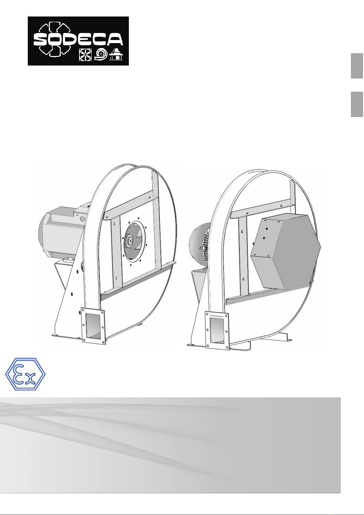
CAS – CAS/ATEX
CAS-S
PL
EN
Dokumentacja techniczno - ruchowa
User manual
Rys. 2
CAS-S
Rys. 3
Rys. 4
Zasilanie
230
230 / 400
400
400 / 690
400
230 / 400
Gwiazda
1/2 D
≥ D
D
Rys. 2
Rys. 1
Rys. 4.1 -
Schemat połączeń silników
jednobiegowych
230 230 / 400
400 400 / 690
400 230 / 400
Gwiazda
Zasilanie Napięcie
znamionowe
silnika
Połączenie
Trójkąt
Napięcie
znamionowe
silnika

Rys. 5
(Modele 50 Hz )
Model
Prędkość
(r/min)
230V
400V
690V
(kW)
(m3/h)
CAS
CAS-S
CAS
CAS-S
CAS
CAS-S
242-2T-0,33
2710
1,29
0,75
0,25
450
73
67
30
33
CAS
CAS-S
242-2T-0,5
2710
1,92
1,11
0,37
650
73
67
31
34
CAS
CAS-S
248-2T-0,75
2760
2,57
1,49
0,55
420
74
68
43,5
46,5
CAS
CAS-S
248-2T-1
2770
2,78
1,60
0,75
500
75
69
45
48
CAS
CAS-S
248-2T-1,5
2860
4,20
2,40
1,10
990
76
70
46,5
49,5
CAS
CAS-S
254-2T-1,5
2860
4,20
2,40
1,10
600
76
70
56,5
59,5
CAS
CAS-S
254-2T-2
2770
5,44
3,13
1,50
800
78
72
61,5
64,5
CAS
CAS-S
254-2T-3
2885
7,77
4,47
2,20
1300
80
73
63
66
CAS
CAS-S
260-2T-2
2770
5,44
3,13
1,50
500
77
71
75
80
CAS
CAS-S
260-2T-3
2885
7,77
4,47
2,20
900
79
72
78
83
CAS
CAS-S
463-2T-5,5
2870
13,60
7,82
4,00
1150
82
75
88,5
93,5
CAS
CAS-S
463-2T-7,5
2880
10,50
6,09
5,50
2000
83
76
95,5
100,5
CAS
CAS-S
467-2T-7,5
2880
10,50
6,09
5,50
1550
84
77
117,5
122,5
CAS
CAS-S
467-2T-10
2870
14,50
8,41
7,50
2600
85
78
122,5
127,5
CAS
CAS-S
571-2T-10
2870
14,50
8,41
7,50
2000
86
78
144
149
CAS
CAS-S
571-2T-15
2940
20,30
11,70
11,00
3450
87
79
175
180
CAS
CAS-S
640-2T-2
2770
5,44
3,13
1,50
2600
77
71
51,5
56,5
CAS
CAS-S
645-2T-3
2885
7,77
4,47
2,20
2000
76
70
62,5
70,5
CAS
CAS-S
645-2T-4
2900
10,18
5,88
3,00
3000
81
74
69,5
77,5
CAS
CAS-S
650-2T-5,5
2870
13,60
7,82
4,00
3500
81
74
89
97
CAS
CAS-S
650-2T-7,5
2880
10,50
6,09
5,50
4750
83
76
96
104
CAS
CAS-S
852-2T-7,5
2880
10,50
6,09
5,50
3500
81
74
96
104
CAS
CAS-S
852-2T-10
2870
14,50
8,41
7,50
5500
85
78
101
109
CAS
CAS-S
856-2T-15
2940
20,30
11,70
11,00
7500
85
78
157,5
167,5
CAS
CAS-S
863-2T-15
2940
20,30
11,70
11,00
4000
84
77
168
178
CAS
CAS-S
863-2T-20
2935
27,40
15,90
15,00
7000
86
78
179
189
CAS
CAS-S
971-2T-25
2930
32,40
18,70
18,50
5800
87
79
299
309
CAS
CAS-S
971-2T-30
2935
38,00
22,00
22,00
8100
88
80
324
334
CAS
CAS-S
971-2T-40
2940
50,00
29,00
30,00
12000
89
81
380
390
CAS
CAS-S
1250-2T-15/A
2940
20,30
11,70
11,00
12000
84
77
220
230
CAS
CAS-S
1456-2T-25/A
2930
32,40
18,70
18,50
18000
87
79
286
299
CAS
CAS-S
1663-2T-50/A
2940
64,00
37,00
37,00
25000
92
84
425
438
CAS
CAS-S
1671-2T-60/A
2940
76,00
44,00
45,00
27000
93
85
575
590
CAS
CAS-S
2071-2T-100/A
2970
123,00
71,00
75,00
33600
95
86
750
770
CAS
CAS-S
2080-2T-125/A
2970
151,00
87,00
90,00
42600
96
87
820
840
CAS
CAS-S
680-2T-12,5
2915
17,30
10,00
9,20
1320
86
78
160
165
CAS
CAS-S
790-2T-20
2935
27,40
15,90
15,00
2100
88
80
245
250
CAS
CAS-S
980-2T-30
2935
38,00
22,00
22,00
4800
87
79
340
355
CAS
CAS-S
990-2T-50
2940
64,00
37,00
37,00
6000
90
82
485
500
CAS
CAS-S
1080-2T-40
2940
50,00
29,00
30,00
5400
88
80
420
435
CAS
CAS-S
1090-2T-60
2940
76,00
44,00
45,00
6000
91
83
530
545
4HRZ`THSULKVW\ZaJaHSUL
UH[LJǏLUPLWYǃK\(
4VJ
aHPUZ[HSV^HUH
7YaLWé`^
WV^PL[YaHTHRZ
7VaPVT
JPNjUPLUPH
HR\Z[`JaULNV K)(
7Ya`ISPǏVUH
^HNH RN

Rys. 6
Model
(r/min)
230V
400V
690V
(kW)
(m3/h)
CAS/ATEX-242-2T-0,33
2740
1,73
1,00
0,25
450
73
30,0
CAS/ATEX-242-2T-0,5
2770
2,08
1,20
0,37
650
73
31,0
CAS/ATEX-248-2T-0,75
2710
2,94
1,70
0,55
420
74
43,5
CAS/ATEX-248-2T-1
2820
3,46
2,00
0,75
500
75
45,0
CAS/ATEX-248-2T-1,5
2850
4,50
2,60
1,10
990
76
46,5
CAS/ATEX-254-2T-1,5
2850
4,50
2,60
1,10
600
76
56,5
CAS/ATEX-254-2T-2
2800
6,24
3,60
1,50
800
78
61,5
CAS/ATEX-254-2T-3
2860
8,66
5,00
2,20
1300
80
63,0
CAS/ATEX-260-2T-2
2800
6,24
3,60
1,50
500
77
75,0
CAS/ATEX-260-2T-3
2860
8,66
5,00
2,20
900
79
78,0
CAS/ATEX-463-2T-5,5
2910
15,42
8,90
4,00
1150
82
88,5
CAS/ATEX-463-2T-7,5
2880
10,50
6,09
5,50
2000
83
95,5
CAS/ATEX-467-2T-7,5
2880
10,50
6,09
5,50
1550
84
117,5
CAS/ATEX-467-2T-10
2880
15,70
9,06
7,50
2600
85
122,5
CAS/ATEX-571-2T-10
2880
15,70
9,06
7,50
2000
86
144,0
CAS/ATEX-571-2T-15
2930
22,00
12,70
11,00
3450
87
175,0
CAS/ATEX-640-2T-2
2800
6,24
3,60
1,50
2600
77
51,5
CAS/ATEX-645-2T-3
2860
8,66
5,00
2,20
2000
76
62,5
CAS/ATEX-645-2T-4
2845
12,12
7,00
3,00
3000
81
69,5
CAS/ATEX-650-2T-5,5
2910
15,42
8,90
4,00
3500
81
89,0
CAS/ATEX-650-2T-7,5
2880
10,50
6,09
5,50
4750
83
96,0
CAS/ATEX-852-2T-7,5
2880
10,50
6,09
5,50
3500
81
96,0
CAS/ATEX-852-2T-10
2880
15,70
9,06
7,50
5500
85
101,0
CAS/ATEX-856-2T-15
2930
22,00
12,70
11,00
7500
85
157,5
CAS/ATEX-863-2T-15
2930
22,00
12,70
11,00
4000
84
168,0
CAS/ATEX-863-2T-20
2935
27,40
15,90
15,00
7000
86
179,0
CAS/ATEX-971-2T-25
2930
32,40
18,70
18,50
5800
87
299,0
CAS/ATEX-971-2T-30
2935
38,00
22,00
22,00
8100
88
324,0
CAS/ATEX-971-2T-40
2940
50,00
29,00
30,00
12000
89
380,0
CAS/ATEX-1250-2T-15/A
2930
22,00
12,70
11,00
12000
84
220,0
CAS/ATEX-1456-2T-25/A
2930
32,40
18,70
18,50
18000
87
286,0
CAS/ATEX-1663-2T-50/A
2940
64,00
37,00
37,00
25000
92
425,0
CAS/ATEX-1671-2T-60/A
2940
76,00
44,00
45,00
27000
93
575,0
CAS/ATEX-2071-2T-100/A
2970
123,00
71,00
75,00
33600
95
750,0
CAS/ATEX-2080-2T-125/A
2970
151,00
87,00
90,00
42600
96
820,0
CAS/ATEX-790-2T-20
2935
27,40
15,90
15,00
2100
88
245,0
CAS/ATEX-980-2T-30
2935
38,00
22,00
22,00
4800
87
340,0
CAS/ATEX-990-2T-50
2940
64,00
37,00
37,00
6000
90
485,0
CAS/ATEX-1080-2T-40
2940
50,00
29,00
30,00
5400
88
420,0
CAS/ATEX-1090-2T-60
2940
76,00
44,00
45,00
6000
91
530,0
CAS/ATEX-242-2T-0,33
2740
1,73
1,00
0,25
450
73
30,0
Prędkość
4HRZ`THSULKVW\ZaJaHSUL
UH[LJǏLUPLWYǃK\(
4VJ
aHPUZ[HSV^HUH
7YaLWé`^
WV^PL[YaHTHRZ
7VaPVT
JPNjUPLUPH
HR\Z[`JaULNV
K)(
7Ya`ISPǏVUH
^HNH
RN

Model
(r/min)
220 – 277V
380 – 480V
(kW)
(m3/h)
CAS
CAS-S
CAS
CAS-S
CAS
CAS-S
242-2T-0,33
3396
1,39
0,8
0,25
450
73
67
30
33
CAS
CAS-S
242-2T-0,5
3288
1,92
1,11
0,37
650
73
67
31
34
CAS
CAS-S
248-2T-0,75
3360
2,42
1,4
0,55
420
74
68
43,5
46,5
CAS
CAS-S
248-2T-1
3426
3
1,73
0,75
500
75
69
45
48
CAS
CAS-S
248-2T-1,5
3414
4,16
2,4
1,1
990
76
70
46,5
49,5
CAS
CAS-S
254-2T-1,5
3414
4,16
2,4
1,1
600
76
70
56,5
59,5
CAS
CAS-S
254-2T-2
3432
5,63
3,25
1,5
800
78
72
61,5
64,5
CAS
CAS-S
254-2T-3
3456
7,97
4,6
2,2
1300
80
73
63
66
CAS
CAS-S
260-2T-2
3432
5,63
3,25
1,5
500
77
71
75
80
CAS
CAS-S
260-2T-3
3456
7,97
4,6
2,2
900
79
72
78
83
CAS
CAS-S
463-2T-5,5
3480
13,34
7,7
4
1150
82
75
88,5
93,5
CAS
CAS-S
463-2T-7,5
3426
10,5
5,5
2000
83
76
95,5
100,5
CAS
CAS-S
467-2T-7,5
3426
10,5
5,5
1550
84
77
117,5
122,5
CAS
CAS-S
467-2T-10
3426
13,9
7,5
2600
85
78
122,5
127,5
CAS
CAS-S
571-2T-10
3426
13,9
7,5
2000
86
78
144
149
CAS
CAS-S
571-2T-15
3516
20
11
3450
87
79
175
180
CAS
CAS-S
640-2T-2
3432
5,63
3,25
1,5
2600
77
71
51,5
56,5
CAS
CAS-S
645-2T-3
3456
7,97
4,6
2,2
2000
76
70
62,5
70,5
CAS
CAS-S
645-2T-4
3474
10,57
6,1
3
3000
81
74
69,5
77,5
CAS
CAS-S
650-2T-5,5
3480
13,34
7,7
4
3500
81
74
89
97
CAS
CAS-S
650-2T-7,5
3426
10,5
5,5
4750
83
76
96
104
CAS
CAS-S
852-2T-7,5
3426
10,5
5,5
3500
81
74
96
104
CAS
CAS-S
852-2T-10
3426
13,9
7,5
5500
85
78
101
109
CAS
CAS-S
856-2T-15
3516
20
11
7500
85
78
157,5
167,5
CAS
CAS-S
863-2T-15
3516
20
11
4000
84
77
168
178
CAS
CAS-S
863-2T-20
3504
26,5
15
7000
86
78
179
189
CAS
CAS-S
971-2T-25
3504
32
18,5
5800
87
79
299
309
CAS
CAS-S
971-2T-30
3516
39
22
8100
88
80
324
334
CAS
CAS-S
971-2T-40
3546
53
30
12000
89
81
380
390
CAS
CAS-S
1250-2T-15/A
3516
20
11
12000
84
77
220
230
CAS
CAS-S
1456-2T-25/A
3504
32
18,5
18000
87
79
286
299
CAS
CAS-S
1663-2T-50/A
3540
64
37
25000
92
84
425
438
CAS
CAS-S
1671-2T-60/A
3528
80
45
27000
93
85
575
590
CAS
CAS-S
2071-2T-100/A
3564
127
75
33600
95
86
750
770
CAS
CAS-S
2080-2T-125/A
3564
152
90
42600
96
87
820
840
CAS
CAS-S
790-2T-20
3504
26,5
15
2100
88
80
245
250
CAS
CAS-S
980-2T-30
3516
39
22
4800
87
79
340
355
CAS
CAS-S
990-2T-50
3540
64
37
6000
90
82
485
500
CAS
CAS-S
1080-2T-40
3546
53
30
5400
88
80
420
435
CAS
CAS-S
1090-2T-60
3552
79
45
6000
91
83
530
545
Rys. 7
Modele (60 H z )
Prędkość
4HRZ`THSULKVW\ZaJaHSUL
UH[LJǏLUPLWYǃK\(
4VJ
aHPUZ[HSV^HUH
7YaLWé`^
WV^PL[YaHTHRZ
7VaPVT
JPNjUPLUPH
HR\Z[`JaULNV K)(
7Ya`ISPǏVUH
^HNH RN

PL
"12/
&+*&')"'* '#%*$%#(#)"$%++%!1#%+$2"!&#%/) +#&'2*)*$%#(#)"
+#"+"&(%#)&+*!&'"%!)+%&+$)""#4 &*&'!/)$%#&/)$%#(*"*
$%#' #"&'%( '&'* $%#(&'%#)"+#&'2*&#"(%#)"+#"+(""*!"#%!!%( !
+)2&++)#"&"(###)0+(0*"#%!+$+3&') '%2*&'#&#)"))"'* '#%#%+
+"#%! +#)"#!$#""'*&$2"0'&!"#%!* 4 &''#)*!" &0)&$%"#$#)"!%'*'!
#4
%*" ""&'%(+#&'2"$&")1+*(&+$3&! %#("'+&'%+&#$%)##)$%#)+"+!"
+($%+"#$#)#!" 2#(!"')'"&'%(&')2&"#40$%#("' 2#)' (
+14#)$#) "&'+%#"#"
2. Opis produktu
CAS: Promieniowy wentylator wysokociśnieniowy, w obudowie i z wirnikiem z blachy stalowej, z pojedyńczym wlotem.
CAS/ATEX: Promieniowy wentylator wysokociśnieniowy, z pojedyńczym wlotem, z certyfikatem ATEX.
CAS-S: Promieniowy wentylator wysokociśnieniowy, z pojedyńczym wlotem, z montowanym na włocie tłumikiem
hałasu.
WAŻNE:
Ten produkt nie nadaje się do użycia w strefach zagrożonych wybuchem.(CAS, CAS-S)
Ten produkt nie nadej się do ochrony przeciwpożarowej.(CAS/ATEX)
$'%&#!%="$
F&'=9@+968'=*@'05:8@?3'4+685*;1:?
F5 85@6'15='4/; ;8@.*! ! 6 0/ '" #+, -+0$(0('e " / '"'%;/ "'+,%(.6
-+0$(0('/!)*(-$,4.
<*050'"'"&(; /6-;/.'(%4."''/!'";,%$,4*/!0(+,80)*(#$,(.'e-+"0"86,/%$(
..*-'$!()"+'/!.,#($-&',#"
<)*0/)$--+,*$"%- '")*."8(. (0"8'"'%;/0 8(+"6+"7(-,(*/0(.' ()*0+,.""%.*0
0()"+&)*( %&-.%-$((*/'#"# (0.*(,-%- .',-%'#')*./
<*0-*-!(&"'"&-*050'"'%;/0).'"6 /0(+,8/)*00/,'"'+,*-$#(,/05 0)"09+,.
""'+,%#"0.*,.,/&($-&'" oraz Generalnej Specyfikacji dla wentylatorów z certyfikatem ATEX,
dołączonej do dokumentacji produktu.(CAS/ATEX)
!&$'/%&(/&,%*+*$ %')
< .+0 mocować-*050'".)*0."0"'/ch(, (punktach. " )('(+"6 ( 0 )(&(5
)*0.(4.%$,*/0'/!+$*0/'$)*0/850'"(./!.%(,-)(.",*0%- ./%(,-)(.",*0
<*0)*0/+,5)"'"& (&(',;- '%;/)*0!(./.6 -*050'" .0/+,/& +-!/& &"#+-" !*('"6 (
)*0'"$(*0/+,'/&".*-'$&")( ((./&"
5.Bezpieczeństwo
• Nie należy demontować ani modyfikować sprzętu. Może to negatywnie wpłynąć na sprzęt , a nawetpowodować
wypadki.
•Nie wkładać palców, ani żadnych przedmiotów w kratki ochronne na kanałach, wlotach lub wylotach. Jeśli tak się
stanie, należy natychmiast odłączyć zasilanie urządzenia.
•Nigdy nie używać uszkodzonego kabla zasilającego.
•Nie używać urządzenia, jeśli zostało przymocowane do zakrzywionej lub niestabilnej powierzchni.
•Nie należy przeprowadzać kontroli ani konserwacji sprzętu bez sprawdzenia czy:
oUrządzenie zostało odłączone od zasilania elektrycznego, a włącznik bezpieczeństwa jest zablokowany.
oWszytskie elementy są w spoczynku.
•Urządzenia nie można używać, jeśli nie zostało ono prawidłowo zainstalowane, a wloty i wyloty zostały
zabezpieczone , jeśli to konieczne.
Przy projektowaniu i produkcji różnych Serii Wentylatorów i Odciągów producenta, w celu spełnienia warunków dla
Zintegrowanego Bezpieczeństwa, uwzględniono Eliminację Zagrożeń. Jeśli warunki instalacji lub użytkowania
oznaczają, że tych urządzeń nie można włączyć u źródła, wszytskie dodatkowe akcesoria bezpieczeństwa są
dostępne do montażu przed jego uruchomieniem, gdy urządzenie jest zamontowane.
&5-(&$5&/01,
<"&(',(.6'"'"&(/"$(.6-*050'"(;,(' ,/.'".)8/'56'-*050'"'.,
)(.((.6./)$"
<".$86)%4.'";'/!)*0&"(,4..$*,$"(!*(''.%(,/%- ./%(,/:%",('+,5)"',/!&"+,
(8500+"%'"-*050'"
<" /'"-;/.6-+0$(0(' ()*0.(-0+"%#5 (
<"-;/.6-*050'"#:%"#+,0&(',(.''0$*0/."('#%- '"+, "%'#)(."*0!'"
<")*0)*(.06"'+)$#"%- $('+*.#"-*0509 0-)*0'" (+)*.0'";
(*050'"0(+,8((850('(0+"%'"%$,*/0' (./850'"$0)"09+,.#+,
0 %($('/(+0/+,$"# (%&',/+5.+)(0/'$-
<

PL
6. Montażżż i podłłł ąąączenie
Wentylatory mogą być instalowane tylko przez wykwalifikowanego technika, który posiada wiedzę w zakresie montażu,
przeglądów technicznych i konserwacji tego typu urządzeń oraz korzysta z odpowiednich narzędzi.
Mechaniczne
•Aby zapewnić bezpieczną pracę urządzenie musi być odpowiednio i trwale zamocowane.
•Instalacja musi zabezpieczać przed kontaktem z wirnikiem wentylatora poprzez użycie odpowiednich akcesoriów
(np. siatek ochronnych) lub przez zamontowanie kanału łączącego o odpowiedniej długości.
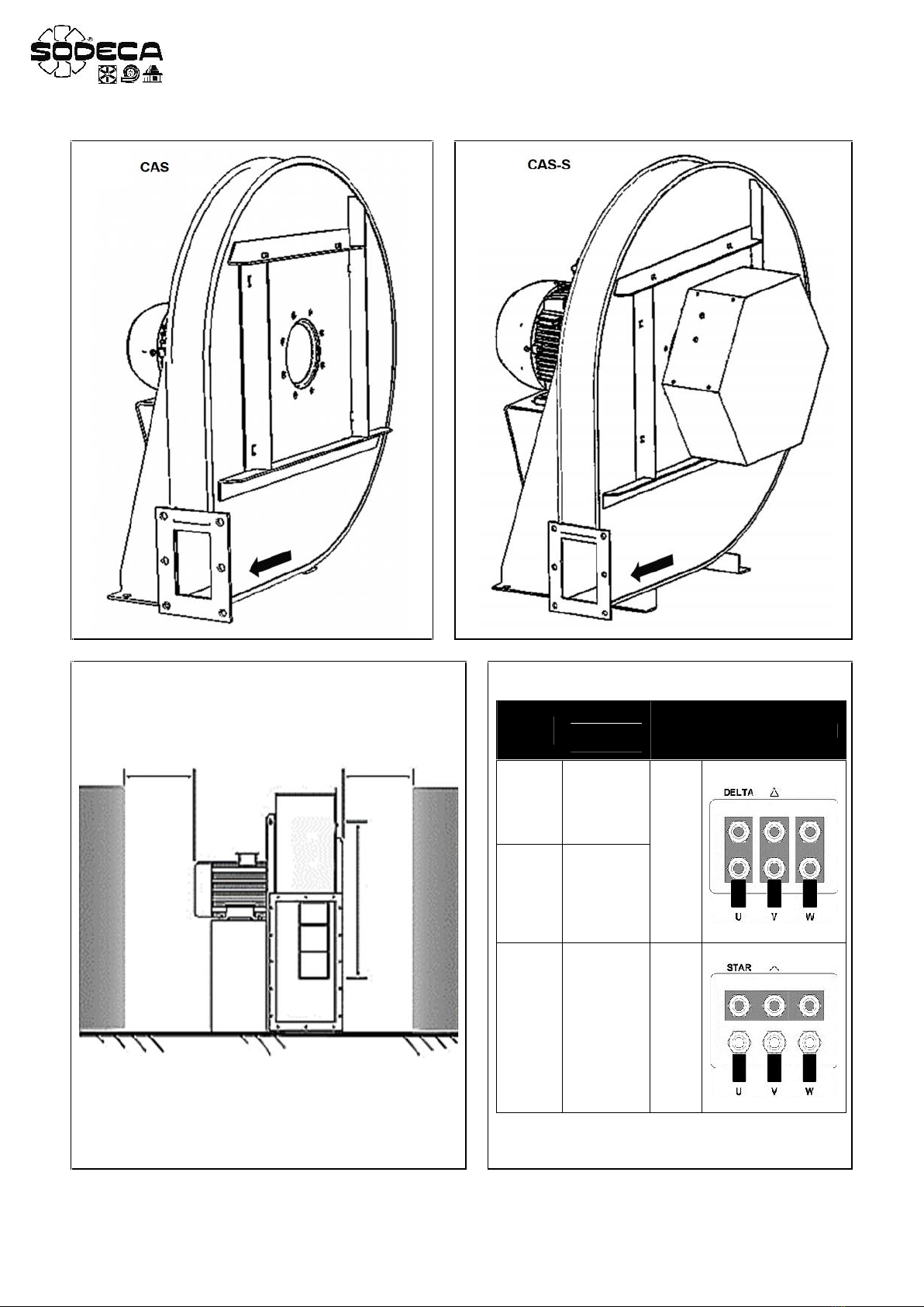
•Podczas podłączania kanałów upewnij się, że kierunek przepływu powietrza jest prawidłowy zgodnie ze
strzałkami wskazującymi kierunek przepływu przez urządzenie (Rys. 1 i 2).
•Instalacje nalezy wykonać w taki sposób, aby ciężar całego systemu nie był przenoszony na urządzenie.
•Nie należy łączyć kolanek w pobliżu kołnierzy lub zacisków urządzenia.
•Jeśli kanały nie zostały zainstalowane po stronie dyszy ssącej, należy zachować wolną odległość równą lub
większą niż średnica D turbiny (Rys. 3).
•Jeśli istnieje możliwość kondensacji wody w urządzeniu, należy podjąć zewnętrzne środki zapobiegawcze.
•Po zakończeniu montażu mechanicznego ważne jest sprawdzenie, czy wirnik obraca się swobodnie, bez tarcia i
naprężeń.
Elektryczne
• Sprawdź, czy urządzenie jest podłączone do źródła zasilania zgodnie z instrukcjami w tym dokumencie (Rys. 4)
i na pokrywie skrzynki przyłączeniowej.
•W celu podłączenia zasilania należy zastosować certyfikowany przewód elektryczny, o odpowiednim przekroju
poprzecznym dla aktualnie uzywanego wentylatora.
DDD%B,)417<$7%.)%*%2323%1/5!.%0/017%7/".)E%.)%.!0)>#)!01<$2),.)+!-/E%"6=56E276.)E5!13/B=
7.!-)/./5!
01!5$7)=#760!1!-%316%,%+316#7.%0/$!.%.!3!",)#7#%7.!-)/./5%*/$0/5)!$!*<7!2),!.)4
'/$.)%7/"/5)<74*<#6-)017%0)2!-)-42)"6=0/$@<#7/.67%5.>317.6%,%-%.3/#(1/..6017%+!C.)+
7!"%70)%#7%.)%-!'.%3/3%1-)#7.%,4""%70)%#7.)+
/417<$7%.)!.!,%E60/$@<#76=47)%-)%.)%
1767!23/2/5!.)423%1/5!.)!01>$+/B#)<2),.)+!.!,%E67!0%5.)=E%2),.)+01!#4*%0/01!5.)%
03$'.,(&-(&
/414#(/-)%.)42),.)+!.!,%E6201!5$7)=#762),.)+/"1!#!2)>01!5)$@/5/"%75)"1!#*),4".)%360/56#(
$C5)>+;5
!,%E6201!5$7)=#7617%#765)2360/";1%.%1'))017%72),.)+.)%017%+1!#7!0/7)/-40/$!.%'/.!%36+)%#)%
417<$7%.)!)#76.)%.!'17%5!2)>.!$-)%1.)%
17<$7%.)%.)%-/E%"6=5@<#7!.%)56@<#7!.%520/2;"017%165!.60/.)%5!E-/E%3/20/5/$/5!=
017%'17!.)%475/*%.)!2),.)+!,4")7/,!#*)
!&0*(1.*$-(&
%15)2417<$7%A-42)"6=56+/.)"*017%756+5!,)&)+/5!.6#(3%#(.)+;5
?/E62+!2<2-!1/5!.%)427#7%,.)/.%.!#!@6#6+,E6#)!)%-.)%**%$.!+7!,%#!.a*%23)#(56-)!.!
#/5'/$7).01!#6,a w przypadku wentylatorów z certyfikatem ATEX co 20.000 godzin pracy.
%B,)5%.36,!3/1.)%*%23560/2!E/.65&),310/5)%317!56-!'!.%*%23#76s7#7%.)%5)1.)+!#/.!*-.)%*1!7
.!27%B=-)%2)>#6
/$#7!2#7627#7%.)!5)1.)+!.!,%E67!#(/5!=/231/E./B=!"6.)%50@65!=.!*%'/565!E%.)%
)%7!,%#!2)>23/2/5!.)!#(%-)#7.6#(B1/$+;5#7627#7<#6#(,4"!'1%265.6#(24"23!.#*)0/.)%5!E-/'<
427+/$7)=417<$7%.)%
01760!$+4+/.)%#7./B#)56-)!.6#7>B#).!,%E62+/.3!+3/5!=2)>7$62316"43/1%-
25+(4$$)$
)%/231/E.!,4".)%$"!@!436,)7!#*!2017>34-/E%0/5/$/5!=7!.)%#7627#7%.)%1/#%24245!.)!/$0!$;5-42)"6=
017%01/5!$7/.67'/$.)%7/"/5)<74*<#6-)5+1!*4./1-!-))017%0)2!-)
*$0$-$)$
)%01!5)$@/5%4E63+/5!.)%417<$7%.)!).)%017%2317%'!.)%)*'*+"*7!5!136#(53%*).2314+#*)-/E%20/5/$/5!=431!3>
'5!1!.#*)

E N
1. S t a r t
All fans produced by SODECA, hereinafter the manufacturer, a n d t h e f u l l l i n e o f a c c e s s o r i e s , h a v e b e e n m a n u f a c t u r e d i n
accordance with the strictest standards in relation toquality assurance, systems and production processes.
T h e i r p r o j e c t , t e s t i n g , m a n u f a c t u r e a n d c o n t r o l s t r u c t u r e h a s b e e n c o n f i g u r e d i n l i n e w i t h E U s t a n d a r d s a n d r e g u l a t i o n s ,
especially in reference to current safety standards.
T h e m a t e r i a l s u s e d i n o u r f a n s , a n d t h e s t a n d a r d i s e d c o m p o n e n t s o f w h i c h t h e y a r e m a d e m e e t t h e s a m e s t a n d a r d s a n d ,
w h e n s o r e q u i r e d , a r e b a c k e d u p b y t h e c o r r e s p o n d i n g q u a l i t y c e r t i f i c a t e s .
T h e O r i g i n a l M a n u a l w a s w r i t t e n i n S p a n i s h .
T h e m a n u f a c t u r e r r e s e r v e s t h e r i g h t t o m a k e m o d i f i c a t i o n s w i t h o u t p r i o r n o t i c e .
All the documentation in this manual is the property of the manufacturer, and its total or partial reproduction is prohibited.
2. P r o d u c t D e f i n i t i o n
C A S : C e n t r i f u g a l s i n g l e - i n l e t , h i g h - p r e s s u r e f a n s w i t h c a s i n g a n d s h e e t s t e e l impeller.
C A S / A T E X : ATEX-certified high pressure single-inlet centrifugal extractor fans.
C A S - S : C e n t r i f u g a l s i n g l e - i n l e t , h i g h - p r e s s u r e f a n s w i t h c a s i n g a n d s h e e t s t e e l i m p e l l e r , w i t h n o i s e r e d u c e r m o u n t e d o n
the fan inlet.
IMPORTANT:
T h i s p r o d u c t i s n o t suitable for use in explosive environmentsor for fire safety.(CAS, CAS-S)
T h i s p r o d u c t i s n o t s u i t a b l e f o r f i r e s a f e t y . (CAS/ATEX)
3. General Information
• Always check the products received.
• After unpacking the equipment, it must be checked to make sure that it is not damaged. D a m a g e d p r o d u c t s m u s t
never be installed.
•T h i s e q u i p m e n t m u s t n o t b e u s e d f o r p u r p o s e s o t h e r t h a n t h o s e f o r w h i c h i t w a s d e s i g n e d ; i t m u s t o n l y o p e r a t e
under the conditions described in this manual.
•In the event of a defect or malfunction, this must be reported to the authorised representative, with a description of
the problem, in order to coordinate its return or possible repair.
• Before starting up the equipment make sure you have read the safety and installation instructions set out in this
document and the“General Specifications for ATEX Fans”attached to the product documentation.(CAS/ATEX)
4. Transportation, storage and handling
• Always hold the equipment at the points provided for this. Do not lift it by the electrical cables, connection boxes,
or the air inlet or outlet.
• Before installation, store the equipment in a clean, dry place, protected from inclement weather.
5. S a f e t y
•D o n o t d i s a s s e m b l e o r m o d i f y t h e e q u i p m e n t . T h i s c o u l d n e g a t i v e l y a f f e c t the equipment or even cause accidents.
•D o n o t p u t y o u r f i n g e r s o r a n y o b j e c t s i n t o t h e p r o t e c t i v e g r i l l e s o n d u c t s , i n l e t s o r o u t l e t s . I f t h i s w e r e t o o c c u r ,
immediately disconnect the equipment's power supply.
•N e v e r u s e a d a m a g e d p o w e r c a b l e .
•D o n o t o p e r a t e t h e e q u i p m e n t i f i t h a s b e e n f o r c i b l y i n s t a l l e d o n a c u r v e d o r u n s t a b l e s u r f a c e .
•D o n o t p e r f o r m e q u i p m e n t i n s p e c t i o n o r m a i n t e n a n c e w i t h o u t f i r s t c h e c k i n g t h e f o l l o w i n g :
oT h a t t h e e q u i p m e n t h a s b e e n d i s c o n n e c t e d f r o m t h e e l e c t r i c a l s u p p l y .
oT h a t a l l its components are at rest.
•T h e e q u i p m e n t m u s t n o t b e o p e r a t e d u n l e s s i t h a s b e e n p r o p e r l y i n s t a l l e d a n d t h e i n l e t a n d o u t l e t h a v e b e e n
protected, if necessary.
In designing and manufacturing the various Series of t h e m a n u f a c t u r e r ' s Fans and Extractors, Hazard Elimination has been
taken into account, in order to meet the conditions for Integrated Safety.
When their configuration and manufacturing processes permit this,the manufacturer directly incorporates the most
appropriate Safety Devices. If the conditions for installation or use mean that these devices cannot be incorporated at source,
all additional safety accessories are available for implementation when the equipment is installed and before it is put into
service.

E N
6. Installation and Assembly
T h i s equipment may only be installed by a qualified technician who is familiar with the installation, monitoring and
maintenance of this type of equipment, and uses suitable tools.
Mechanical
•T o e n s u r e s a f e o p e r a t i o n , t h e e q u i p m e n t m u s t b e f i r m l y f i x e d .
•T h e installation must prevent contact with the fan's impeller through the use of grilles, accessories, or by installing
a connecting tube of a suitable length.
•When connecting the ducts, ensure that the airflow direction is correct in accordance with the arrows indicating
flow direction through the equipment(Fig. 1 and 2).
•T h e i n s t a l l a t i o n m u s t b e s u c h t h a t t h e w e i g h t o f t h e d u c t s y s t e m i s n o t s u p p o r t e d b y t h e e q u i p m e n t .
•D o n o t c o n n e c t t h e e l b o w s c l o s e t o t h e e q u i p m e n t ' s c o n n e c t i n g f l a n g e s o r c l a m p s .
•If the ducts have not been installed on the suction nozzle side, maintain a free distance equal to or greater than
the diameter D of the turbine (Fig. 3).
•If there is a possibility of water condensing in the equipment, external preventive measures must be taken.
•O n c e t h e m e c h a n i c a l a s s e m b l y i s c o m p l e t e , i t i s i m p o r t a n t t o c h e c k t h a t t h e i m p e l l e r t u r n s f r e e l y , w i t h n o f r i c t i o n o r
tension.
E l e c t r i c a l
•C h e c k i f t h e e q u i p m e n t i s c o n n e c t e d t o t h e p o w e r s o u r c e i n a c c o r d a n c e w i t h t h e i n s t r u c t i o n s in this document(Fig.
4), and on the cover of the connection box.
• Select a power cable with a suitable cross-section for the current used by the equipment.
•IMPORTANT:When the equipment is controlled by reducing the voltage, the motor current may be higher than the
rated value.
•C h e c k i f t h e e l e c t r i c a l c h a r a c t e r i s t i c s s t a t e d o n t h e p l a t e c o r r e s p o n d t o t h e p o w e r s u p p l y .
• An external protective component must be connected (a relay, magneto-thermal protection system or fuse), in
accordance with current regulations.
•T h e e q u i p m e n t ' s e a r t h c o n n e c t i o n m u s t b e c o n n e c t e d .
•If the motor speed control is used, it must be guaranteed that the motor will operate correctly.
Start-up
• After starting up the motor, it is important to check that the motor is turning correctly, without vibrations or unusual
noises.
• A check must be made to ensure that the motor's actual power consumption does not exceed the level stated on
the equipment's label and that it does not heat up excessively.
•T h e m a c h i n e m u s t n o t b e s w i t c h e d o n a n d o f f i n t e r m i t t e n t l y , a s t h i s could damage the winding of the motor or the
insulation, due to overheating.
7. Maintenance
M a i n t e n a n c e m u s t b e p e r f o r m e d b y q u a l i f i e d t e c h n i c i a n s .
•T h e b e a r i n g s a r e g r e a s e d a n d s e a l e d f o r l i f e . N e v e r t h e l e s s , c h a n g i n g t h e m a b o u t e v e r y 2 5 . 0 0 0 h o u r s e f f e c t i v e
running time is recommended and 20.000 hours for ATEX models.
•If the fan is not equipped with an air filter, the only maintenance required is to clean the impeller; this must be done
at least once every six months.
•C a r e m u s t b e t a k e n w h e n c l e a n i n g t h e i m p e l l e r , i n o r d e r n o t t o a f f e c t i t s b a l a n c e .
•It is not advisable to use chemical cleaners or aggressive substances, as they could damage the equipment.
•If a part must be replaced, consult the distributor.
8. Disposal
C a r e l e s s o r n e g l i g e n t d i s p o s a l o f t h e e q u i p m e n t m a y c a u s e c o n t a m i n a t i o n . T h e d i s p o s a l p r o c e s s m u s t b e c a r r i e d o u t i n
compliance with the standards and regulations applicable in the country.
9. Warranty
Incorrect use of the equipment and failure to observe the instructions in this manual may result in t h e c a n c e l l a t i o n o f t h e
w a r r a n t y .

SODECA, S.L.U.
Crta. de Berga , Km. 0,7
08580-SANT QUIRZE DE BESORA
(Barcelona – Spain)
Tel. +34 93 8529111
Fax.+34 93 8529042
www.sodeca.com
80-209 Chwaszczyno
ul. Polna 11A
Zapraszamy: pn-pt 8-16
nkontakt
tel.:
tel.kom.: +48 530 753 690
e-mail: [email protected]
web: www.scrol.pl
SODECA W POLSCE
+48 58 661 35 28
+48 58 667 81 92
This manual suits for next models
2
Table of contents
Languages:
Other SODECA Fan manuals

SODECA
SODECA HT User manual

SODECA
SODECA WALL/DUCT User manual

SODECA
SODECA CMP User manual

SODECA
SODECA HGT User manual

SODECA
SODECA THT/WALL-40-2T-1 User manual

SODECA
SODECA HCT/IMP Series User manual

SODECA
SODECA CBDT 9/9-4T User manual

SODECA
SODECA CJBD User manual

SODECA
SODECA CJTHT-40-2/4T-1,5 User manual

SODECA
SODECA KIT BOXPDS User manual

Popular Fan manuals by other brands


Rosenberg
Rosenberg TRE Series Operating instruction

Ribimex
Ribimex PRBAT20/VENSB User and maintenance manual

Carrier
Carrier AIRSTREAM 42BHC Product data

Omega Altise
Omega Altise OAELITEB Operation, maintenance and safety instructions

Ravanson
Ravanson WT-7040SN user manual

Tommy Bahama
Tommy Bahama BAHAMA BREEZES owner's manual