SODECA CBDT 9/9-4T User manual

Code: 1144106
Doc. Num: 0000006457 (2018-07-19)
www.sodeca.com
CBDT
CJBDT
PL
EN
Dokumentacja techniczo-ruchowa
User Manual

Rys. 2
Rys. 3 CJBDT
Rys. 4 CBDT-9/9, 10/10, 12/12, 15/15
Rys. 5 CBDT-18/18, 20/20, 22/22 Rys. 6
Rys. 1

Rys. 7
Rys. 8
Model
Prędkość
(rpm)
Natężenie (A)
Moc
Zainstalowana
(kW)
Max.
przepływ
powietrza
(m
3
/h)
Emitowany poziom
hałasu dB(A)
Waga
(Kg)
230V
400V 690V CJBDT CBDT CJBDT CBDT
CBDT CJBDT 9/9-4T 1420 2,90 1,70 0,55 3000 64 66 44 24
CBDT CJBDT 9/9-4/8T 1440/710
1,76/0,76 0,55/0,15
3000/1750 64/51 66/53 45 25
CBDT CJBDT 9/9-4M 1410 4,10 0,55 3000 64 66 44 23
CBDT CJBDT 9/9-6T 920 1,50 0,90 0,25 2100 60 61 42 22
CBDT CJBDT 9/9-6M 900 2,20 0,25 2100 60 61 42 21
CBDT CJBDT 10/10-4T 1420 2,90 1,70 0,55 3450 67 68 49 26
CBDT CJBDT 10/10-4/8T 1440/710
1,76/0,76 0,55/0,15
3450/1750 67/54 68/55 50 27
CBDT CJBDT 10/10-4M 1410 4,10 0,55 3450 67 68 49 25
CBDT CJBDT 10/10-6T 920 1,50 0,90 0,25 2250 63 64 47 24
CBDT CJBDT 10/10-6M 900 2,20 0,25 2250 63 64 47 23
CBDT CJBDT 12/12-6T-1 940 4,40 2,60 0,75 4800 64 65 69 37
CBDT CJBDT 12/12-6/12T-1 935/430 2,50/1,03 0,75/0,15
4800/2600 64/52 65/53 72 41
CBDT CJBDT 12/12-6M-1 920 5,80 0,75 4800 64 65 69 37
CBDT CJBDT 12/12-6T-1,5 945 6,40 3,70 1,10 6200 65 67 71 39
CBDT CJBDT 12/12-6/12T-1,5 940/450 3,30/1,20 1,10/0,18
6200/3250 65/53 67/55 75 44
CBDT CJBDT 12/12-6M-1,5 920 8,40 1,10 6200 65 67 71 39
CBDT CJBDT 15/15-6T 950 10,30
5,90 2,20 8250 67 68 110 68
CBDT CJBDT 15/15-6/12T 940/470 5,60/2,20 2,20/0,37
8250/4600 67/54 68/55 116 74
CBDT CJBDT 18/18-6T 970 11,00 6,35 4,00 11800 67 69 175 109
CBDT CJBDT 18/18-6/12T 970/480 11,30/4,20 4,00/0,65
11800/6600 67/54 69/56 183 117
CBDT CJBDT 20/20-6T 970 14,00 5,50 14300 68 70 247 151
CBDT CJBDT 20/20-6/12T 970/480 13,70/5,60 5,50/1,00
14300/9700 68/55 70/57 255 159
CBDT CJBDT 22/22-6T 960 18,40 10,60 7,50 18050 69 71 309 190
CBDT CJBDT 22/22-6/12T 970/480 19,00/8,00 7,50/1,40
18050/11800 69/56 71/58 319 200
*Połączenie dla wentylatorówjednofazowych
Zgodnie z ruchem wskazówekzegara
Widziane przez oś
CZARNY NIEBIESKI BRĄZOWY

PL
EN
1.Wstęp
Wszytskie wentylatory produkowane przezfirmęSODECA orazpełna gama akcesoriów, zostały wyprodukowane zgodnie z
najsurowszymi standardami w zakresie zapewnienia jakości, systemów i procesów produkcyjnych. Ichprojekt, konstrukcja,
testy, produkcja i sterowanie zostały skonfigurowane zgodnie zunijnymi normami i regulacjami, zwłaszcza w odniesieniu do
obowiązującychnorm bezpieczeństwa. Materiały stosowane w wentylatorachorazichznormalizowane komponentyy
spełniająte same normy i, jeśli jest to wymagane, sąwspierane odpowiednimi certyfikatami jakości.
Oryginalna instrukcja została napisana w języku hiszpańskim. Producent zastrzega sobie prawo do wprowadzania zmian
bezuprzedniego powiadomienia. Cała dokumentacja w tejinstrukcji jest własnościąproducenta, a jejcałkowite lub
częściowe powielanie jest zabronione.
2. Opis produktu
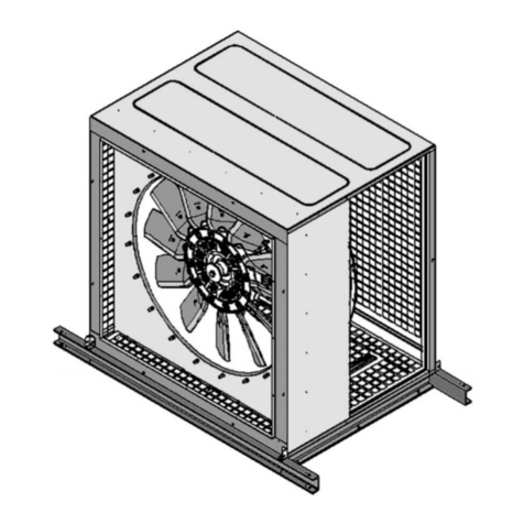
CBDT / CJBDT: Bezpośrednie urządzenie odciągowe, z podwójnym wlotem, do pracy w strefachzagrożonychpożarem
400ºC / 2h i 300ºC / 2h.
WAŻNE: Ten produkt nie nadaje siędo użycia w środowisku zagrożonym wybuchem.
Maksymala temperatura transportowanego powietrza zawiera siępomiędzy -20ºC a +60ºC dla pracy ciągłej, lub 300ºC/2h
oraz 400ºC/2h.
3. Informacje ogólne
• Zawsze sprawdzajotrzymane produkty.
• Po rozpakowaniu urządzenie należy sprawdzić, czy nie jest uszkodzone. Nigdy nie należy instalować
uszkodzonychproduktów.
• Urządzenie nie może byćużywane do celów innychniżte, dla którychzostało zaprojektowane. Musi działaćtylko w
warunkachopisanychw tejdokumentacji.
• W przypadku usterki lubnieprawidłowego działania należy zgłosićsiędo autoryzowanego przedstawiciela wrazz
opisem problemu, w celu koordynacji jego zwrotu lubewentualnejnaprawy.
• Przed uruchomieniem urządzenia należy zapewnić, by zostały przeczytane instrukcje dotyczące bezpieczeństwa i
instalacji zawarte w tym dokumencie.
4. Transport, przechowywanie i obsługa
• Zawsze mocowaćurządzenie w przewidzianychdo tego punktach. Nie podnosićurządzenia za pomocą
przewodów elektrycznych, skrzynekprzyłączeniowych, wlotu powietrza lubwylotu powietrza.
• Przed przystąpieniem do montażu należy przechowywaćurządzenie w czystym, suchym miejscu i chronićje przed
niekorzystnymi warunkami pogodowymi.
5. Bezpieczeństwo
• Nie należy demontowaćani modyfikowaćsprzętu. Może to negatywnie wpłynąć na sprzęt, a nawet powodować
wypadki.
• Nie wkładaćpalców, ani żadnychprzedmiotów w kratki ochronne w kanałach, wlotachlubwylotach. Jeśli taksię
stanie, należy natychmiast odłączyćzasilanie urządzenia.
• Nigdy nie używaćuszkodzonego kabla zasilającego.
• Nie używaćurządzenia, jeśli zostało przymocowane do zakrzywionejlubniestabilnejpowierzchni.
• Nie należy przeprowadzaćkontroli ani konserwacji sprzętu bezsprawdzenia czy:
o Urządzenie zostało odłączone od zasilania elektrycznego, a włącznik
bezpieczeństwa jest zablokowany.
o Wszystkie elementy sąw spoczynku.
• Urządzenia nie można używać, jeśli nie zostało ono prawidłowo zainstalowane, w wloty i wyloty zostały
zabezpieczone, jesli to konieczne.
Przy projektowaniu i produkcji różnychSerii Wentylatorów i Odciągów producenta, w celu spełnienia warunków dla Zin-
tegrowanego Bezpieczeństwa, uwzględniono EliminacjęZagrożeń. Jeśli warunki instalacji lubużytkowania oznaczają, że tych
urządzeńnie można włączyću źródła, wszytskie dodatkowe akcesoria bezpieczeńastwa sądostępne do wdrożenia przed
istalacjąsprzętu i przed oddaniem do eksploatacji.

6. Montażi podłączenie
Wentylatory mogąbyćinstalowanetylkoprzezwykwalifikowanegotechnika,który posiadawiedzęwzakresiemontażu,
przeglądówtechnicznych i konserwacji tegotypuurządzeńoraz korzysta zodpowiednichnarzędzi.
Mec aniczne
• Aby zapewnićbezpiecznąpracę,urządzeniemusi byćodpowiednioitrwalezamocowane.
• Instalacja musi zabezpieczaćprzed kontaktem zwirnikiem.
• Aby otworzyćklapęrewizyjną,należy zapewnićwystarczającąprzestrzeń (Rys. 4 i 5).
• Nie podłączać kolanek blisko kołnierzy przyłączeniowych lub zacisków urządzenia.
• Podczas podłączania przewodów upewnij się, że kierunek przepływu powietrza jest prawidłowy zgodnie ze
strzałkami wskazującymi kierunek przepływu przez urządzenie (Rys. 1 i 2).
• Instalacja musi być taka, aby ciężar systemu kanałów nie był przenoszony na urządzenie.
• Jeśli występujeprawdopodobieństwokondensacji wody w urządzeniu, należypodjąć zewnętrzneśrodki
zapobiegawcze.
• Pozakończeniumontażumechanicznegonależysprawdzić,czy wirnik obracasięswobodnie, beztarcia i
naprężenia.
Elektryczne
• Sprawdź, czy urządzenie jest podłączone do źródła zasilania zgodnie z instrukcjami na pokrywie skrzynki
przyłączeniowej.
• Do podłączenia zasilania elektrycznegotegowentylatora należyużyćspecjalnegokabla certyfikowanegojako
zgodny zprzepisamiprzeciwpożarowymi, o odpowiednimprzekrojudla prądu używanegoprzezwentylator.
• WAŻNE: Gdyurządzeniejest sterowaneprzezzmniejszenienapięcia,prądsilnika możebyćwyższy niżwartość
znamionowa.
• Należysprawdź, czy charakterystyki elektryczne podane na tabliczce odpowiadają zasilaczowi.
• Zewnętrzny element ochronny musi byćpodłączony (przekaźnik,układzabezpieczenia magneto-termicznegolub
bezpiecznik)zgodniezobowiązującymiprzepisami.
• Do urządzenia należypodłączyćuziemienie.
• Jeśli używana jest regulacja prędkościsilnika,należyzagwarantować,żesilnik będziedziałałprawidłowo.
Uruchomienie
• Pouruchomieniusilnika należysprawdźić,czy silnik obracasięprawdiłowo, bezwibracji lubnietypowych
dźwięków.
• Należysprawdzić,czy rzeczywisty pobórenergii przezsilnik nieprzekracza poziomu podanegona etykiecie
urządzenia iczy nienagrzewa sięnadmiernie.
• Urządzenieniemożebyćwłączaneiwyłączanewsposóbprzerywany,ponieważmożetospowodowaćprzegrzanie
uzwojenia silnika lubizolacji.
7. Serwisowanie
Serwis urządzeńmusi byćwykonywany przezwykwalifikowanychtechników.
• Łożyska są nasmarowane i uszczelnione na całe życie. Niemniej jednak, zaleca się zmianę ich co każde 25 000
godzin efektywnego czasu pracy.
• Jeśli wentylatorniejest wyposażony wfiltr powietrza,jedynąkonserwacjąjest czyszczeniewirnika; należytorobić
co najmniejraz na sześć miesięcy.
• Podczas czyszczenia wirnika należyzachowaćostrożność,aby niewpłynąć na jegowyważenie.
• Niezalecasięstosowania chemicznychśrodkówczyszczącychani agresywnychsubstancji,ponieważmogąone
uszkodzićsprzęt.
• Jeśli konieczna jest wymiana części, należyskonsultowaćsięzdystrybutorem.
Dla urządzeńjednofazowych, zsilnikiem 400ºC / 2
• Należy przeprowadzać regularny przegląd co 6 miesięcy.
• Wszystkie czynności wykonywane na silnikach muszą być utrzymywane bez napięcia elektrycznego podczas
instalacji. Upewnij się, że silnik jest odłączony od instalacji elektrycznej.
• Obserwuj zewnętrzną stronę silnika od wentylatora lub instalacji, w której może być zainstalowany. Oczyść silnik z
zewnątrz; Wszelkiego rodzaju gromadzenie się pyłu lub przeszkód, które można znaleźć na skrzydłach i ochra-
niaczach chłodzących musi zostać usunięte.
• Wyczyść wentylator lub urządzenie, w którym zamontowany jest wentylator.
• Sprawdź oporność elektryczną każdej fazy. Zauważ, że musi być taka sama we wszystkich fazach.
• Zdemontować silnik i sprawdzić wzrokowo uzwojenie, upewniając się, że w żadnej jego części nie ma wilgoci ani
skroplin. Izolacja uzwojenia musi być większa niż 10M. Jeśli nie, wyczyść i wysusz uzwojenie stojana.

ES
• Węglowodorowa parafina S.E.G. ROYAL-DIAMOND służy do czyszczenia. Musi być nanoszona pędzlem lub
natryskiwana zgodnie z odpowiednimi normami.
• W normalnych warunkach pracy specjalny smar łożyska ulegnie pewnym przekształceniom, które mogą zmienić
nośność łożyska, a wraz z nim charakterystykę smarowania w razie niebezpieczeństwa. Te właściwości zostaną
osiągnięte, gdy silnik przepracuje 8500 godzin.
• Sprawdź, czy silnik przepracował już ponad 8500 godzin lub, że nie nastąpi to przed następną inspekcją. W przeciwnym
razie łożyska muszą być wymieniane przy użyciu tylko łożysk wysokotemperaturowych z luzem wewnętrznym C3 i
specjalnym smarem BUPONT.
• Aby uniknąć uszkodzeń, demontaż i wymiana łożysk jest dozwolona tylko przy użyciu odpowiednich narzędzi.
• Ponownie zamontuj silnik i ręcznie sprawdź, czy nie ma w nim gumek.
• Silnik powinien pracować przez kilka minut, aby umożliwić rozprowadzenie smaru w łożyskach.
• Zamontuj silnik wentylatora lub konstrukcję, w której ma zostać zmontowany, zgodnie z NORMAMI
BEZPIECZEŃSTWA.
• Podłącz silnik do sieci i sprawdź kierunek obrotów oraz czy pobór prądu (prąd A) jest prawidłowy.
8. Utylizacja
Nieostrożna lub niedbała utylizacja sprzętu może powodowaćzanieczyszczenia. Proces usuwania odpadów musi być
przeprowadzony zgodnie z obowiązującymi w kraju normami i przepisami.
9. Gwarancja
Nieprawidłowe użytkowanie urządzenia i nieprzestrzeganie wytycznych zawartych w tej instrukcji może powodowaćutratę
gwarancji.

EN
1. Start
All fans produced by SODECA, hereinafter the manufacturer, and the full l ine o f acc ess ories, hav e bee n man ufact ured in
accordance with the strictest standards in relation to quality assurance, systems and production processes.
Thei r project, testing, manufacture a nd contr ol structure has been configured in line with EU sta ndar ds a nd r egul atio ns ,
especially in reference to current safety standards.
The materials us ed in our fans, and the sta ndardised components of which th ey a re mad e me et t he s am e st anda rds and,
w he n s o r eq ui r ed , a re b ac k ed u p by t h e c or re s po n di ng q u al i ty c e r t i fi ca te s .
The ri ginal Ma nual was wri tten in Spa nish.
The manufacturer reserves the right to make mod ifications wi thout p rior n otice.
All the documentation in this manual is the property of the manufacturer, and its total or partial reproduction is prohibited.
2. Product Definition
CBDT / CJBDT: Double inlet and direct motor extraction unit for working inside fire danger zones 400ºC/2 and 300ºC/2 .
IMPORTANT: This product is not suitable for use in explosive environments.
The maximu m temp erat ure of air to b e tr ansp orte d is between -20 ºC and +60ºC fo r ongoing use, or 3 00 ºC /2 h and 400ºC/2h.
3. General Information
• Always check the products received.
• After unpacking the equipment, it must be checked to make sure that it is not damaged. Damaged products must
never be installed.
• This equipment must not be used for purposes other than those for which it was designed; it must only operate under
the conditions described in this manual.
• In the event of a defect or malfunction, this must be reported to the authorised representative, with a description of
the problem, in order to coordinate its return or possible repair.
• Before starting up the equipment, it is important to ensure that the safety and installation instructions in this document
have been read.
4. Transportation, storage and andling
• Always hold the equipment at the points provided for this. Do not lift it by the electrical cables, connection boxes, or
the air inlet or outlet.
• Before installation, store the equipment in a clean, dry place, protected from inclement weather.
5. Safety
• Do not disassemble or modify the equipment. This could negatively affect the equipment or even cause accidents.
• Do not put your fingers or any objects into the protective grilles on ducts, inlets or outlets. If this were to occur,
immediately disconnect the equipment's power supply.
• Never use a damaged power cable.
• Do not operate the equipment if it has been forcibly installed on a curved or unstable surface.
• Do not perform equipment inspection or maintenance without first checking the following:
o That the equipment has been disconnected from the electrical supply.
o That all its components are at rest.
• The equipment must not be operated unless it has been properly installed and the inlet and outlet have been
protected, if necessary.
In designing and manufacturing the various Series of the manufacturer's Fans and Extractors, Hazard Elimination has been
taken into account, in order to meet the conditions for Integrated Safety.
When their configuration and manufacturing processes permit this, the manufacturer directly incorporates the most
appropriate Safety Devices. If the conditions for installation or use mean that these devices cannot be incorporated at source,
all additional safety accessories are available for implementation when the equipment is installed and before it is put into
service.

EN
6. Installation and Assembly
This equipment may only be installed by a qualified technician who is familiar with the installation, monitoring and maintenance
of this type of equipment, and uses suitable tools.
Mec anical
• To ensure safe operation, the equipment must be firmly fixed.
• The installation must prevent contact with the fan's impeller through the use of grilles, accessories, or by installing a
connecting tube of a suitable length.
• Sufficient space must be provided for opening the hatch cover (Fig. 4 and 5).
• Do not connect the elbows close to the equipment's connecting flanges or clamps.
• When connecting the ducts, ensure that the airflow direction is correct in accordance with the arrows indicating flow
direction through the equipment (Fig. 1 and 2).
• The installation must be such that the weight of the duct system is not supported by the equipment.
• If there is a possibility of water condensing in the equipment, external preventive measures must be taken.
• nce the mechanical assembly is complete, it is important to check that the impeller turns freely, with no friction or
tension.
Electrical
• Check if the equipment is connected to the power source in accordance with the instructions on the cover of the
connection box.
• For the electrical supply connection for this fan, special cable certified as compliant with fire regulations must be
used, of a suitable cross-section for the current the fan uses.
• IMPORTANT: When the equipment is controlled by reducing the voltage, the motor current may be higher than the
rated value.
• Check if the electrical characteristics stated on the plate correspond to the power supply.
• An external protective component must be connected (a relay, magneto-thermal protection system or fuse), in
accordance with current regulations.
• The equipment's earth connection must be connected.
• If the motor speed control is used, it must be guaranteed that the motor will operate correctly.
Start-up
• After starting up the motor, it is important to check that the motor is turning correctly, without vibrations or unusual
noises.
• A check must be made to ensure that the motor's actual power consumption does not exceed the level stated on the
equipment's label and that it does not heat up excessively.
• The machine must not be switched on and off intermittently, as this could damage the winding of the motor or the
insulation, due to overheating.
7. Maintenance
Maintenance must be performed by qualified technicians.
• The bearings are greased and sealed for life. Nevertheless, changing them about every 25.000 hours effective
running time is recommended.
• If the fan is not equipped with an air filter, the only maintenance required is to clean the impeller; this must be done
at least once every six months.
• Care must be taken when cleaning the impeller, in order not to affect its balance.
• It is not advisable to use chemical cleaners or aggressive substances, as they could damage the equipment.
• If a part must be replaced, consult the distributor.
For products wit single p ase, motor 400ºC / 2
• Make regular inspections each 6 months.
• All manipulations done to the motors must be held with no electrical tension at the installation. Ensure the motor is
disconnected from the electrical system.
• bserve the external side of the motor from the fan or any kind of installation where it might be installed. Clean the
motor externally; all kind of dust accumulation or obstruction, which could be found at the refrigeration wings and
protector, must be taken out.
• Clean the fan or the equipment where the fan is assembled.
• Check the electrical resistance of each phase. Notice it has to be the same in all phase.
• Disassemble the motor and check the winding visually, making sure there is no humidity nor condensation in any
part of it. Winding insulation must be higher than 10MΩ. If not, clean and dry out the stator winding.

EN
• Hydrocarbon paraffin of S.E.G. ROYAL-DIAMOND has be used for cleaning. It must be applied with paintbrush or
sprayed according correspondent application norms.
• In normal work conditions, the bearing’s special grease will suffer certain transformations, which could vary the
bearing’s capacity and with it characteristics of lubrication in case of emergency. These characteristics will be
reached when the motor has worked 8500 hours.
• Check if the motor has already worked more than 8500 hours or that this will not happen before the next inspection.
therwise, bearings have to be replaced using only high temperature bearings with C3 internal clearance and with
BUP NT special grease.
• To avoid damages the bearings’ disassembling and replacing is only allowed when using adequate tools.
• Assemble the motor again and manually check if it tums without any rubbings.
• The motor should work a few minutes to enable the distribution of the grease into the bearings.
• Assemble the motor fan or the application where it should be assembled, granting the SECURITY NRMS.
• Connect the motor to the mains and check the rotation direction and that the power consumption (A current) is
correct.
8. Disposal
Careless or negligent disposal of the equipment may cause contamination. The disposal process must be carried out in
compliance with the standards and regulations applicable in the country.
9. Warranty
Incorrect use of the equipment and failure to observe the instructions in this manual may result in the cancellation of the
w ar r an t y.

SODECA, S.L.U.
Crta. de Berga , Km. 0,7
08580-SANT QUIRZE DE BESORA
(Barcelona –Spain)
Tel. +34 93 8529111
Fax.+34 93 8529042
comercial@sodeca.com
www.sodeca.com
80-209 Chwaszczyno
ul. Polna 11A
Zapraszamy: pn-pt 8-16
nkontakt
tel.:
tel.kom.: +48 530 753 690
e-mail: [email protected]
web: www.scrol.pl
SODECA W POLSCE
+48 58 661 35 28
+48 58 667 81 92
This manual suits for next models
47
Table of contents
Languages:
Other SODECA Fan manuals
SODECA
SODECA CMP User manual
SODECA
SODECA HT User manual
SODECA
SODECA THT/WALL-40-2T-1 User manual
SODECA
SODECA HGT User manual
SODECA
SODECA HCT/IMP Series User manual

SODECA
SODECA WALL/DUCT User manual

SODECA
SODECA CJBD User manual
SODECA
SODECA KIT BOXPDS User manual

SODECA
SODECA CAS User manual
SODECA
SODECA CJTHT-40-2/4T-1,5 User manual
