SODECA HT User manual

C o d e : 1 1 3 4 9 7 3
D o c . N u m : 0 0 0 0 0 0 5 5 2 4 ( 2 0 1 6 - 1 0 - 0 5 )
www.sodeca.com
HT
HT - ATEX
P L
E N
Dokumentacja techniczno ruchowa
U s e r M a n u a l

Rys. 1
Rys. 2
Rys.3
HT - 25…63
HT - 71…100
HT - 25…63
HT - 25…63

Fig. 4
Fig. 5
Rys.6
(Modele 50 Hz)
M o d e l P r ę d k o ś ć
M a x . d o p u s z c z a l n e
n a t ę ż e n i e p r ą d u (A)
M o c
z a i n s t a l o w a n a
M a k s y m a l n y
p r z e p ł w
p o w i e t r z a
P o z i o m c i ś n i e n i a
a k u s t y c z n e g o (dBA)
P r z y b l i ż o n a
w a g a
r/min
230V
400V
600V
(kW)
(m
3 /h)
W l o t
W y l o t
(kg)
HT-25-4T
1320
0,65
0,38
0,09
1080
41
40
12,5
HT-25-4M
1380
0,65
0,10
1080
41
40
12,5
HT-31-4T
1320
0,65
0,38
0,09
1800
47
46
13,3
HT-31-4M
1370
0,83
0,09
1800
47
46
13,5
HT-35-4T
1320
0,65
0,38
0,09
2600
48
47
17,5
HT-35-4M
1370
0,83
0,09
2600
48
47
17,5
HT-40-4T
1350
1,66
0,96
0,25
4600
51
50
21,0
HT-40-4M
1370
2,00
0,25
4600
51
50
21,0
HT-45-4T
1370
2,02
1,17
0,37
6500
55
53
29,0
HT-45-4M
1400
2,76
0,37
6500
55
54
30,5
HT-50-4T
1380
2,92
1,69
0,55
8500
59
57
36,0
HT-50-4M
1350
4,40
0,55
8500
59
57
39,0
HT-56-4T
1410
3,10
1,79
0,75
9800
61
57
35,0
HT-56-4M
1410
5,05
0,75
9800
61
57
37,0
HT-56-6T
900
1,51
0,87
0,25
6600
48
46
46,0
HT-56-6M
900
2,07
0,25
6600
48
46
46,0
HT-63-4T
1400
4,03
2,32
1,10
14000
63
59
65,8
HT-63-6T
900
2,24
1,30
0,37
9200
52
49
61,8
HT-63-6M
900
2,69
0,37
9200
52
49
61,8
HT - 71…100
HT - 71…100

Model
Prędikość
Max. dopuszczalne
natężenie prądu (A)
Max.
przepływ
powietrza
Poziom ciśniena
akustycznego (dBA)
Przybliżona
waga
r/min
230V
400V
600V
(kW)
(m3/h)
Inlet
Outlet
(kg)
HT-71-4T
1430
5,96
3,44
1,50
18000
69
67
64,0
HT-71-6T
900
2,99
1,73
0,55
12200
58
56
64,9
HT-71-6M
900
3,84
0,55
12200
58
56
64,9
HT-80-4T
1445
8,36
4,83
2,20
26200
73
70
87,8
HT-80-6T
945
4,88
2,82
1,10
18000
64
61
81,8
HT-90-4T
1445
10,96
6,33
3,00
31500
77
74
94,0
HT-90-6T
955
6,42
3,71
1,50
21200
68
65
91,0
HT-100-4T-7,5
1440
11,60
6,72
5,50
37000
80
77
114,0
HT-100-4T-10
1455
14,20
8,20
7,50
44000
84
81
125,0
HT-100-6T-2
955
6,42
3,71
1,50
25000
71
68
102,0
HT-100-6T-3
955
9,30
5,30
2,20
28200
75
72
106,0
HT-100-8T-1,5
705
5,63
3,25
1,10
19050
64
61
103,0
HT-100-8T-2
705
7,10
4,10
1,50
21100
66
63
114,0
Rys. 7
(Modele 60 Hz)
Model Prędkość
Max. dopuszczalne
natężenie prądu (A)
Moc
zainstalowana
Max.
przepływ
powietrza
Poziom ciśnienia
akustycznego (dBA)
Przybliżona
waga
r/min
220-277V
380-480V
(kW)
(m3/h)
Inlet
Outlet
(kg)
HT-25-4T
1740
0,65
0,38
0,09
1080
41
40
12,5
HT-25-4M
1740
0,65
0,10
1080
41
40
12,5
HT-31-4T
1716
0,65
0,38
0,09
1800
47
46
13,3
HT-31-4M
1716
0,83
0,09
1800
47
46
13,5
HT-35-4T
1632
0,65
0,38
0,09
2600
48
47
17,5
HT-35-4M
1632
0,83
0,09
2600
48
47
17,5
HT-40-4T
1680
1,66
0,96
0,25
4600
51
50
21
HT-40-4M
1680
2,00
0,25
4600
51
50
21
HT-45-4T
1656
2,02
1,17
0,37
6500
55
53
29
HT-45-4M
1650
2,76
0,37
6500
55
54
30,5
HT-50-4T
1656
2,92
1,69
0,55
8500
59
57
36
HT-50-4M
1620
4,40
0,55
8500
59
57
39
HT-56-4T
1740
3,10
1,79
0,75
9800
61
57
35
HT-56-4M
1740
5,05
0,75
9800
61
57
37
HT-56-6T
1140
1,51
0,87
0,25
6600
48
46
46
HT-56-6M
1140
2,07
0,25
6600
48
46
46
HT-63-4T
1740
4,03
2,32
1,10
14000
63
59
65,8
HT-63-6T
1140
2,24
1,30
0,37
9200
52
49
61,8
HT-63-6M
1140
2,69
0,37
9200
52
49
61,8
HT-71-4T
1740
5,96
3,44
1,50
18000
69
67
64
HT-71-6T
1140
2,99
1,73
0,55
12200
58
56
64,9
HT-71-6M
1140
3,84
0,55
12200
58
56
64,9
HT-80-4T
1740
8,36
4,83
2,20
26200
73
70
87,8
HT-80-6T
1140
4,88
2,82
1,10
18000
64
61
81,8
Moc
zainstalowana

M o d e l
P r ę d k o ś ć
Ma x. dop uszc zaln e
na tę żeni e pr ądu (A)
M o c
z a i n s t a l o w a n a
M a x .
p r z e p ł y w
p o w i e t r z a
P o z i o m c i ś n i e n i a
a k u s t y c z n e g o (dBA)
P r z y b l i ż o n a
w a g a
r/min
220-277V
380-480V
(kW)
(m
3 /h)
Inlet
O u t l e t
(kg)
HT-90-4T
1740
10,96
6,33
3,00
31500
77
74
94
HT-90-6T
1140
6,42
3,71
1,50
21200
68
65
91
HT-100-4T-7,5
1740
11,60
5,50
37000
80
77
114
HT-100-4T-10
1740
13,90
7,50
44000
84
81
125
HT-100-6T-2
1128
6,42
3,71
1,50
25000
71
68
102
HT-100-6T-3
1152
9,30
5,30
2,20
28200
75
72
106
Rys 8
M o d e l
P r ę d k o ś ć
M a x . dopuszczalne
n a t ę ż e n i e p r ą d u (A)
M o c
z a i n s t a l o w a n a
M a x .
p r z e p ł y w
p o w i e t r z a
Poziom ciśnienia
akustycznego(dBA)
P r z y b l i ż o n a
w a g a
r/min
230V
400V
690V
(kW)
(m
3 /h)
Inlet
O u t l e t
(kg)
HT/ATEX-25-4T
1320
0,65
0,38
0,09
1080
41
40
12,5
HT/ATEX-31-4T
1320
0,65
0,38
0,09
1800
47
46
13,3
HT/ATEX-35-4T
1320
0,65
0,38
0,09
2600
48
47
17,5
HT/ATEX-40-4T
1370
2,08
1,20
0,25
4600
51
50
21,0
HT/ATEX-45-4T
1370
2,60
1,50
0,37
6500
55
53
29,0
HT/ATEX-50-4T
1410
2,94
1,70
0,55
8500
59
57
36,0
HT/ATEX-56-4T
1410
3,81
2,20
0,75
9800
61
57
35,0
HT/ATEX-56-6T
910
2,42
1,40
0,25
6600
48
46
46,0
HT/ATEX-63-4T
1410
5,20
3,00
1,10
14000
63
59
65,8
HT/ATEX-63-6T
935
2,77
1,60
0,37
9200
52
49
61,8
HT/ATEX-71-4T
1400
6,93
4,00
1,50
18000
69
67
64,0
HT/ATEX-71-6T
930
3,46
2,00
0,55
12200
58
56
64,9
HT/ATEX-80-4T
1410
9,01
5,20
2,20
26200
73
70
87,8
HT/ATEX-80-6T
910
5,89
3,40
1,10
18000
64
61
81,8
HT/ATEX-90-4T
1440
12,30
7,10
3,00
31500
77
74
94,0
HT/ATEX-90-6T
940
7,62
4,40
1,50
21200
68
65
91,0
HT/ATEX-100-4T-7,5
1440
12,00
6,93
5,50
37000
80
77
114,0
HT/ATEX-100-4T-10
1448
16,30
9,41
7,50
44000
84
81
125,0
HT/ATEX-100-6T-2
940
7,62
4,40
1,50
25000
71
68
102,0
HT/ATEX-100-6T-3
940
9,35
5,40
2,20
28200
75
72
106,0

PL
1. Wstęp
Wszytskie wentylatoryprodukowane przez firmę SODECA oraz pełna gama akcesoriów, zostały wyprodukowane zgodnie z
najsurowszymi standardami w zakresie zapewnienia jakości, systemów i procesów produkcyjnych. Ich projekt, konstrukcja,
testy, produkcja i sterowanie zostały skonfigurowane zgodnie z unijnymi normami i regulacjami, zwłaszcza w odniesieniu
do obowiązująch norm bezpieczeństwa. Materiały stosowane w wentylatorach oraz ich znormalizowane komponenty
spełniają te same normy i jeśli to wymagane, są wspierane odpowiednimi certyfikatami jakości. Oryginalna instrukcja
została napisana w języku hiszpańskim. Producent zastrzega sobie prawo do wprowadzania zmian bez uprzedniego
powiadomienia, Cała dokumentacja w tej instrukcji jest własnością producenta, a jej całkowite lub częściowe powielanie
jest zabronione.
2. Opis produktu
HT: Osiowe wentylatory dachowe z wirnikiem z tworzywa sztucznego wzmocnionego włóknem szklanym, z płaską
podstawą do montażu na dachu.
HT/ATEX: Osiowe wentylatory dachowe z certyfikatem ATEX opcjonalnie z oznaczeniem Ex e. Ex d. Ex tc oraz Ex tb
WAŻNE:
Ten produkct nie nadaje się do użycia w środowisku zagrożonym wybuchem i ochrony przeciwpożarowej .(HT)
Ten produkt nie nadaje się do ochrony przeciwpożarowej. (HT/ATEX)
3. Informacje ogólne
•Zawsze sprawdzaj otrzymane produkty.
•Po rozpakowaniu urządzenia należy sprawdzić, czy nie jest uszkodzone. Nigdy nie należy instalować uszkodzo-
nych produktów.
•Urządzenie nie może być używane do celów innych niż te, do których zostało zaprojektowane. Musi działać tylko w
warunkach opisanych w tej dokumentacji.
•W przypadku usterki lub nieprawidłowego działania należy zgłosić się autoryzowane przedstawiciela wraz z
opisem problemu , w celu koordynacji jego zwrotu lub ewentualnej naprawy.
•Przed uruchomieniem urządzenia należy zapewnić, by zostały przeczytane instrukcje dotyczące bezpieczeństwa i
instalacji zawarte w tym dokumencie oraz Generalnej Specyfikacji dla wentylatorów z certyfikatem ATEX,
dołączonej do dokumentacji produktu.(HT/ATEX)
4. Transport, przechowywanie obsługa
•Zawsze montować urządzenie w przewidzianych do tego punktach (Rys. 2). Nie podnosić go za pomocą
przewodów elektrycznych, skrzynek przyłączeniowych, wlotu lub wylotu powietrza.
•Przed przystąpieniem do montażu należy przechowywać urządzenie w czystym, suchym miejscu i chronić je
przed niekorzystnymi warunkami atmosferycznymi.
5. Bezpieczeństwo
•Nie należy demontować ani modyfikować sprzętu.Może to negatywnie wpłynąć na sprzęt, a nawet powodować
wypadki.
•Nie wkładać palców, ani żadnych przedmiotów w kratki ochronne na kanałach, wlotach lub wylotach. Jeśli tak się
stanie, należy natychmiast odłączyć zasilanie urządzenia.
•Nigdy nie używać uszkodzonego kabla zasilającego.
•Nie używać urządzenia jeśli zostało przymocowane do zakrzywionej lub niestabilnej powierzchni.
•Nie należy przeprowadzać kontroli ani konserwacji sprzętu bez sprawdzenia czy:
oUrządzenie zostało odłączone od zasilania elektrycznego, a włącznik bezpieczeństwa jest zablokowany.
oWszystkie elementy są zablokowane.
•Urządzenia nie można używać, jesli nie zostało ono prawidłowo zainstalowane, a wloty i wyloty zostały
zabezpieczone, jesli to konieczne.
Przy projektowaniu i produkcji różnych Serii Wentylatorów i Odciągów producenta, w celu spełnienia warunków dla
Zintegrowanego Bezpieczeństwa, uwzględniono Eliminację Zagrożeń. Jeśli warunki instalacji lub użytkowania oznaczają,
że tych urządzeń nie nie można włączyć u źródła, wszytskie dodatkowe akcesoria bezpieczeństwa są dostępne do
wdrożenia przed instalacją sprzętu i przed oddaniem do eksploatacji.

PL
6. Montaż i podłączenie
Wentylatory mogą być instalowane ty his equipment may only be installed by a qualified technician who is familiar
with the installation, monitoring and maintenance of this type of equipment, and uses suitable tools.
Mechanical
•To ensure safe operation, the equipment must be firmly fixed.
•The installation must prevent contact with the fan's impeller, through the use of grilles, accessories, or by installing
a connecting tube of a suitable length.
•The fan should be installed so that it does not cause vibration in the ducts or building and to facilitate its
maintenance and cleaning.
•The equipment must be installed in such a way that the whole of its surface area is adhered to the surface on
which it is installed.
•Do not connect the elbows close to the equipment's connecting flanges or clamps
•When connecting the ducts, ensure that the airflow direction is correct in accordance with the arrows indicating
flow direction through the equipment.
•Once the mechanical assembly is complete, it is important to check that the impeller turns freely, with no friction or
tension.
Electrical
•Check if the equipment is connected to the power source in accordance with the instructions on the cover of the
connection box.
• Select a power cable with a suitable cross-section for the current used by the equipment.
•IMPORTANT: When the equipment is controlled by reducing the voltage, the motor's current may be higher than
the rated value.
•Check if the electrical characteristics stated on the plate correspond to the power supply.
• An external protective component must be connected (a relay, magneto-thermal protection system or fuse), in
accordance with current regulations.
•The equipment's earth connection must be connected.
•If the motor speed control is used, it must be guaranteed that the motor will operate correctly.
Start-up
• After starting up the motor, it is important to check that the motor is turning correctly, without vibrations or unusual
noises.
• A check must be made to ensure that the motor's actual power consumption does not exceed the level stated on
the equipment's label and that it does not heat up excessively.
•The machine must not be switched on and off intermittently, as this could damage the winding of the motor or the
insulation, due to overheating.
7. Maintenance
Maintenance must be performed by qualified technicians.
•The bearings are greased and sealed for life. Nevertheless, changing them about every 25.000 hours effective
running time is recommended and 20.000 hours for ATEX models.
•If the fan is not equipped with an air filter, the only maintenance required is to clean the impeller; this must be
done at least once a year.
•Care must be taken when cleaning the impeller, in order not to affect its balance.
•It is not advisable to use chemical cleaners or aggressive substances, as they could damage the equipment.
•If a part must be replaced, consult the distributor.
8. Disposal
Careless or negligent disposal of the equipment may cause contamination. The disposal process must be carried out in
compliance with the standards and regulations applicable in the country.
9. Warranty
Incorrect use of the equipment and failure to observe the instructions in this manual may result in the cancellation of the
warranty.

EN
1. Start
All fans produced by SODECA, hereinafter the manufacturer, and the full line of accessories, have been manufactured in
accordance with the strictest standards in relation to quality assurance, systems and production processes.
Their project, testing, manufacture and control structure has been configured in line with EU standards and regulations,
especially in reference to current safety standards.
The materials used in our fans, and the standardised components of which they are made meet the same standards and,
when so required, are backed up by the corresponding quality certificates.
The Original Manual was written in Spanish.
The manufacturer reserves the right to make modifications without prior notice.
All the documentation in this manual is the property of the manufacturer, and its total or partial reproduction is prohibited.
2. Product Definition
HT: Axial roof fans with plastic fibreglass-reinforced impeller, with flat base for roof mounting.
HT/ATEX: ATEX-certified. roof-mounted axial extractor fans and optional Ex e. Ex d. Ex tc and Ex tb marking
IMPORTANT:
This product is not suitable for use in explosive environments or for fire safety. (HT)
This product is not suitable for fire safety. (HT/ATEX)
3. General Information
• Always check the products received.
• After unpacking the equipment, it must be checked to make sure that it is not damaged. Damaged products must
never be installed.
•This equipment must not be used for purposes other than those for which it was designed; it must only operate
under the conditions described in this manual.
•In the event of a defect or malfunction, this must be reported to the authorised representative, with a description of
the problem, in order to coordinate its return or possible repair.
• Before starting up the equipment make sure you have read the safety and installation instructions set out in this
document and the “General Specifications for ATEX Fans” attached to the product documentation. (HT/ATEX)
4. Transportation, storage and handling
• Always hold the equipment at the points provided for this (Fig. 2). Do not lift it by the electrical cables, connection
boxes, or the air inlet or outlet.
• Before installation, store the equipment in a clean, dry place, protected from inclement weather.
5. Safety
•Do not disassemble or modify the equipment. This could negatively affect the equipment or even cause accidents.
•Do not put your fingers or any objects into the protective grilles on ducts, inlets or outlets. If this were to occur,
immediately disconnect the equipment's power supply.
•Never use a damaged power cable.
•Do not operate the equipment if it has been forcibly installed on a curved or unstable surface.
•Do not perform equipment inspection or maintenance without first checking the following:
oThat the equipment has been disconnected from the electrical supply.
oThat all its components are at rest.
•The equipment must not be operated unless it has been properly installed and the inlets and outlets have been
protected, if necessary.
In designing and manufacturing the various Series of the manufacturer's Fans and Extractors, Hazard Elimination has been
taken into account, in order to meet the conditions for Integrated Safety.
When their configuration and manufacturing processes permit this, the manufacturer directly incorporates the most
appropriate Safety Devices. If the conditions for installation or use mean that these devices cannot be incorporated at
source, all additional safety accessories are available for implementation when the equipment is installed and before it is
put into service.

E N
6. Installation and Assembly
T h i s e q u i p m e n t m a y o n l y b e i n s t a l l e d b y a q u a l i f i e d t e c h n i c i a n w h o i s f a m i l i a r w i t h t h e i n s t a l l a t i o n , m o n i t o r i n g a n d
maintenance of this type of equipment, and uses suitable tools.
Mechanical
•T o e n s u r e s a f e o p e r a t i o n , t h e e q u i p m e n t m u s t bef i r m l y f i x e d .
•T h e i n s t a l l a t i o n m u s t p r e v e n t c o n t a c t w i t h t h e f a n ' s i m p e l l e r , t h r o u g h t h e u s e o f grilles, accessories, or by installing
a connecting tube of a suitable length.
•T h e f a n s h o u l d b e i n s t a l l e d s o t h a t i t d o e s n o t c a u s e v i b r a t i o n i n t h e d u c t s o r b u i l d i n g a n d t o f a c i l i t a t e i t s
maintenance and cleaning.
•T h e e q u i p m e n t m u s t b e i n s t a l l e d i n s u c h a way that the whole of its surface area is adhered to the surface on
w h i c h i t i s i n s t a l l e d .
•D o n o t c o n n e c t t h e e l b o w s c l o s e t o t h e e q u i p m e n t ' s c o n n e c t i n g f l a n g e s o r c l a m p s
•When connecting the ducts, ensure that the airflow direction is correct in accordance with the arrows indicating
flow direction through the equipment.
•O n c e t h e m e c h a n i c a l a s s e m b l y i s c o m p l e t e , i t i s i m p o r t a n t t o c h e c k t h a t t h e i m p e l l e r t u r n s f r e e l y , w i t h n o f r i c t i o n o r
tension.
Electrical
•C h e c k i f t h e e q u i p m e n t i s c o n n e c t e d t o t h e p o w e r source in accordance with the instructionso n t h e c o v e r o f t h e
connection box.
• Select a power cable w i t h a suitable cross-section for the current used by the equipment.
•IMPORTANT: When the equipment is controlled by reducing the voltage, the motor's current may be higher than
the rated value.
•C h e c k i f t h e e l e c t r i c a l c h a r a c t e r i s t i c s s t a t e d o n t h e p l a t e c o r r e s p o n d t o t h e p o w e r s u p p l y .
• An external protective component must be connected (a relay, magneto-thermal protection system or fuse), in
accordance withcurrent regulations.
•T h e e q u i p m e n t ' s e a r t h c o n n e c t i o n m u s t b e c o n n e c t e d .
•If the motor speed control is used, it must be guaranteed that the motor will operate correctly.
Start-up
• After starting up the motor, it is important to check that the motor is turning correctly, without vibrations or unusual
noises.
• A check must be made to ensure that the motor's actual power consumption does not exceed the level stated on
the equipment's label and that it does not heat up excessively.
•T h e m a c h i n e m u s t n o t b e s w i t c h e d o n a n d o f f i n t e r m i t t e n t l y , a s t h i s c o u l d d a m a g e t h e w i n d i n g o f t h e m o t o r o r t h e
insulation, due to overheating.
7. Maintenance
M a i n t e n a n c e m u s t b e p e r f o r m e d b y q u a l i f i e d t e c h n i c i a n s .
•T h e b e a r i n g s a r e g r e a s e d a n d s e a l e d f o r l i f e . N e v e r t h e l e s s , c h a n g i n g them about every 25.000 hours effective
running time is recommended and 20.000 hours for ATEX models.
•If the fan is not equipped with an air filter, the only maintenance required is to clean the impeller; this must be
doneat least oncea y e a r .
•C a r e m u s t b e t a k e n w h e n c l e a n i n g t h e i m p e l l e r , i n o r d e r n o t t o a f f e c t i t s b a l a n c e .
•It is not advisable to use chemical cleaners or aggressive substances, as they could damage the equipment.
•If a part must be replaced, consult the distributor.
8. Disposal
C a r e l e s s o r n e g l i g e n t d i s p o s a l o f t h e e q u i p m e n t m a y c a u s e c o n t a m i n a t i o n . T h e d i s p o s a l p r o c e s s m u s t b e c a r r i e d o u t i n
compliance with the standards and regulations applicable in thec o u n t r y .
9. Warranty
Incorrect use of the equipment and failure to observe the instructions in this manual may result in the cancellation of the
w a r r a n t y .

SODECA, S.L.U.
Crta. de Berga , Km. 0,7
08580-SANT QUIRZE DE BESORA
(Barcelona – Spain)
Tel. +34 93 8529111
Fax.+34 93 8529042
comercial@sodeca.com
www.sodeca.com
80-209 Chwaszczyno
ul. Polna 11A
Zapraszamy: pn-pt 8-16
nkontakt
tel.:
tel.kom.: +48 530 753 690
e-mail: [email protected]
web: www.scrol.pl
SODECA W POLSCE
+48 58 661 35 28
+48 58 667 81 92
This manual suits for next models
53
Table of contents
Languages:
Other SODECA Fan manuals
SODECA
SODECA KIT BOXPDS User manual
SODECA
SODECA HGT User manual
SODECA
SODECA CMP User manual

SODECA
SODECA CAS User manual
SODECA
SODECA CBDT 9/9-4T User manual
SODECA
SODECA CJTHT-40-2/4T-1,5 User manual

SODECA
SODECA WALL/DUCT User manual
SODECA
SODECA HC User manual
SODECA
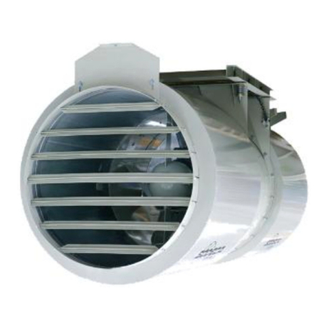
SODECA HCT/IMP Series User manual

SODECA
SODECA CJBD User manual
Popular Fan manuals by other brands

Monte Carlo Fan Company
Monte Carlo Fan Company 3MO52 owner's manual
Ortech
Ortech Compact Series instruction manual
Bimar
Bimar VSL1320 Instruction booklet
Tamarack Technologies
Tamarack Technologies HV1000 Product manual & installation guide

NuAire
NuAire iSense Installation and Maintenance

Stingray
Stingray ALVA Air ACS200 manual
