Soehnle Professional 3035 User manual

www.soehnle-professional.com
Manual
Terminal
3035

2

3
TABLE OF CONTENTS PAGE
1. GENERAL INFORMATION........................................................................................................... 6
1.1 Introduction.......................................................................................................................................... 6
1.2 Intended use ........................................................................................................................................ 6
1.3 Safety instructions............................................................................................................................... 7
1.4 Cleaning ............................................................................................................................................... 7
1.5 Maintenance and service .................................................................................................................... 7
1.6 Product Warranty/liability ................................................................................................................... 8
1.7 Setup instructions................................................................................................................................ 8
2. DEVICE DESCRIPTION ................................................................................................................ 9
2.1 Connection and device description .................................................................................................... 9
2.2 Technical data ..................................................................................................................................... 9
2.3 Symbols on the display ..................................................................................................................... 10
2.4 Calibration instructions..................................................................................................................... 11
2.4.1 Name plate................................................................................................................................. 11
2.4.2 Calibration counter.................................................................................................................... 11
2.5 Switching on / off .............................................................................................................................. 12
3. OPERATING CONCEPT............................................................................................................. 13
3.1 Setting mode...................................................................................................................................... 13
3.2 Program mode................................................................................................................................... 14
3.3 Function keys..................................................................................................................................... 14
4. SETTING MODE......................................................................................................................... 16
4.1 Starting the setting mode.................................................................................................................. 17
4.2 Program settings............................................................................................................................... 18
4.3 Setting mode Terminal settings ....................................................................................................... 19
4.4 Setting mode Scale settings............................................................................................................. 25
4.5 Setting Mode Communication Settings ........................................................................................... 28
4.6 Setting mode Settings Service.......................................................................................................... 39
4.7 Reset Terminal................................................................................................................................... 39
5. BASIC FUNCTIONS ................................................................................................................... 40
5.1 Switching on ...................................................................................................................................... 40
5.2 Switching off...................................................................................................................................... 40
5.3 Program selection ............................................................................................................................. 40
5.4 Zeroing ............................................................................................................................................... 40
5.5 Tare function...................................................................................................................................... 41
5.6 Gross display ..................................................................................................................................... 41
5.7 Scale switching.................................................................................................................................. 41
5.8 Tenfold display x10 ........................................................................................................................... 42
5.9 Hold function ..................................................................................................................................... 43
5.10 Secondary display ........................................................................................................................... 44
5.10.1 Second unit.............................................................................................................................. 46
5.11 Organizational data (identifier)....................................................................................................... 48
5.12 Alphanumeric input ......................................................................................................................... 51
5.13 Key lock............................................................................................................................................ 52
5.14 User Password ................................................................................................................................ 53
5.15 Login function / process start function ......................................................................................... 53
5.16 SD card data backup ....................................................................................................................... 58
5.17 Volume measurement..................................................................................................................... 59
5.18 Dynamic function keys.................................................................................................................... 61
5.18.1 Configuration commands............................................................................................................ 61

4
5.18.2 Defining a dynamic function key ................................................................................................. 61
5.18.3 Switching dynamic function keys on/off .................................................................................... 63
5.18.4 Defining the level of the dynamic function keys......................................................................... 64
5.18.5 Saving the settings of the dynamic function keys ..................................................................... 64
5.18.6 Loading the settings of the dynamic function keys ................................................................... 64
5.18.7 Printing conditions ....................................................................................................................... 65
6 APPLICATION PROGRAMS ....................................................................................................... 66
6.1 Selection of the application programs............................................................................................. 66
6.2 Function keys..................................................................................................................................... 66
6.3 Navigation in the application programs........................................................................................... 67
6.4 Custom programs.............................................................................................................................. 67
6.5 Weighing and taring........................................................................................................................... 68
6.5.1 Function keys............................................................................................................................. 68
6.5.2 Display view ............................................................................................................................... 68
6.5.3 Display information field........................................................................................................... 69
6.5.4 Weighing without taring ............................................................................................................ 70
6.5.5 Manual taring............................................................................................................................. 70
6.5.6 Taring with manual tare ............................................................................................................ 70
6.5.7 Multiplicative tare...................................................................................................................... 71
6.5.8 Additive tare............................................................................................................................... 71
6.5.9 Intermediate tare ....................................................................................................................... 72
6.5.10 Automatic tare......................................................................................................................... 72
6.5.11 Fixed tare value memory......................................................................................................... 73
6.5.12 Error messages when taring................................................................................................... 74
6.5.13 Display options with the Info key............................................................................................ 74
6.5.14 Accepting current values into the fixed memory................................................................... 75
6.5.15 Organizational data (identifier)............................................................................................... 75
6.5.16 Settings in Setting Mode......................................................................................................... 76
6.6 Totalizing and picking ....................................................................................................................... 77
6.6.1 Function keys............................................................................................................................. 77
6.6.2 Display view ............................................................................................................................... 78
6.6.3 Display information field........................................................................................................... 79
6.6.4 Tare function.............................................................................................................................. 80
6.6.5 Operating the totalizing function.............................................................................................. 80
6.6.6 Options for displaying totals..................................................................................................... 81
6.6.7 Relief factor for summation...................................................................................................... 81
6.6.8 Auto-summing / -picking........................................................................................................... 81
6.6.9 Preferred totalizing scale.......................................................................................................... 81
6.6.10 Assigning and deleting the sequence number ...................................................................... 82
6.6.11 Item counter ............................................................................................................................ 82
6.6.12 Keys that trigger printing......................................................................................................... 82
6.6.13 Display of current totals.......................................................................................................... 82
6.6.14 Displaying individual items ..................................................................................................... 83
6.6.15 Display options with the Info key............................................................................................ 84
6.6.16 Accepting current values into the fixed memory................................................................... 84
6.6.17 Organizational data (identifier)............................................................................................... 85
6.6.18 Settings in setting mode ......................................................................................................... 85
6.7 Counting............................................................................................................................................. 87
6.7.1 Function keys............................................................................................................................. 87
6.7.2 Display view Counting ............................................................................................................... 88
6.7.3 Display information field........................................................................................................... 89
6.7.4 Tare function.............................................................................................................................. 89
6.7.5 Counting function...................................................................................................................... 90
6.7.6 Totalizing and picking ............................................................................................................... 92
6.7.7 Reference Statistics .................................................................................................................. 96
6.7.8 Piece control.............................................................................................................................. 97
6.7.9 Counting with several weighbridges ........................................................................................ 98

5
6.7.10 Counting accuracy................................................................................................................... 99
6.7.11 Display options with the Info key..........................................................................................101
6.7.12 Accepting current values into the fixed memory.................................................................101
6.7.13 Organizational data (identifier)............................................................................................. 102
6.7.14 Settings in Setting Mode....................................................................................................... 102
6.8 Checking .......................................................................................................................................... 106
6.8.1 Function keys........................................................................................................................... 106
6.8.2 Display view ............................................................................................................................. 107
6.8.3 Display information field......................................................................................................... 108
6.8.4 Tare function............................................................................................................................ 108
6.8.5 Control functions..................................................................................................................... 108
6.8.6 Totalizing and picking .............................................................................................................111
6.8.7 Display options with the Info key............................................................................................ 115
6.8.8 Saving current values to the fixed memory ...........................................................................115
6.8.9 Organizational data (identifier)...............................................................................................116
6.8.10 Settings in Setting Mode....................................................................................................... 116
7. Error messages....................................................................................................................... 120
8. FURTHER INFORMATION....................................................................................................... 121

6
1. GENERAL INFORMATION
1.1 Introduction
Thank you for choosing the Soehnle Professional Terminal 3035.
This terminal has been developed according to the requirements of operational practice and offers you
numerous possibilities to adapt the weighing process individually to your needs in order to make your
processes rational and cost-effective.
Please read the operating instructions carefully before use.
Improper use could cause damage to you or the terminal.
If you have any questions or if problems arise on your terminal which are not covered in the operating
instructions, please contact your Soehnle Industrial Solutions service center or Soehnle Industrial Solutions
customer service.
Phone: +49 7191 3453-220
Fax: +49 7191 3453-211
E-Mail: [email protected]
Further information and documentation can be found at
https://www.soehnle-professional.com/site/documents
Please go to the customer center of our website www.soehnle-professional.com and select
the terminal 3035 under Downloads.
1.2 Intended use
The Soehnle Professional Terminal 3035 is a calibratable terminal for use in scales and weighing systems
with commercially available DMS weighing and load cells.
Up to three analogue measuring points (scales) can be simultaneously connected internally. Externally, a
total of up to 29 measuring points are possible via CAN bus. Another scale can be connected via the serial
interface, e.g. as a reference scale. Additional data can be entered via the keyboard. Various interface
options are available for the connection of printers, EDP, readers, data memory and external PC keyboard.
The Soehnle Professional Terminal 3035 has been designed for effective working even under rough
environmental conditions. It is robust, easy to clean, flexible and fast. Logical structure and user guidance
enable quick familiarization and intuitive work at the terminal. Its design adapts to your individual
requirements and supports you in your task.

7
1.3 Safety instructions
Before using the device, read the information in the user's manual carefully. They contain important
instructions for the installation, proper use and maintenance of the terminal.
The manufacturer is not liable if the following instructions are not observed:
When using electrical components under increased safety requirements, the relevant regulations must be
observed. Never perform service work on the terminal while it is live. Improper installation will void the
warranty.
> The 3035 terminal must not be used in potentially explosive atmospheres.
A special version is available for EX zones 2 and 22
> The permissible mains voltage is 100 - 240 volts. The socket must be earthed and easily
accessible.
> The terminal must only be opened by trained Soehnle Industrial Solutions service technicians.
The housing contains no user-serviceable components. Unauthorized manipulations render the
product warranty null and void.
> Repairs and the replacement or installation of parts may only be carried out by a trained
Soehnle Industrial Solutions service point.
> The terminal must be taken out of service if the power cable is damaged. Disconnect the power
supply and contact a Soehnle Industrial Solutions service location.
> The attached security labels must not be damaged if the terminal is used for functions with
calibration mandate.
Please contact your Soehnle Industrial Solutions service partner in case of problems.
1.4 Cleaning
A damp cloth and standard cleaning agents are sufficient for cleaning.
Do not use abrasive and corrosive agents.
1.5 Maintenance and service
Note:
These devices comply with the applicable EC directives 2014/31/EU, 2014/30/EU, 2014/35/EU and EN45501.
However, under extreme electrostatic as well as electromagnetic influences, e.g. when operating a radio or
mobile phone in the immediate vicinity of the devices, the scale may be affected.
After the end of the disturbance, the product can be used as intended again,
If necessary, it may be necessary to switch it on again. In case of permanent electrostatic interference we
recommend grounding at the terminal housing and platform.
The terminal is a measuring instrument. Drafts, vibrations, rapid temperature changes and sunlight can affect
the weighing result. The terminal complies with protection class IP 67. Very high humidity, vapors, aggressive
liquids and heavy soiling must be avoided.

8
1.6 Product Warranty/liability
When a defect in the delivered item is attributable to Soehnle Industrial Solutions, Soehnle Industrial
Solutions is entitled at its discretion to either remedy the defect or to supply a replacement. Replaced parts
become the property of Soehnle Industrial Solutions.
The statutory regulations apply if the defect remedy or replacement delivery fails.
The product warranty period begins on the date of purchase. Please retain the invoice as proof. For service
contact your dealer or the Soehnle Industrial Solutions customer service department.
No liability is assumed, in particular for losses resulting for the following reasons:
Unsuited, inappropriate storage or use, defective assembly and/or startup by the buyer or third parties,
normal wear and tear, modifications or manipulations, deficient or careless treatment, in particular excessive
loads, chemical, electrochemical, electrical influences, or moisture, provided these are not attributable to
Soehnle Industrial Solutions.
The product warranty for the unrestricted overall function of the equipment is null and void if operational,
climatic, or other influences result in a significant change of circumstances or the condition of the material.
When Soehnle Industrial Solutions honors the product warranty on a case-by-case basis, this implies the
absence of defects on the delivered item during the product warranty period. Please keep the original
packaging for any required return shipments.
1.7 Setup instructions
Please inspect the packaging and terminal for external damage. Do not place a visibly damaged terminal into
service, but inform your dealer instead.
Please keep the packaging for any required shipping.
The terminal was designed for rough commercial operations. It is nevertheless a sensitive measurement
instrument whose performance can be influenced by unfavorable environmental conditions.
The unit should be acclimated at ambient temperature for 2 hours after unpacking or transport.
The rated ambient temperature is - 10° to + 40° C.
The setup location is a key factor for the function of your scale.
Select an appropriate setup location to protect the terminal against impact, vibration, excessive heat or cold,
temperature swings, airflow, chemicals, and moisture to ensure that the unit can work fast and reliably over
the long-term.

9
2. DEVICE DESCRIPTION
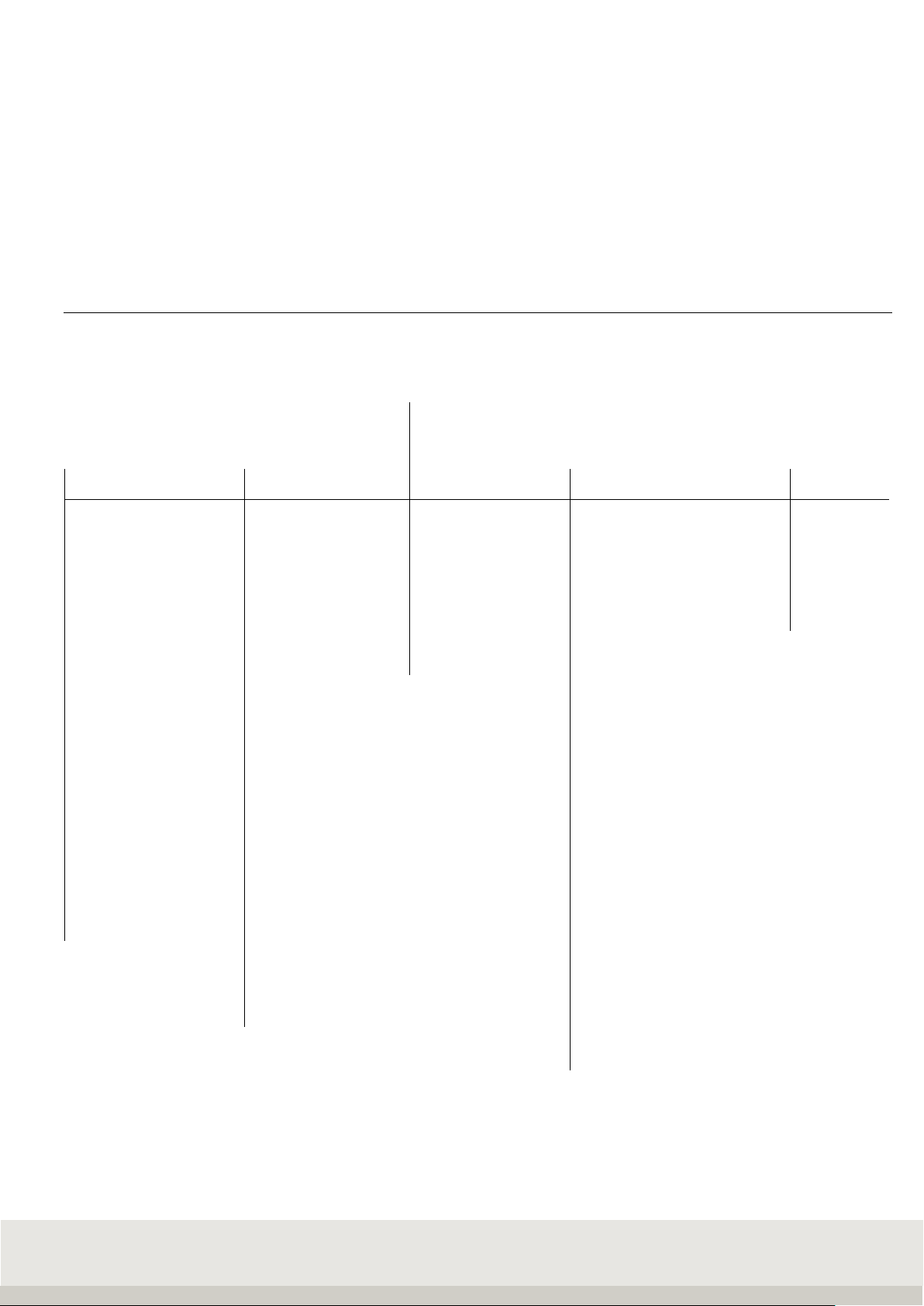
2.1 Connection and device description
2.2 Technical data
> Stainless steel housing, protection class IP 67, integrated power supply 100 - 240 V AC, 50/60 Hz
optional DC/DC-converter 12 - 60 V
> Membrane keyboard with a total of 32 keys, 6 function keys,
4 organization data keys, alphanumeric input via numeric keypad
> 10 user programs, special programs as option
> Connection possibility for external PC keyboard
> color display TFT 5.7" QVGA, dot matrix 320 x 240 pixels dimmable backlighting
> Option: Soehnle Professional Micro-SD card (high-quality SLC memory card), memory capacity:
Fixed memory for a total of 999 fixed values for all programs, alibi memory for 4 million entries
and for software update
> Interfaces: 1 x RS 232 or USB in the basic version.
> Internal with R232, USB and Ethernet, 2 additional interface slots (RS232)
> Any bus slot for bus interfaces such as Profibus, ProfiNet
> Option: IO card for 6 outputs and 4 inputs freely assignable
> Working temperature: -10° C to +40° C
> 1 measuring point in the basic version, 2 further measuring points can be connected internally, in
total up to
29 measuring points, calibratable resolution 10,000 e, internal resolution 16,000,000 d
> Calibratable according to accuracy class III and IIII for n = 10 000 e for multi-range and
multi-partition scales
> Smallest approved input signal per calibrated value = 0.2 µV,
Load cell impedance 40 Ohms to 1,245 Ohm
> A digital reference scale can be connected via RS-232 interface
pressure
compensation
membrane
port
port 1
port 2
scale 1
scale 3
port 3 RS232 / scale 2
power supply
ground
10
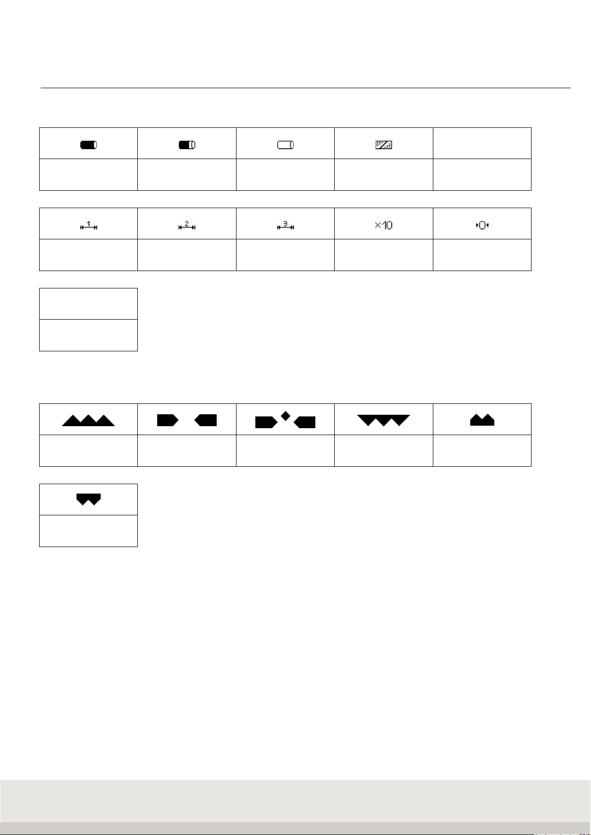
2.3 Symbols on the display
Symbols in the display toolbar
LOG
Alibi memory use
100
Alibi memory use
80
Alibi memory use
empty Keyboard lock Data logger
Multirange 1 Multirange 2 Multirange 3 Resolution X10 Zero
HLD
Hold function active
Symbols in the information field of the display
Below tolerance In tolerance Exact target
value reached Above tolerance Below minimum load
Above class 5
upper limit
Symbol for standstill
After placing the sample on the scale, the scale needs time to settle.
As long as no standstill has occurred, the dimension sign (kg, g) is hidden.
When the machine has come to a standstill and a stable value is available, this is indicated by the display of
the dimension symbol.

11
2.4 Calibration instructions
The scope of this notice is Germany. In other countries, conformity with national laws must be verified.
The Terminal 3035 is approved for custody transfer class III and IIII within the EU.
It complies with the type described in the type approval and the applicable requirements of Directives
2014/31/EU, 2014/30/EU, 2014/35/EU and EN 45501.
According to the legal regulations, approved scales must be recalibrated at regular intervals. For this
purpose, please contact a Soehnle Industrial Solutions service center or your local weights and measures
office.
Do not damage the official seals under any circumstances, as this will invalidate the calibration validity.
2.4.1 Name plate
The terminal has an electronic type plate.
Display after pressing the Info key:
2.4.2 Calibration counter
The calibration counter shows how often a scale has been calibrated. The stored counter reading must
correspond to the calibration counter reading secured by adhesive tape. The current calibration counter
reading can be displayed for each connected scale in the setting mode under Scale / Scale parameters.

12
2.5 Switching on / off
Switch on:
Press the ON/OFF key.
When switching on, the logo , terminal type 3035, filter type and the recognized measuring points are
briefly displayed during the start routine.
The scale is set to zero after the power-on process.
When the machine is switched on, the last application program used is switched back on.
Zero setting limits:
Calibratable: Zero setting range 20% of the weighing range,
Default value is -5% to +15% of the weighing range. Optional: extended range on request.
Non-verifiable: the switch-on zero setting range can be -99% to +99% of the weighing range.
If you switch on outside the switch-on zero setting range, the scale displays an error message.
Afterwards the terminal goes directly into the weighing mode if not verifiable, whereas if verifiable, it is
possible to jump to the weighing mode by pressing the zero key. The current weight value with the
previously stored zero point is then displayed. If the cause for under- or overload is removed, the scale goes
to zero without having to be switched on again and is ready for operation.
Backlight and color
Can be adjusted in the setting mode (terminal/display).
The default setting is 80% for the backlight and white for the background color.
Procedure on power failure
When power is restored, the scale returns to the previously exited state.
Switch off
Press the ON/OFF key .
If the connected measuring point is loaded, or if you have called up a menu, the scale only switches off after
pressing the ON/OFF key for 3 seconds.
It is not possible to switch off the scale while it is waiting for an input in the editing area of the setting mode.
To switch off the scale you must leave the editing area.
OFF display
In the setting mode Service (including password request) / General/OFF display, you can set whether the
word "OFF" appears on the display when the scale is switched off (medical directive).
Default setting is "with OFF display".
13
3. OPERATING CONCEPT
The operating concept is divided into two functional areas:
•Setting mode
•Program mode
3.1 Setting mode
Here you make individual settings on the terminal to optimize the scale for your needs.
Menu structure for setup mode:
Setting mode
Program settings
Terminal
Scale Communication Service
Weighing + taring
Version
Scales Parameters Alibi memory only for
Totalizing and picking
Display
Allocation table
measuring points Interface 1 RS232(internal) Service
Counting
Keypad
Ref. points f. calib. Interface Port 2
Professionals
Checking
Date/Time
internal measuring
point Interface Port 3
Classifiying
Organization data
USB
Recipes
Error memory
Ethernet
Weight conversion
User password
Print image
Vehicle weighbridge
Login function
EDP settings
I/O port programming
Reset Terminal
Anybus
Percentage weighing
SD card
data backup
Barcode
Volume measurement
Batch processing
Dyn. function keys
IO control
IP sensors
14
3.2 Program mode
Here you select the desired weighing application program. After selecting and calling the application
program, the scale is ready to weigh.
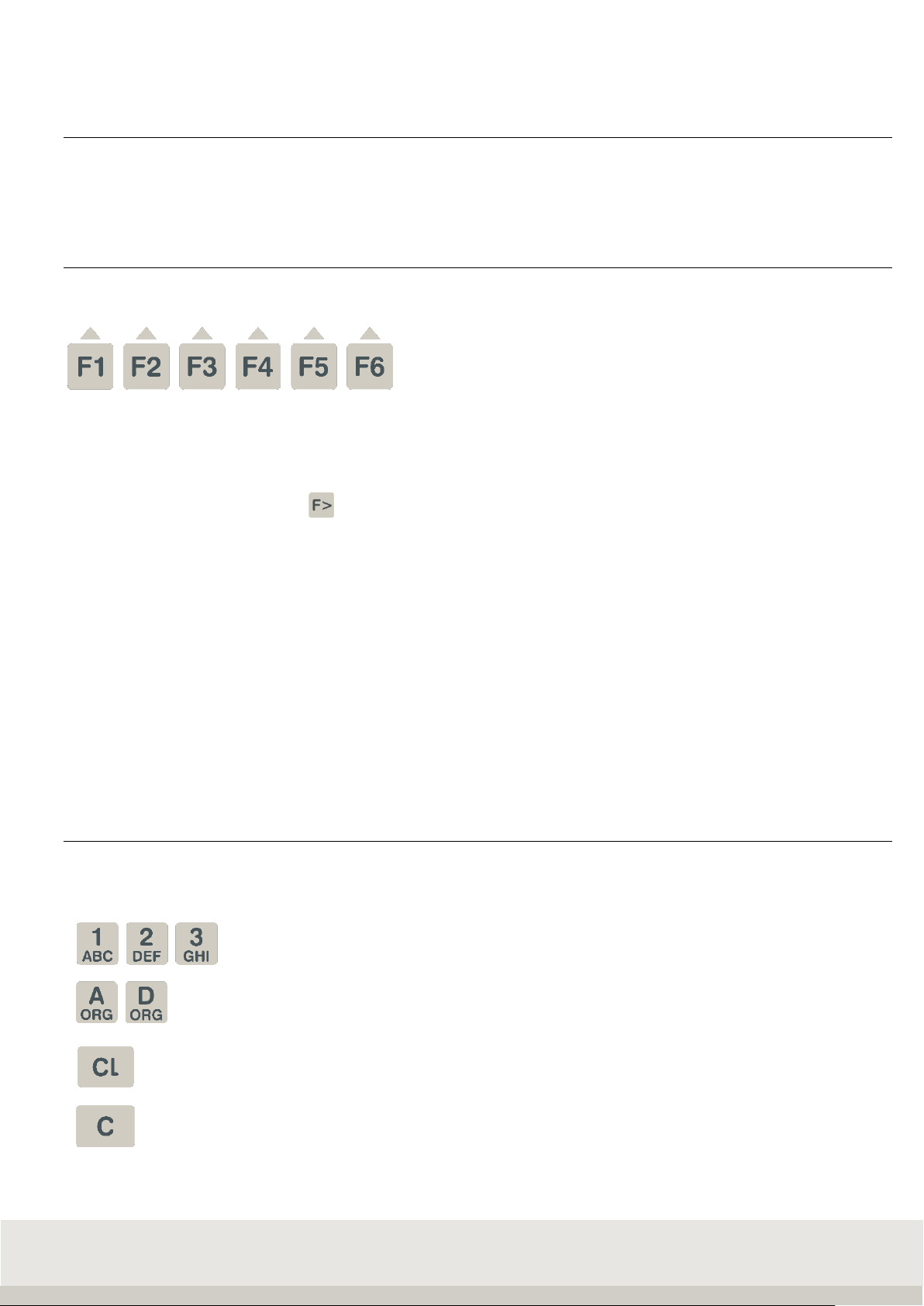
3.3 Function keys
The function keys F1 to F6 are available to call up the functions.
These take on different functions depending on the program and situation. The respective
function is shown on the display in the function bar above the key.
Depending on the program, the function keys are assigned to up to 4 levels, and you can scroll through the
levels with the function change key.
Navigation with the function keys
↑Move the marker up in the list
↓Move the marker down in the list
End Exiting the setting mode
Continue Call up the marked menu item
Back Return to higher level
AbortReturn without accepting a change
Delete Deleting a position with return
ApplyAcceptance of an entry or change
→Cursor to the right
←Cursor to the left
3.4 Input and control keys
The following additional keys are available for input and control:
Numeric keys for entering numerical values,
Multiple assignment of the numeric keys for entering letters
Call up organizational data
Deleting the complete input or resetting the functions
Deleting the last digit

15
Info key, electronic type plate with calibration data,
Calling up information on the application programs
Function change key
Scale change key
Tare key
Reset key / Delete tare
Enter key
Print key
On / Off
Display:
The display shows different views depending on the situation.
It is divided into the following display fields:
FUNKTIONSLEISTE
ANZEIGEFELD
INFORMATIONSFELD
SYMBOLLEISTE
NEBENANZEIGE
BEREICHSANZEIGE
Auxiliary display:
Displays further additional information and can be set individually under Terminal / Display.
Can be switched on and off with the F3 key.
Toolbar:
Shows information on the status of the connected measuring point
Information field:
Shows situation-dependent or individual settings Organizational data, totals when totalizing, special control
characters, classes when classifying, operator guidance, switching points
Display field:
Shows weight value, number of pieces, dimension indicator
Area display:
Displays the current weighing range with Max / Min / e (d).
Function bar:
Functions of the 6 situation-dependent function keys
Aux. display
toolbar
informationfiel
display
range indicator
functionba

16
4. SETTING MODE
In the setting mode, program and weighing parameters are stored, which can be called up and individually set
up.
The adjustment is done by data input or selection from predefined parameters.
The individual parameters are stored in logical groups within a multi-level family tree structure.
Info: The modification options may be restricted in legal metrology.
Menu structure of Setting mode:
Setting mode
Program settings
Terminal
Scale Communication Service
Weighing + taring
Version
Scales Parameters Alibi memory only for
Totalizing and picking
Display
Allocation table
measuring points Interface 1 RS232(internal) Service
Counting
Keypad
Ref. points f. calib. Interface Port 2
Professionals
Checking
Date/Time
internal measuring
point Interface Port 3
Classifiying
Organization data
USB
Recipes
Error memory
Ethernet
Weight conversion
User password
Print image
Vehicle weighbridge
Login function
EDP settings
I/O port programming
Reset Terminal
Anybus
Percentage weighing
SD card
data backup
Barcode
Volume measurement
Batch processing
Dyn. function keys
IO control
IP sensors

17
4.1 Starting the setting mode
Switch on the terminal.
After the switch-on routine, the terminal automatically starts the last activated application program. To call
up the setting mode, switch to the setting functions level with the function change key.
Function keys:
Level Setting functions
Gross x 10 Secondary
display
Prog
ram
Setup
mode
F 1
F 2
F 3
F 4
F 5
F 6
Press the F6 Setting mode key.
You are now in the selection menu Setting mode.
Navigation in setting mode:
The function keys F1 to F6 are available to control the functions.
These take on different functions depending on the program and situation.
The respective function is shown on the display in the function bar.
Meaning of the function keys:
↑Move the marker up in the list
↓Move the marker down in the list
End Exiting the setting mode
Continue Call up the marked menu item
Back Return to higher level
AbortReturn without accepting a change
Delete Deleting a position with return
ApplyAcceptance of an entry or change
→Cursor to the right
←Cursor to the left

18
Entries in setting mode:
In most cases you make a selection from the various settings offered.
For editable values, numeric or alphanumeric input is possible via the keyboard.
Service area:
The service area is secured by a password.
The included parameters can only be maintained by trained service personnel.
Please contact your Soehnle Industrial Solutions service centre.
4.2 Program settings
In the Program Settings setting mode, you can adapt the user programs of your scale to your specific
requirements. The activation of the user programs and their typical use are described in part 6 Application
programs.
1 Weighing and taring
For settings and parameters see chapter 6.5.16
2 Totalizing + picking
For settings and parameters see chapter 6.6.18
3 Counting
For settings and parameters see chapter 6.7.14
4 Controlling
For settings and parameters see chapter 6.8.10
5 Classifying
For settings and parameters see chapter 6.9.10
6 Recipe
For settings and parameters see chapter 6.10.9
7 Neutral measurement
For settings and parameters see chapter 6.11.12
8 Vehicle scale
For settings and parameters see chapter 6.12.9

19
9 Dynamic switching
For settings and parameters see chapter 6.13.11
10 Percentage weighing
For settings and parameters see chapter 6.14.9
4.3 Setting mode Terminal settings
In setting mode under Terminal, you will find the following query or setting options
1 Version
Boot loader software
Software status query
LRS Software AZG
Software status query
Application software AZG
Query software status and filter type
Serial number central board
Requesting the factory-set serial number
Character set
Query character set (in later version as selection):
- Latin 1
Output parameters uni.
Output of all setting parameters of the terminal including the currently connected
measuring point via the interface with the use "EDV 2 (unidirectional)".
2 Display
Backlighting
Input
Luminosity setting, input in percent via numeric keypad
30% is darker, 100% is full brightness
factory setting: 80%
Background colour
Selection
Setting background colour
> green
> white
> light blue
> yellow
> blue
> magenta
> red
Factory setting: white
Language
Selection
1st language German (factory setting)
2nd language English or other languages
can be adapted via the Soehnle Professional service program.
20
2 Display
Secondary display
Selection
> Second unit
> tare value
> x10 resolution
> Gross/net
> Current weight
> reference quantity
> reference weight
> setpoint value
> Difference to setpoint
> Specific weight
> Car registration number
> Weight first/individual weighing
> Traffic light display
> volume
> Sensor connection status
> Last determined. Quantity
Factory setting: Second unit
Decimal Separation
Selection
comma, dot or none
Factory setting: comma
Thousand separator piece
Selection
for separators only for count quantity display
comma, dot or none
Factory setting: None
3 Keyboard
Keypad lock
On the keyboard, you can lock individual, multiple or all keys.
By pressing the key to be locked, you can change the status of the key from open
to locked and vice versa.
Press the Enter key for 3 seconds to save and exit.
Key beep
Selection from or on
Keyboard confirmation beep
Factory setting: off
Receipt beep
Selection from or on
Acknowledgement beep (e.g. error message or acceptance)
Factory setting: off
Keyboard layout
Choice of German or French
Layout for PC - Keyboard layout and keyboard looping via the USB interface
Factory setting: German
Table of contents
Other Soehnle Professional Touch Terminal manuals


