Sofar SPOTTER User manual

User Guide
SPOTTER

SPOTTER

User Guide
SPOTTER

SPOTTER
SPO
4
N
S
W E

What’s Included
Sofar Spotter
Core Features
User Interface
Spotter Measurements
Product Specifications
Safety & Compliance
Getting Started
06
07
08
09
20
22
25
10
Scan the QR code to access
online Support page

6
SPOTTER
What is included in this box?
01 Spotter device
02
5mm hex key to open and close the lid of
the Spotter
Lanyard and magnet to switch from IDLE
to RUN mode
USB-C power charger to charge the
battery prior to deployment
SD card for data storage during
deployment (shipped with unit)
Marine-safe desiccant to reduce
moisture inside the Spotter
Spotter toolkit, including:
Bow shackle for attaching a mooring line

User Guide
7
Spotter is an integrated solution for collecting ocean data. The Spotter
platform consists of a globally-connected Spotter Device (“Spotter”), the
online Spotter Dashboard, and the Spotter Data API.
The Dashboard allows you to congure your Spotter remotely and provides
access to real-time Spotter ocean and tracking data, system status and
alerts, and data visualization.
Sofar Spotter
CORE SYSTEM FEATURES
2-Way Communication Remotely change settings on Spotter through
the online Dashboard.
Alerts + Notifications Set watch perimeter and receive alerts when
Spotter moves outside of it.
Spotter API Access Spotter via our API for seamless
application integration.
Track Mode Fast positional updates for tracking Spotter
through the Dashboard.

8
SPOTTER
MARINE GRADE MATERIALS
The Spotter device is a compact and lightweight instrument consisting of
a waterproof hull, solar panel array, and electronics package.
The Spotter is completely solar-powered so you don’t have to replace or
recharge the battery during deployment. The solar-battery power system is
designed to support Spotter at higher latitudes in limited light conditions.
Core Features
VISIBILITY LIGHT
Flashes amber for nighttime
visibility
TRANSPARENT LID
LEDs provide clear visual
indication of system status,
and can be removed
to access electronics
enclosure and SD card
CAPTIVE LID SCREWS
5mm hex - will not get lost
when lid is removed
HARDWARE INTERFACE
Integrated bottom
attachment point
SURFACE
Use a magnet to switch
modes without opening
the unit and risking water
intrusion
For mooring applications see p. 16
User Guide
9
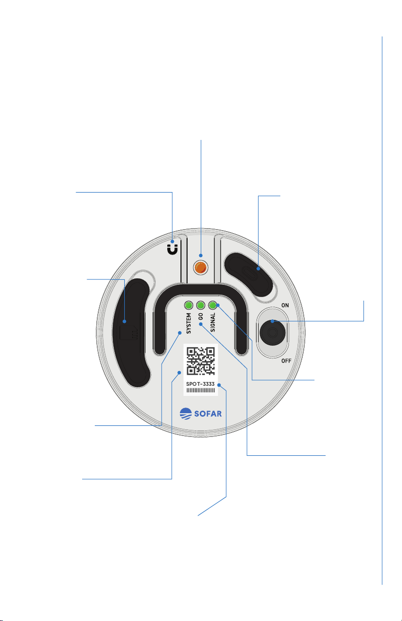
User Interface
GO LED
Displays status of GPS
connectivity and solar
charging system
SIGNAL LED
Indicates whether
a cellular network is
present
USB-C
Charger and data
transfer
ON/OFF
switch
SD CARD
Cover provides
retention
and splash
protection
SPOTTER ID #
MAGNET
Hold here for 3
seconds to switch
between IDLE and
RUN modes
QR CODE
Scan for quick access
to Spotter Dashboard
SYSTEM LED
Communicates system
health status
VISIBILITY LIGHT
SPOT-3333

10
SPOTTER
Getting Started
STEP 01 Set up your account and Spotter
STEP 02 Set up Spotter device
STEP 03 Deploy Spotter in the water
STEP 04 Check your Spotter Dashboard
STEP 05 Retrieve and store Spotter
p. 11
p. 12
p. 16
p. 17
p. 18

User Guide
11
Set up your account and Spotter
Set up user account
Visit spotter.sofarocean.com to set up your user account. Click “Create an
account,” enter personal details, and click “Register.” This will take you to
the overview page.
Register your Spotter
To register your Spotter, click and then “Register Spotter.”
Enter the Spotter ID number and your Activation code, which you should
have received by email from the Sofar team. If you have not received this,
or do not have this available anymore, please contact Sofar at:
The Spotter ID number is also listed on the device, and looks like
SPOT-######. After entering this information, click “Register.”
You will now see your Spotter listed on the overview page. The map will
be updated as soon as the rst data message is received, which typically
takes 1-1.5 hrs from device power on. Please note that message and data
transmission require a clear view of the sky with minimal obstruction in
order to communicate with satellites effectively
STEP 01
11

12
SPOTTER
Ready to go
The Spotter device is completely self-powered and can be operated right
out of the box.
Check the SD card
When inserting or checking the SD card, please make sure the card is
properly seated. The SYSTEM LED will turn red if the card is not seated
correctly.
Turn Spotter on
Switch the on/off switch to the “on” position to turn Spotter on. During
boot-up, the SYSTEM and GO LEDs will be orange, and after startup
they will switch to green. The Spotter device has two possible operating
modes: IDLE mode and RUN mode. You can switch between modes using
the provided magnet by holding it at the designated area for 3 seconds.
The Spotter device will always boot into the last mode it was in before it
was switched off.
Set up Spotter device
STEP 02
MAGNET
Hold here for 3 seconds to
switch between IDLE and
RUN modes

User Guide
13
IDLE RUN
In IDLE mode, the SYSTEM and GO LEDs
alternate ashing green and the visibility
light will be OFF.
In RUN mode, the SYSTEM and GO LEDs
are solid green and the amber visibility light
ashes periodically.
IDLE mode is to save power and suspend
data acquisition and transmission. That
way, you can switch to RUN mode without
having to open the lid.
Use IDLE mode for short-term inactivity, in
preparation for deployment (e.g. transport
to deployment site).
RUN mode is for full system functionality,
including: data acquisition, processing,
data transmission, and onboard logging to
SD card.
Use RUN mode during deployment.
Note: Spotter DOES NOT collect data when in IDLE mode.
Important
• Spotter needs to be switched into RUN mode for deployment.
• If Spotter is in IDLE mode, you can switch to RUN mode by holding a
magnet onto the recessed area directly on top of the electronics box
until the lights turn off. Or, if the transparent lid is screwed on, hold
the magnet onto the recessed round area in the lid for 3 seconds.
• The ashing pattern of the the SYSTEM and GO LEDs and the visibili-
ty light will reveal which mode Spotter is in. (See next pages.)
• In IDLE mode, the SYSTEM and GO LEDs will shut off after 3 minutes
to save power.
When switched to RUN mode, the SYSTEM and GO LEDs communicate
system status and signal when the Spotter is ready to deploy.
SYSTEM LED
Communicates system health status
GO LED
Displays status of GPS connectivity and solar charging system
SIGNAL LED
Indicates whether a cellular network is present

14
SPOTTER
Explanation of user LEDs
CHARGING mode
Both solid green. System is fully charged.
While OFF and connected to a DC charger Spotters light’s will indicate the
following charge status. Please note that charging the Spotter can take
as long as 8 hours.
SYSTEM and GO LEDs Blinking green in sync. System
is charging.
Both solid red. Battery error, battery is not connected.
Both blinking red. Charging error, device is connected
to DC power but not charging properly.
IDLE mode
Both solid orange. System is booting up and running
self-check.
SYSTEM GO At Startup
Blinking green. The system is in IDLE mode. Flashes
in alternating pattern between LEDs for 3 minutes and
then turns off.
After Startup
RUN mode
Both solid orange. System is booting up and running
self-check.
SYSTEM GO At Startup
Both solid green. All systems are checked and OK.
Ready to deploy. Both LEDs will time out after 60
minutes to save power.
After Startup

User Guide
15
RUN mode (continued)
Connectivity
SYSTEM
SYSTEM
GO
GO
SIGNAL
Solid red SYSTEM LED. Check SD card is present. If
not, turn off system, insert a freshly formatted SD card,
and switch back on. If the red light persists, there may
be a serious system error. Do not deploy until this is
resolved, please contact the Sofar team.
Solid red GO LED. Limited GPS connectivity. Ensure
system is outside with a clear view of the sky. Wait
a few minutes for system to connect with the GPS
satellite. If the system has a clear view of the sky and
the GO LED remains red for longer than 30 minutes,
something may be wrong. Please contact the Sofar
team.
All Solid Green.
Cellular data is available; ready to deploy.
Solid red SIGNAL LED.
Cellular data is not available; if deployed,
unit will still be able to use Iridium.
Both solid red. Do not deploy. Follow instructions for
red SYSTEM or GO LED detailed above.
Blinking green GO LED. System is not solar charging.
If this is a night deployment or the panels are covered
ignore and deploy. If this is a day deployment,
something is wrong with the charging system. Do not
deploy.
After Startup (continued)

16
SPOTTER
Activate Spotter in RUN mode
Switch Spotter ON and ensure Spotter is in RUN mode. Ensure both SYSTEM
and GO LEDs are green after ~10 minutes with a clear view of the sky.
Please note that the SYSTEM and GO LEDs time out after 60 minutes to
save power. After 60 minutes you can see that the system is in RUN mode
from the ashing of the visibility light.
Carefully secure lid
Secure the lid using a 5 mm hex key and hand-tighten the 5 captive screws
(with washers) using a star pattern. The captive screws will bottom out to
prevent over-tightening.
Note on mooring design: Sofar Spotter can be deployed either as a free-
oating drifter or in a moored conguration. For free-oating deployments,
the Spotter device comes with everything required to deploy. For moored
applications, you will need to design a mooring to anchor the Spotter
to the seaoor. Visit www.sofarocean.com/posts/spotter-product-
documentation and navigate to “Spotter Mooring Guidelines” for more
information.
Deploy Spotter in the water
STEP 03

User Guide
17
Log in to your account
Visit spotter.sofarocean.com to log in to your user account. Once you are
logged in you are on the overview page. If your Spotter has been deployed,
it will display as a pulsing dot on the map. In that case, Spotter is set up
properly and you can access your data.
Currently the dashboard allows you to:
• View real-time surface wave data from your Spotter.
• Search and download historical data for a custom date range.
• Track your Spotter on the map so you can plot and estimate surface
currents or anticipate a retrieval strategy.
• Set a geofence so you are notied when the Spotter detaches from
its mooring or otherwise moves outside the set boundaries.
• Remotely switch the Spotter into WAVES or TRACK mode. See the
“Spotter Measurements” section on page 20 to determine which
mode you need for your application.
• Access our API to integrate ocean data into your own applications.
• Review health status of your Spotter (battery, system status) and get
notied when something is off.
• Check and renew your data subscription.
• Change your personal prole.
Besides the features described above, we are constantly developing new
functionality for Spotter, so keep an eye on the Spotter dashboard for the
latest news and updates.
Note: Instructions for the dashboard were included in the email that you
received with your activation code. Please see the Spotter Dashboard
Video Guide for how to access the features described above.
Check your Spotter Dashboard
STEP 04

18
SPOTTER
Retrieve the Spotter
After retrieval, disconnect the mooring and rinse off Spotter and mooring
with fresh water before storage. If any fouling has built up on the Spotter,
this can generally be removed with a soft brush and soapy water.
Turn the device o for storage
After rinsing, dry the area around the lid, and unscrew the lid using the 5mm
hex key. Remove the lid carefully to prevent water from dropping onto the
electronics box. After the lid is removed, turn the device off using the on/
off switch. At this point you can also remove the SD card and download
the data stored on the card to your personal computer.
If you plan to store Spotter for a longer period of time, please see the notes
on “Lithium-ion battery use and storage” below.
If you plan to deploy after a prolonged storage period, we recommend
that you use the wall charger provided to fully charge the Spotter before
deployment. This ensures that the system can start up and operate
without delay. Before redeployment, we also recommend that you replace
the desiccant inside the Ebox and use a freshly formatted SD card.
Lithium-ion battery use and storage
Spotter units are equipped with a lithium-ion battery pack, which is located
inside the electronics box. It is important to handle the Spotter device
with care to prevent any possible damage to the electronics and battery
pack. For prolonged storage (longer than a week), the Spotter device
should ideally be stored in a cool (< 25C) and dry area with the battery at
a medium charge.
Retrieve and store Spotter
STEP 05

User Guide
19
Lithium-ion battery packs stored at or near full charge for extended
periods of time can experience a reduction in battery capacity. Therefore,
if planning to store for longer than 1 week, we advise that the battery not
be fully charged. One way to ensure proper state of battery charge is to
run the system for two days without solar power (in a box or dark room)
before turning it off and putting it in storage.
Avoiding submersion of Spotter
Spotter is not rated for continuous submersion. Possible causes of
continuous submersion include:
• Excessive biofouling accumulation on the Spotter or mooring lines.
• A Spotter moored directly in the surf zone or in a way where it is
pulled through the face of a breaking wave.
• Moorings with too much drag or that are missing the required
surface oat(s) recommended in the mooring guidelines.
• Moorings that are incompatible with site-specic ocean conditions,
such as waves and currents.
Please see the Support section of our website for the latest guidelines on
mooring and maintaining your Spotter:
www.sofarocean.com/posts/spotter-product-documentation

20
SPOTTER
Spotter has several modes that can be set remotely through the online
Dashboard. Waves:Standard is the default mode and will likely be the
mode that is used most of the time. In Track mode, the system will provide
faster position updates (e.g. for retrieval), but no wave data. Spotter
modes can be changed and further customized to t various applications.
To learn more about the different modes and how to enable them visit
www.sofarocean.com/posts/spotter-data-modes
Waves:Standard mode
Recommended for standard marine monitoring applications. Wave
displacement data is collected continuously at 2.5Hz. Every 30-minutes,
the system computes the complete cross-spectral matrix and estimates
bulk statistics. To save transmission bandwidth, two time-stamped 30
minute updates of bulk statistics are transmitted every hour.
The Waves:Standard message payload consists of:
• Time (epoch)
• Position (latitude and longitude)
• Signicant Wave Height - estimated from zeroth-order moment of
wave spectrum (Hm0)
• Peak Period - period associated with peak of the wave spectrum (Tp)
• Peak Direction - mean direction at peak of spectrum
• Peak Directional Spread - directional spreading at peak of spectrum
• Mean Period - variance-weighted mean period (Tm01)
• Mean Direction - variance-weighted mean direction
• Mean Directional spread - variance-weighted mean directional spread
All bulk statistics are computed over frequency range 0.03 – 0.8Hz.
For denitions of various bulk wave statistics see e.g. Holthuijsen (2007).
Spotter Measurements
Other manuals for SPOTTER
1
Table of contents
Other Sofar Marine Equipment manuals


