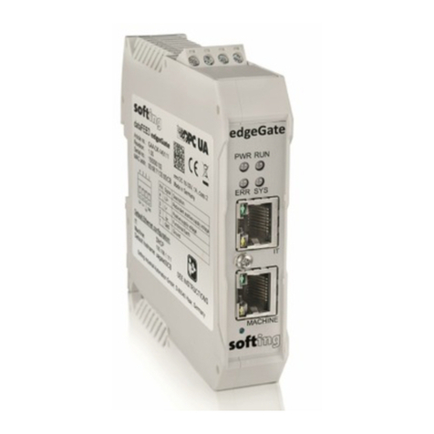
Softing TH LINK User manual

© Copyright 2014 - 2017 Softing Industrial Automation GmbH
TH LINK Industrial Ethernet
TH LINK PROFINET
TH LINK EtherNet/IP
TH LINK Modbus TCP
Installation Manual
Version: EN-062017-4.10

The information contained in these instructions corresponds to the technical status at the time of printing of it and is passed on with the
best of our knowledge. The information in these instructions is in no event a basis for warranty claims or contractual agreements
concerning the described products, and may especially not be deemed as warranty concerning the quality and durability pursuant to Sec.
443 German Civil Code. We reserve the right to make any alterations or improvements to these instructions without prior notice. The
actual design of products may deviate from the information contained in the instructions if technical alterations and product improvements
so require.
It may not, in part or in its entirety, be reproduced, copied, or transferred into electronic media.
Disclaimer of liability
Softing Industrial Automation GmbH
Richard-Reitzner-Allee 6
85540 Haar / Germany
http://industrial.softing.com
The latest version of this manual is available in the Softing download area at: http://industrial.softing.com/en/downloads.html
+ 49 89 4 56 56-0
+ 49 89 4 56 56-488
info.automation@softing.com
support.aut[email protected]

Copyright 2017 Softing Industrial Automation GmbH 3
Table of Contents
Table of Contents
Chapter 1 ............................................................................................ 5
Introduction
...................................................................................................................... 5
1.1 About TH LINK
...................................................................................................................... 5
1.2 Before you connect TH LINK
Chapter 2 ............................................................................................ 6
TH LINK design
...................................................................................................................... 6
2.1 Start-up guideline
...................................................................................................................... 6
2.2 Connections and display elements
...................................................................................................................... 8
2.3 Mount device
...................................................................................................................... 9
2.4 Connect to network
...................................................................................................................... 9
2.5 Connecting power supply and relay contact
Chapter 3 ............................................................................................ 10
Configuring the device in the network
...................................................................................................................... 10
3.1 Configuration requirements
...................................................................................................................... 10
3.2 Network presettings
...................................................................................................................... 11
3.3 Web access and login
...................................................................................................................... 11
3.4 Network overview
...................................................................................................................... 12
3.5 Setting new IP and network address
...................................................................................................................... 13
3.6 Check the connection to the device
...................................................................................................................... 13
3.7 Firmware update
Chapter 4 ............................................................................................ 14
Troubleshooting
Chapter 5 ............................................................................................ 15
Technical Data


Chapter 1 - Introduction
Copyright 2017 Softing Industrial Automation GmbH 5
1Introduction
1.1 About TH LINK
TH LINK provides a secure access to the fieldbus network and forms the basis for the Softing
product TH SCOPE.
Intended use: The TH LINK is designed to be used as a secure access point to Industrial Ethernet
networks. Any other use is deemed non-intended use.
1.2 Before you connect TH LINK
Strictly observe the following safety instructions before connecting the TH LINK:
Note
Small objects or liquids must not enter the case of the TH LINK (e.g. through the ventilation
slots). This may damage the device. Never cover the ventilation slots on the device.
Note
Never open the case of the TH LINK or carry out any mechanical modifications on the
device. This may lead to damages on the device as well as to loss of warranty.
EMC note
The TH LINK contains electronic components sensitive to electrostatic discharges. Damages
due to electrostatic discharge can lead to premature failure of components or intermittent
faults at a later stage. Before installing the TH LINK, divert the electrostatic discharge away
from your body and the tools used.
The TH LINK may only be installed or uninstalled by qualified, trained electrical engineering
personnel. When installing the TH LINK, observe the regulations for handling electric components in
accordance with VDE 0100. In addition, you must also observe the valid safety and accident
prevention regulations (UVV) when operating the device within the jurisdiction of the Federal
Republic of Germany.
High temperature differences between the storage site and installation site can result in
condensation within the case, which may cause the TH LINK to become damaged. In case of high
temperature differences, wait at least three hours before operating the device.
WEEE
Electrical and electronic equipment must be disposed of separately from normal waste
at the end of its operational lifetime.
Please dispose of this product according to the respective national regulations or
contractual agreements. If there are any further questions concerning the disposal of
this product, please contact Softing Industrial Automation.

TH LINK Industrial Ethernet - Installation Manual
6Copyright 2017 Softing Industrial Automation GmbH
2TH LINK design
2.1 Start-up guideline
The following steps are required for start-up:
1. Mounting
2. Plug-in SD card (recommended).
3. Connect to network (see Connect to network).
4. Connect to the power supply (see Connecting the power supply).
5. Configure network (see Configure the device in the network).
2.2 Connections and display elements
Figure 1: TH LINK (front and lateral view)
[1] Ethernet interface for office network
olights yellow: Ethernet data communication
olights green: physical connection available

Chapter 2 - TH LINK design
Copyright 2017 Softing Industrial Automation GmbH 7
[2] LED ETH
olights red: boot procedure
olights green: firmware update in progress
ois off: boot procedure is completed
[3] LED RUN
olights red: internal error
olights green: power supply is applied
ois off: device is not powered
[4] LED BUS
olights red: relay contact active (error occurred in the bus)
olights green: TH SCOPE measurement is running
ois off: TH SCOPE measurement is stopped
[5] Ethernet interface for automation network
olights yellow: Ethernet data communication
olights green: physical connection available
[6] Terminal strip for +24 V DC power supply
oA: 24 V (+)
oB: 0 V (-)
oC: Relay contact - input
oD: Relay contact - output
oE: Protective earth
[7] SD card slot
oYou can save data on the SD card to have the data available even after voltage recovery.
oInsert the SD card before installing the device or putting it into operation. Thus you make sure
the card is recognized during boot procedure.
oNow go to TH LINK Settings TH SCOPE and set the parameter Data restore after voltage
recovery to Yes.
oFollowing the initial device commissioning the SD card is formatted automatically. From this
time on you can save data independently from power interruptions.
Note
If the SD card is not recognized during boot procedure, restart the TH LINK.
[8] Type label

TH LINK Industrial Ethernet - Installation Manual
8Copyright 2017 Softing Industrial Automation GmbH
2.3 Mount device
Note
Make sure you have a minimum of 5 cm below and above the TH LINK in order to ensure
heat dissipation.
Figure 2: Mount and unmount the TH LINK
[1] Device with notch on DIN rail
[2] DIN rail
[3] Device on DIN rail
[4] Stop lever
1. Place the device with its notch on the DIN rail.
2. Move the device downwards until the stop lever locks into place on the DIN rail.
Unmount TH LINK:
1. Remove the connected supply and signal lines (Ethernet, power supply).
2. Place the screwdriver into the stop lever on the device (see figure above).
3. Press the screwdriver in the direction of the device and simultaneously swing the device off the DIN
rail.

Chapter 2 - TH LINK design
Copyright 2017 Softing Industrial Automation GmbH 9
2.4 Connect to network
1. TH LINK can either be accessed using the upper port (desktop icon) of the TH LINK or accessing the
network directly, which then has to be connected to the lower port (factory icon) of the TH LINK.
2. The bottom port (factory icon) should be connected to the automation network.
Note
There must be no firewall between the TH LINK and the Industrial Ethernet devices.
Note
The green LED on the Ethernet socket lights as soon as the TH LINK is energized and a
network is available.
Figure 3: Connection options
2.5 Connecting power supply and relay contact
Electrical voltage
Only qualified electricians are allowed to work on the electrical equipment.
Danger due to incorrect earthing
Incorrect device earthing may cause injury to personnel or damage the device. Ensure
correct and proper earthing of the device.
Note
Reverse polarity in the power supply can damage the device. Make sure the power supply is
connected with correct polarity.

TH LINK Industrial Ethernet - Installation Manual
10 Copyright 2017 Softing Industrial Automation GmbH
Figure 4: Terminal strip for power supply of the device
1. Connect the cable of a 24 V power supply and the earth conductor (earth terminal) to the terminal
strip on the device. The terminal strip can be plugged and lifted out for installation using a
screwdriver.
2. Connect the cable of the circuit that should be closed by the relay contact to the terminal strip on
the device.
3. Switch on the power supply. The LED RUN is green and the LED ETH flashes red until the device's
boot procedure is completed. Afterwards the LED RUN and BUS light green.
3Configuring the device in the network
3.1 Configuration requirements
The following ports have to be enabled in the firewall:
Protocol/purpose
Port
HTTP
80 TCP
Firmware update
1100 TCP
TH LINK communication with each other
1123, 1124, 2364 UDP
TH LINK communication with TH SCOPE
via Multicast
via Unicast
2364 UDP
1151, 2365, UDP
3.2 Network presettings
The device is preset to network operation with a DHCP server. No network configuration settings
are required in this operating mode.
In case of manual allocation of IP addresses the device can be reached via the following IP
addresses (Factory setting):
Note
TH LINK can be accessed from office network via IP 169.254.0.1 (default). To access TH LINK
from the automation network, you would choose IP 169.254.0.2 (default).

Chapter 3 - Configuring the device in the network
Copyright 2017 Softing Industrial Automation GmbH 11
3.3 Web access and login
After TH LINK has been successfully configured in the network, please go to Windows start >
Program > Softing > TH LINK > TH LINK to open the TH LINK web interface.
To log in as an administrator, go to the top right of the page and enter the password.
Note
The default password is the 9-digit serial number of the TH LINK. We recommend changing
the password after initially setting up the device.
Figure 5: Access and log in to the TH LINK web interface
3.4 Network overview
When opening the TH LINK web interface, a network overview will be provided, giving essential
information on all necessary diagnostic data of the network.
Figure 6: TH LINK network overview tab

TH LINK Industrial Ethernet - Installation Manual
12 Copyright 2017 Softing Industrial Automation GmbH
3.5 Setting new IP and network address
For configuration of IP-address of the TH LINK, please perform the following steps:
1. Inside the web interface, click on Settings and then on TH LINK.
2. In menu Network configuration switch the configuration method for office networks and/or
automation networks from DHCP to Manual.
3. Enter the new IP address.
Note
Note down the IP address. You can only access the device's configuration page by using this
IP address.
4. Enter the new addresses for Subnet mask and Default gateway.
5. Enter the IP address of the DNS server.
6. Click on the floppy disk sign to save the settings. The device then performs a restart.
Note
The default password can be changed on the TH LINK 's settings page. One the web
interface, click Settings > TH LINK and change the password under "User administration".
Click "Change password" to finalize.
Note
The device is preset to network operation with a DHCP server and in this case it is
automatically assigned an IP address. No network configuration settings are required in this
operating mode. The routine for the DHCP identification only runs during device start-up.
Briefly switch off the power supply for a new DHCP identification.

Chapter 3 - Configuring the device in the network
Copyright 2017 Softing Industrial Automation GmbH 13
Figure 7: Settings page of TH LINK web interface
3.6 Check the connection to the device
You can check the device's connection in the network. Start a web browser on your PC/notebook.
For DHCP: Enter the hostname http://THLINK-serial number (e.g.: http://THLINK-143500067) and
press Enter.
For manual IP configuration: Depending on the network in which your PC/notebook is installed,
enter the specified IP address of the office or automation network (basic setting: 169.254.0.1 or
169.254.0.2) and press Enter.
Now the website of the TH LINK should be displayed in the web browser.
3.7 Firmware update
Firmware updates for the TH LINK are available free of charge from our website. Proceed as follows:
1. Click Settings and then Firmware Update.
2. Check if the requirements for a firmware update are met. Stop the current measurement.
3. Download the latest firmware version from (http://industrial.softing.com/en/downloads.html) and
save it to a local directory.
4. Click [...] and then select the firmware file.
5. Click Start.

TH LINK Industrial Ethernet - Installation Manual
14 Copyright 2017 Softing Industrial Automation GmbH
Note
Do not turn off the power during the entire firmware update process! After the firmware
update the TH LINK restarts automatically.
Figure 8: Firmware update
4Troubleshooting
TH LINK is not found in the Ethernet network
Check the power supply (LED RUN must light green).
Check for correct connection (RJ-45, see Connecting to Ethernet).
The device is preset to network operation with a DHCP server (IP address for the device is assigned
by the DHCP server. If your network server does not support DHCP, you need to set the IP address
for the TH LINK manually (see Connection in a network with manual IP address assignment).
When a crossover cable is used between PC/notebook and TH LINK, both devices must be in the
same subnet.
LED RUN lights red – internal error
Reset password
In case you forgot the password to log in to the TH LINK, you can either
have the password reset with the help of the Softing Support team. The device must be remotely
accessible by a Softing staff.
send in the device to reset the password. The procedure is described on Softing's website (http://
industrial.softing.com/en/services/support/netzdiagnose.html).

Chapter 5 - Technical Data
Copyright 2017 Softing Industrial Automation GmbH 15
5Technical Data
Electrical data
Nominal supply voltage (limit
values)
V DC
24 (18 ... 32)
typical current consumption
mA
150
continuous current
consumption
mA
180
maximum current
consumption relay contact
mA
100
Protection class
IP
20
Note
The maximum current consumption on turn on is limited to 8 A in the TH LINK
Operating conditions
Ambient temperature range
(*)
°C
-40…+75
Relative humidity
%
5 ... 95 (no condensation)
(*) Depending on the SD card used the ambient temperature range might deviate from the values
indicated here. Verify the ambient temperature range specified by the SD card manufacturer. You
can find a list of recommended SD cards in Release Notes on your installation CD or in the Softing
download area (http://industrial.softing.com/en/downloads.html).
Housing dimensions
Dimensions W × H × D
mm
22,5 × 99 × 114,5
Weight (approx.)
g
120
Other
Ethernet connection
Type
RJ-45 (10Base-T/100Base-TX)
Certificates
CE, UL

Tel: + 49 89 45 656-0
Fax: + 49 89 45 656-488
info.automation@softing.com
Richard-Reitzner-Allee 6
85540 Haar / Germany
http://industrial.softing.com
Softing Industrial Automation GmbH
Table of contents
Other Softing Network Hardware manuals
