Softrend Chatbox User manual

CHATBOX by SOFTREND
Assembly
Manual
sorend.ee

sorend.eesorend.ee
A
Ax1
Hx1
Dx1
Kx1
Ex2G1 x2
Fx2
G2 x2
Lx1
Jx1
Rx1
Px3
Bx1
Gx1
Cx1
Mx2 Nx2
E
E
FF
B
C
G
H
J
K
LM
N
P
P
P
R
G1
G1
G2
G2
D
M
N
2106mm
1096mm
1140mm
894mm
1

sorend.ee
x1
f
x1
e
3,5x35mm
T15
T25
T15
d
4,5x50mm
c
x4
x4
x8
x4
M10
5x60mm
a
b
2
Sucon cups
min. 2x120mm 2pcs Level 1pcs Scissors 1pcs
Stepladder 1pcs
Ulity knife 1pcs
Crowbar 1pcs Plasc Block 1pcs
TOOLS:
Wrench 10mm 1pcs
Cordless drill with
drill bits set
x1 x1
x1
x8
g
k
h
m
min
2350mm
NB!
Rubber mallet 1pcs
Screwdriver 1pcs
Vacuum cleaner 1pcs
5
Ratcheng wrench with
long 5mm Allen key
Cleaning supplies 1set
300L extrastong trash-
bags 5pcs
Allen key
2-10mm 1set
sorend.ee
3
A
2.
2.
3.
3.
B
A
1.
1.
1.
1.
2.
2.
1.
3.
3.
C
sorend.ee
x4
M10
a
4
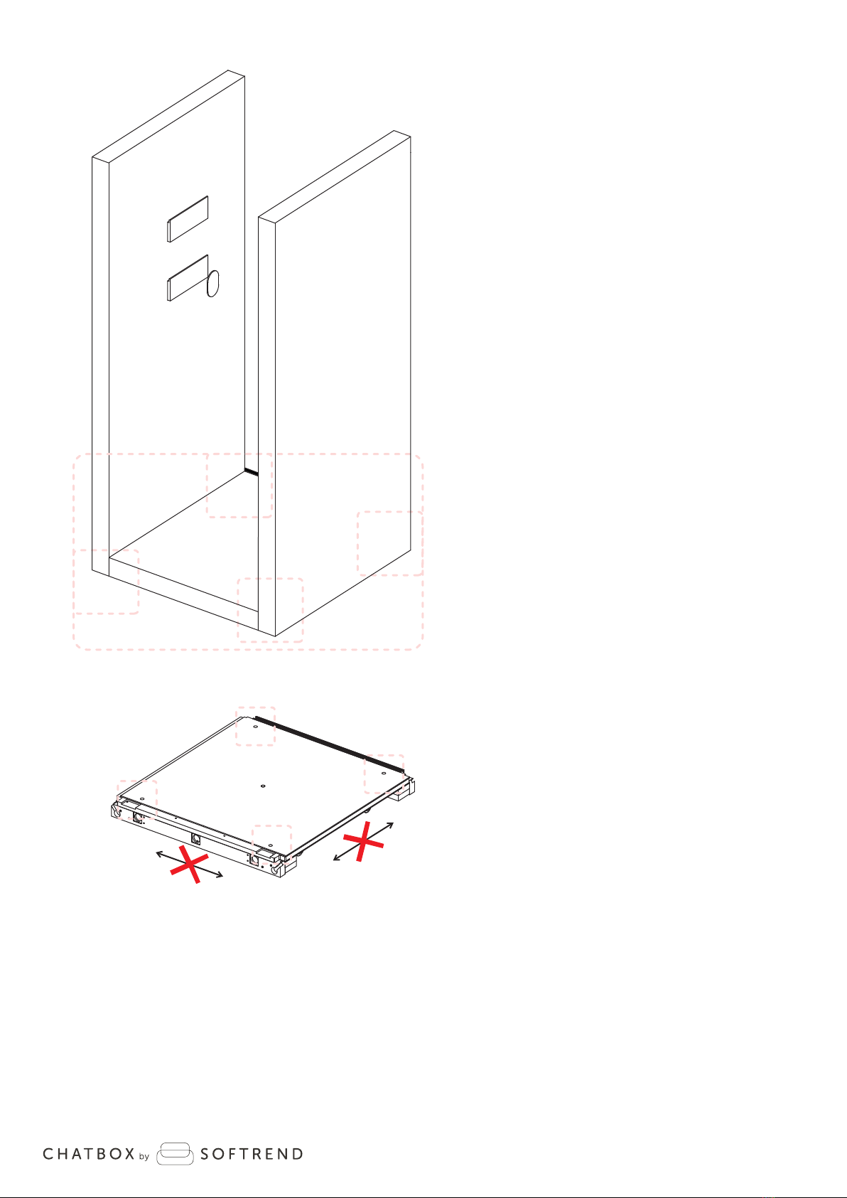
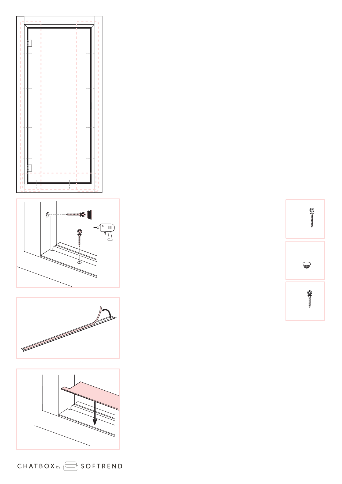
1. Remove carpet plugs on marked posions and use
a long 5mm allen key to adjust 4 levelling glides in the
corners to avoid the floor module from shiing during
assembly.
Note! Glides must be lowered minimally.
85
85
120
120
510
1.
A
85
85
540
120
120
A
A
5mm
2.
A
B
3.
AB
10mm
a
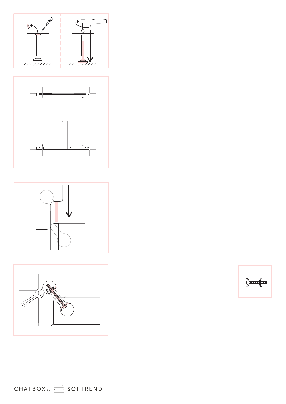
2. Insert the posioning rods aached to side modules
(B and C) into the floor module posioning holes.
3. Secure side modules to the floor
module using part “a” and ghten it
with 10mm wrench.
Note! Make sure there is no gap between
the side and floor module beams.

sorend.ee
E
F
5.
6.
4.
4.
B
D
E
F
5.
4.
4.
C
5
4.
6.
B
D
B5.
F
E
b
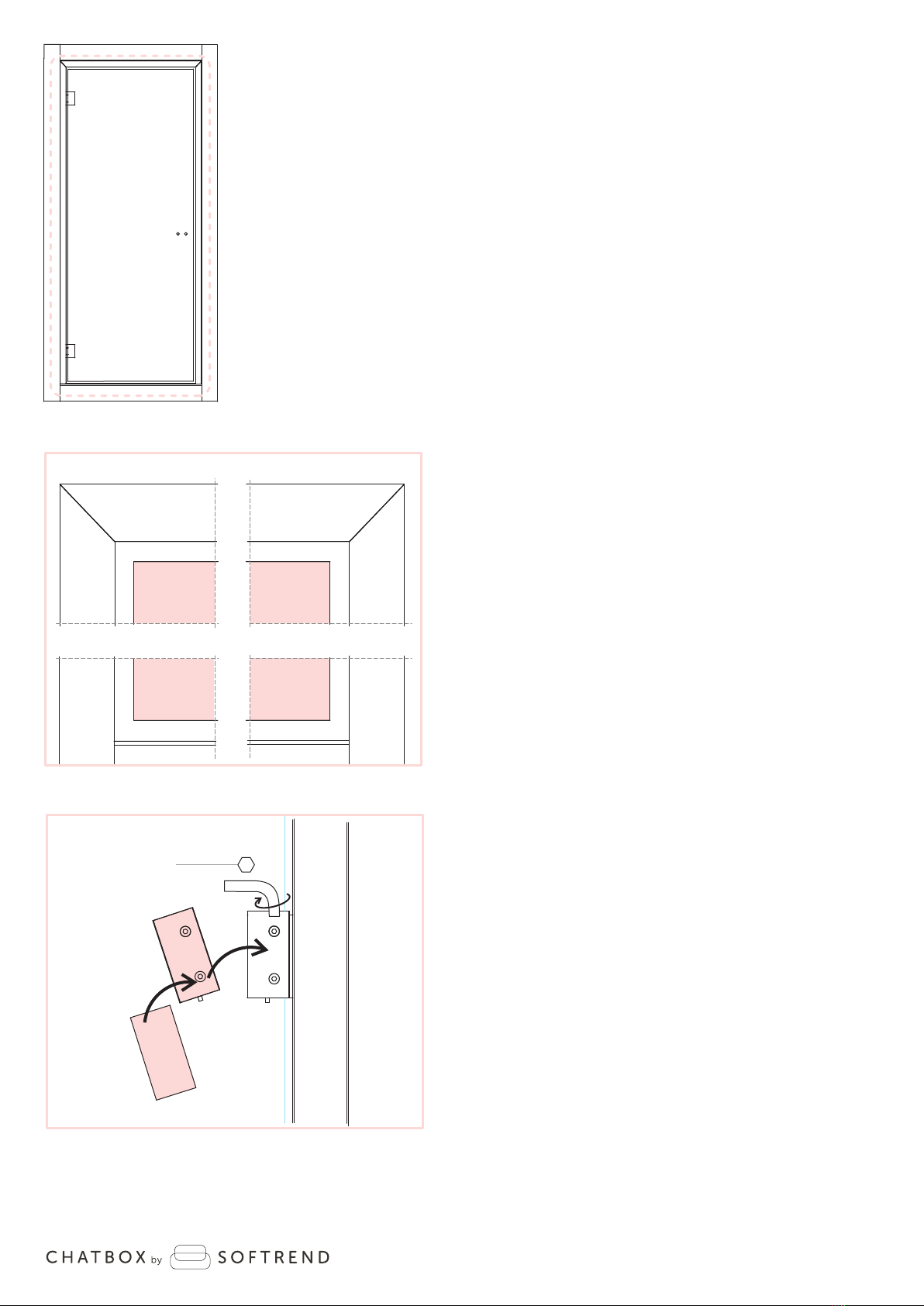
4. Aach assembly support beams (E)
to the side modules.
5. Place safety support beams (F) on top
of the assembly support beams (E).
6. Li ceiling module (D) on top of the side
modules (B and C) and secure the ceiling
module by lowering it between the side modules
unl connectors are even to each other.
T25
x4
5x60mm
b
sorend.ee
6
8.
7.
8.
7.
FF
E
E
LB
B
L
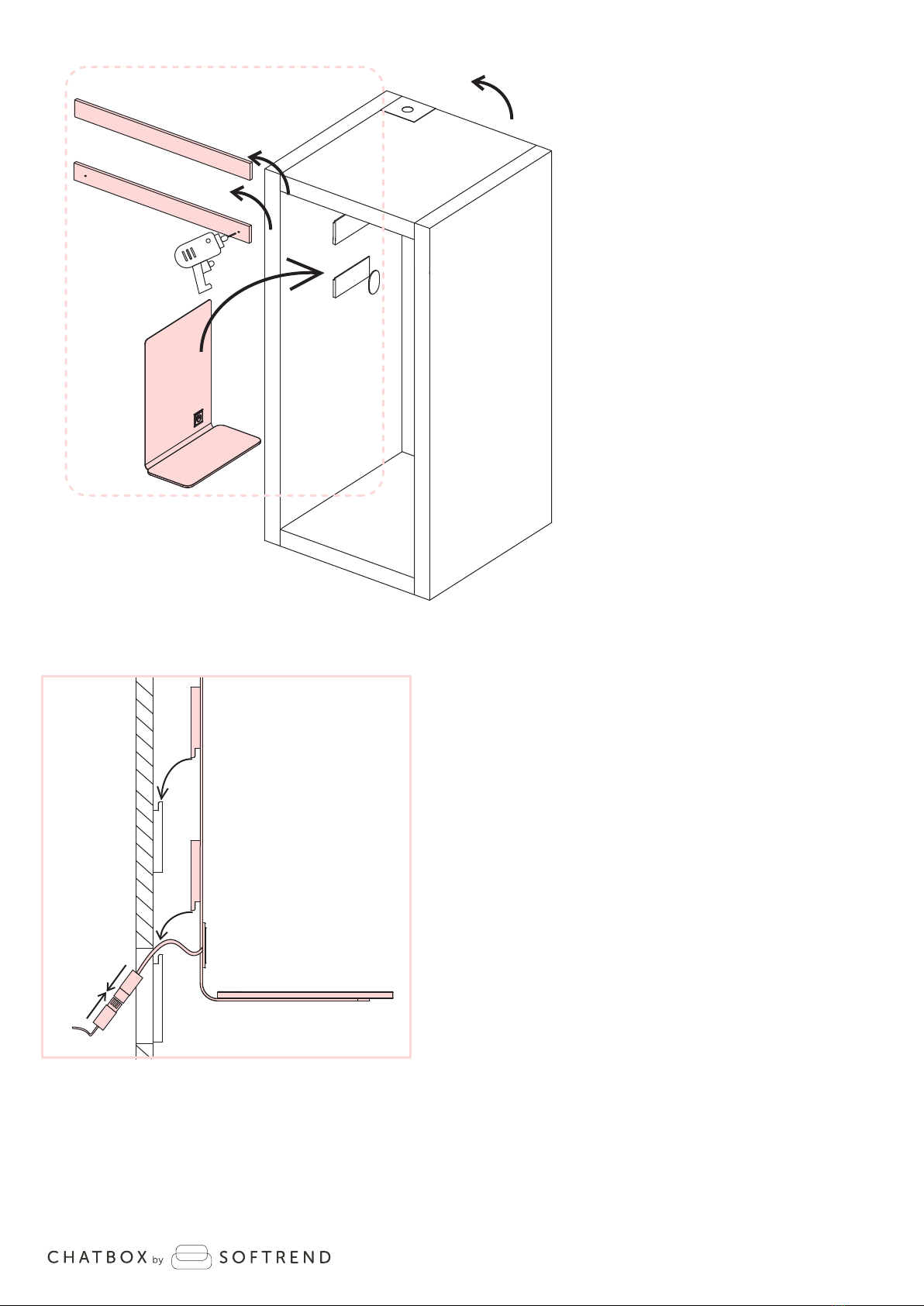
7. Remove support beams (E) and (F) aer
ceiling module is aached.
8. Connect the electrical fings between side module (B)
and table (L), then place table on top of the pre-installed
laths on side module.

sorend.ee
7
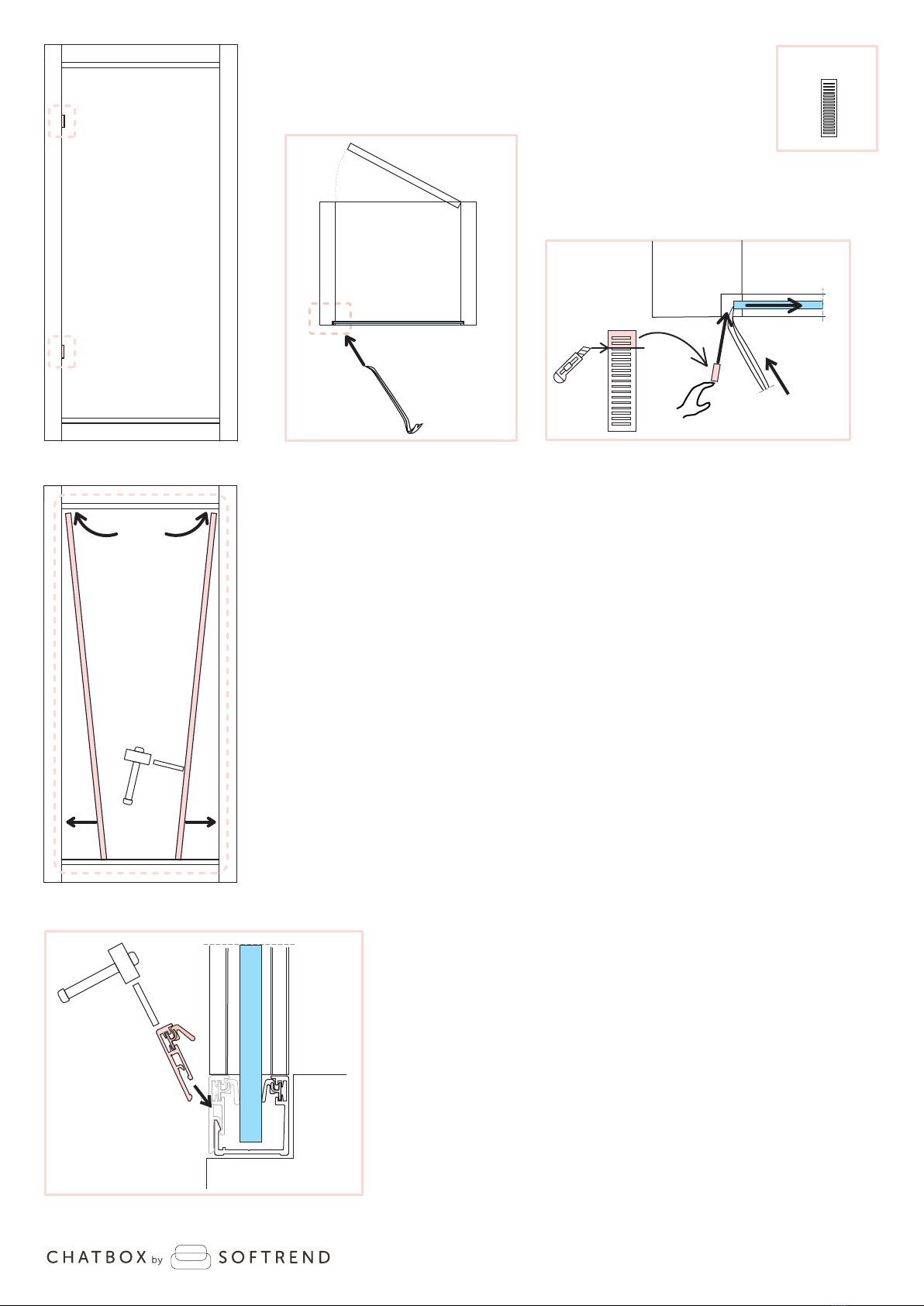
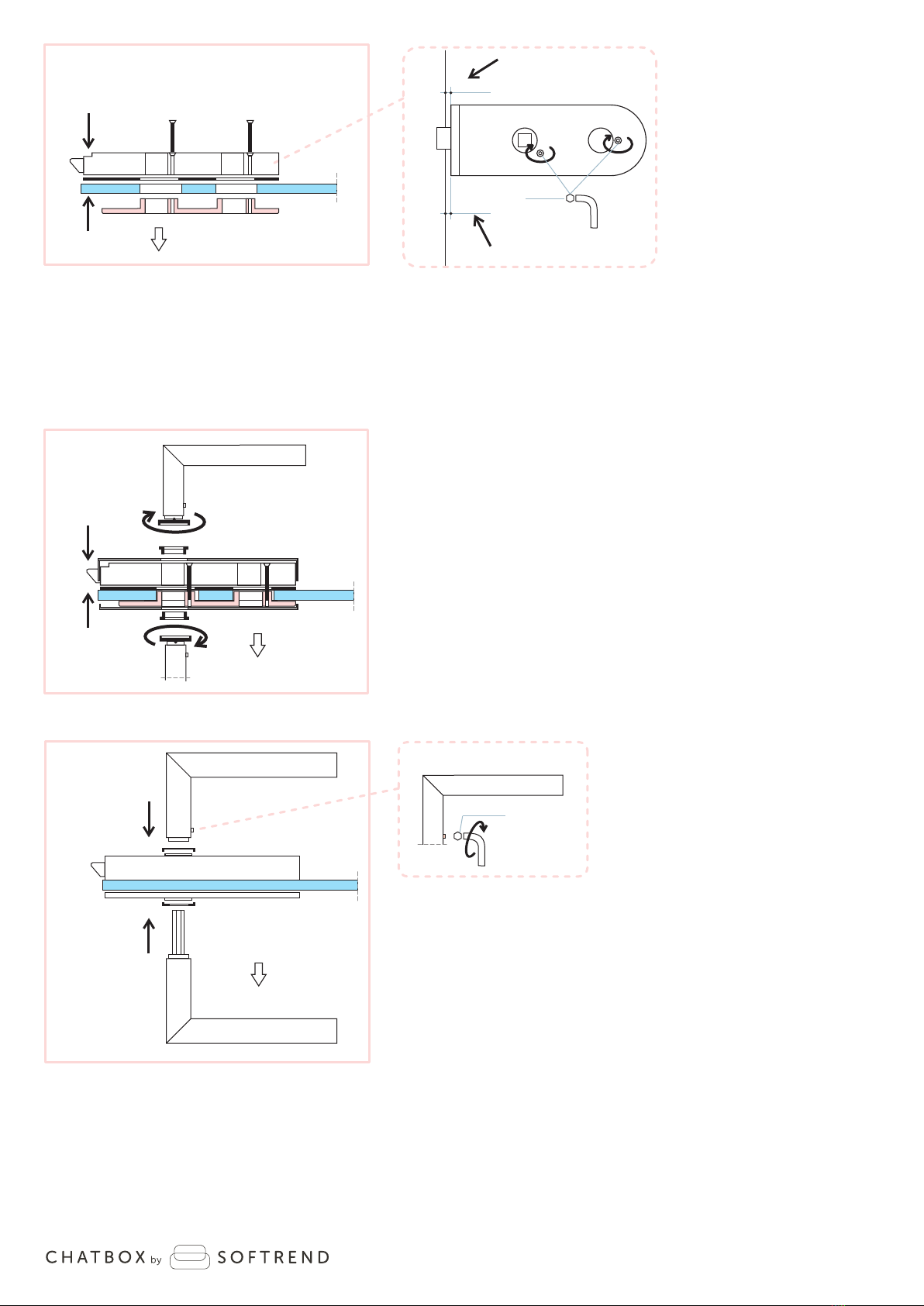
9.1 Click in profile (G2) to the ceiling module using a rubber mallet
and plasc block to secure it.
9. Back-glass panel installaon:
9.2 Place the back-glass panel (G) into the aluminum profiles:
Step 1. Li the glass panel (G) into the top aluminum
profile using sucon cups,
Step 2. Push the boom of the glass panel (G) towards
the front of the cabin,
Step 3. Carefully lower the glass panel (G) unl it
stands on spacers pre-installed into boom
aluminum profile.
1.
2.
D
G
A
3.
9.1
D
A
9.
B
G
C
D
G2
9.2
G2
G2
G1 G1
sorend.ee
9.3
9.3
G2
9.5
A
9.3
B
C
NB!
FRONT
9.4
G2
G2
G1G1
G
x1
e
G
9.3 Secure the back-glass panel by wedging two shims “e” between
the glass panel (G) and the wooden spacer making sure they
are ght.
Carefully shi the glass panel with a plasc crowbar to create
clearance for the shims “e”.
9.4 Click in profile (G1) to the side modules using a rubber mallet
and plasc block to secure it.
9.5 Click in profile (G2) to the floor module using a rubber mallet
and plasc block to secure it.
Note! Shims “e” must be cut into fing size first.
9.3 BACK
C
G
e
Note! Slide the vercal profile (G1) up between the top profile and
side module.
8

sorend.ee
H
10.1
f
f
f
Hff
f
NB!
10.2
9
H
H
H
NB!
10. x1
f
10. Door frame installaon:
10.1 Aach expanding tape “f” to the sides
and top of the door frame (H).
10.2 Posion the door frame (H) in the front
opening and shi it evenly between side
modules.
Note! Expanding tape must be cut in the corners,
not curved around the corners.
Note! Make sure the front face of the door
frame(H) is in line with the front face
of the side modules.
sorend.ee
T15
3,5x35mm
dx4
x8
g
T15
4,5x50mm
cx8
H
A
A
10.3
10.4
10.5
J
HJ
10.6
10
cg
d
cc
cc
cc
cc
d d d d
10.3 Drive in screws (c) to aach the door frame (H)
to the side modules.
Cover the openings with plugs (g).
10.4 Drive in screws (c) to aach the door frame (H)
to the floor module.
10.5 Remove protecon tape from decorave
door threshold (J).
10.6 Aach threshold with glue covered side to door frame.

sorend.ee
11
H
K
11.
11.1
11.2
H
H
3mm
4mm
11.3
H
K
11. Door glass installaon:
11.1 Remove the covering plate from the hinges using a 3mm allen key
to unlock the pin.
11.2 Use 4mm allen key to remove the securing plate from hinges.
11.3 Use sucon cups to li door-glass panel (K)
to the hinges.
Note! Check if the door-glass panel (K) is straight.
If the glass has a curve to it, determine the
inside and outside by using a long straight
level tool.
K
INSIDE
OUTSIDE
NB!
sorend.ee
11.4
K
11.5
11.6
H
4mm
12
K
Max 15Nm
11.4
K
6mm
6mm
6mm
6mm6mm
H
H
H
11.4 Door-glass panel (K) must be equally centered in
relaon to all four sides with approximate 6mm
gap between the glass and door frame.
11.5 Fix the glass by aaching the securing plate back
on the hinges using a 4mm allen key.
11.6 Reaach the covering plate on top of door frame hinges.

sorend.ee
3mm
4mm
13
x1
x1
h
h
h
h
m
m
m
12.
12.1
12.3
12.2
Note! For le handed lock and handle installaon see
manual „Switching the handedness on a lock case“
12. Lock and handle installaon:
12.3 Use 4mm allen key to open the rest of the lock assembly “m”.
12.2 Aach the dedicated tool provided with lock assembly “m” to handle “h”
to remove the lock assembly “m” cover plates.
12.1 Use 3mm allen key to open the preassembled handle set “h”.
sorend.ee
14
4mm
2mm
2mm
m
12.4
INSIDE
K
K
HNB!
NB!
12.4 Place the lock assembly “m” on door-glass and
secure bolts with 4mm allen key.
Note! Make sure part “m” is posioned at a 90-degree angle
in relaon with door-glass edge.
3mm
h
hh
m
m
12.5
12.6
INSIDE
INSIDE
K
K
12.5 Reaach the cover plates on lock assembly “m” using the
dedicated tool with handle “h”.
12.6 Aach handle “h” to lock assembly “m” using 3mm allen key.
Make sure the plasc fasteners are covered with provided
metal covers on both sides.
Note! Handle with the spindle must stay inside the cabin
for safety measures.
In case of emergency you must be able to open the door to exit.

sorend.ee
13.
13.1
13.1
13.1
13.1
13.2
13.2
13.2
13.2
M
M
M N
N
N
P
R
R
P
P
P
15
NB!
1mm1mm
P
N
13. Covering trim installaon:
13.1 Aach engraved covering trim (R) on the front side of ceiling module.
13.2 Aach covering trims (P) on the front/back side of floor module and
back side of ceiling module.
13.3 Aach covering trim (M) on the front/back side of side module and
connect it with pins aached to part (R) and (P).
13.4 Aach covering trim (N) on the front/back side of side module and
connect it with pins aached to part (R) and (M).

sorend.ee
14.
14.
14.
14.
14.
A
A
5mm
min
A
16
A
14. 14. To relocate the cabin, li up previously lowered levelling glides and
move it to desired locaon. Repeat step 1. to secure the cabin again.
Note! Also adjust the middle glide so it supports the middle of the floor.
sorend.ee
Schemac 1.
1
17
D
x1
k
1
B
B
B
A
D
k
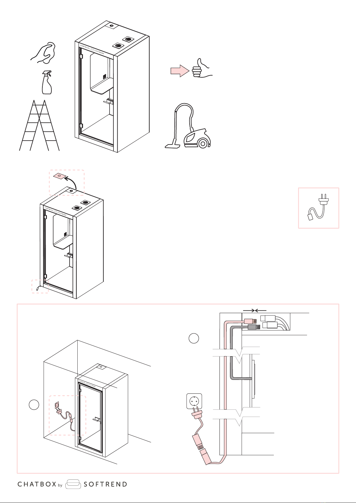
15. 15. Clean all the interior and exterior surfaces.
16. Remove cover plate from the ceiling module
and connue based on one of the following opons:
Opon 1: To connect the cabin to general power supply
with boom connector use Schemac 1.
Opon 2: To connect the cabin to general power supply
with top connector use Schemac 2.
16.

sorend.ee
NB!
2
18
2
B
B
B
A
D
k
17. 17. Make sure LED lights and power socket are funconing properly
and your product is ready for use.
Thank you for choosing Chatbox by Sorend.
Schemac 2.
Popular Office Equipment manuals by other brands

ABSTRACTA
ABSTRACTA Plenty Pod Assembly instructions

Martin Yale
Martin Yale my OFFICE PRODUCTS WC36Cart Assembly instructions

Arcadia
Arcadia 10000 Series installation instructions

Ergotron
Ergotron Neo-Flex WideView WorkSpace Assembly instructions

Unify
Unify OpenScape DECT Phone S5 Base user guide
TTS
TTS Attention Tracker user guide


OLG
OLG COSMIC SYSTEM STRAIGHTLINE installation guide

Nouhaus
Nouhaus Cobra NHG-0005 user manual

OCEE DESIGN
OCEE DESIGN DEN.Booth SASS-0040 B Assembly instructions

Eufficio
Eufficio Innera Classic F installation instructions

Kimball
Kimball National Naviyd Assembly instructions

OfficeSource
OfficeSource PL437T HALF Assembly instructions