OCEE DESIGN DEN.Booth SASS-0040 B User manual
DEN.Booth
2 Person +
1000w & 1200w modules
SASS-0040 B
Assembly Instructions

825d Module = 650w Side Panel
1225d Module = 1050w Side Panel
A x3 1000w Module = 650w Back Panel
1200w Module = 850w Back Panel
2-Way Junction (90°)
Bottom Connector ink
C x2B x2
Z x7
Shell Components (per base 2 person unit)
Bottom Connector ink
Z
1000w Module = 900w Worksurface
1200w Module = 1100w Worksurface
E x1 M6x20 Button Head Bolts arge Worksurface Fixing Bracket Small Worksurface Fixing Bracket
W x12 X x2 Y
Additional Shell Components (per additional unit)
Worksurface Components (Per Worksurface)
x2
3-Way Junction (90°)
D x1
1000w Module = 650w Back Panel
1200w Module = 850w Back Panel
C x1 3-Way Junction (90°)
D x1
825d Module = 650w Side Panel
1225d Module = 1050w Side Panel
A x1 x3
DEN.Booth Assembly Instructions DWG No: SASS-0040
Revision: B (09/12/15)
Drawn by: Jkb
Drawn date: 06/01/15

Tools
4mm Allen Key Cushioned Mallet 13mm Spanner
DEN.Booth Assembly Instructions DWG No: SASS-0040
Revision: B (09/12/15)
Drawn by: Jkb
Drawn date: 06/01/15

$
G0RGXOH Z6LGH3DQHO
G0RGXOH Z6LGH3DQHO
$
G0RGXOH Z6LGH3DQHO
G0RGXOH Z6LGH3DQHO
&
Z0RGXOH Z%DFN3DQHO
Z0RGXOH Z%DFN3DQHO
&
Z0RGXOH Z%DFN3DQHO
Z0RGXOH Z%DFN3DQHO
$
G0RGXOH Z6LGH3DQHO
G0RGXOH Z6LGH3DQHO
'
:D\-XQFWLRQ
%
:D\-XQFWLRQ
%
:D\-XQFWLRQ
=
%RWWRP&RQQHFWRU
/LQN[
;
/DUJH:RUNVXUIDFH
)L[LQJ%UDFNHW
<
6PDOO:RUNVXUIDFH
)L[LQJ%UDFNHW
(
Z'HQ%RRWK Z:RUNVXUIDFH
Z'HQ%RRWK Z:RUNVXUIDFH
;
;
;
<< <
(
Z'HQ%RRWK Z:RUNVXUIDFH
Z'HQ%RRWK Z:RUNVXUIDFH
&
'
&
%
%
$
$
$
(
(
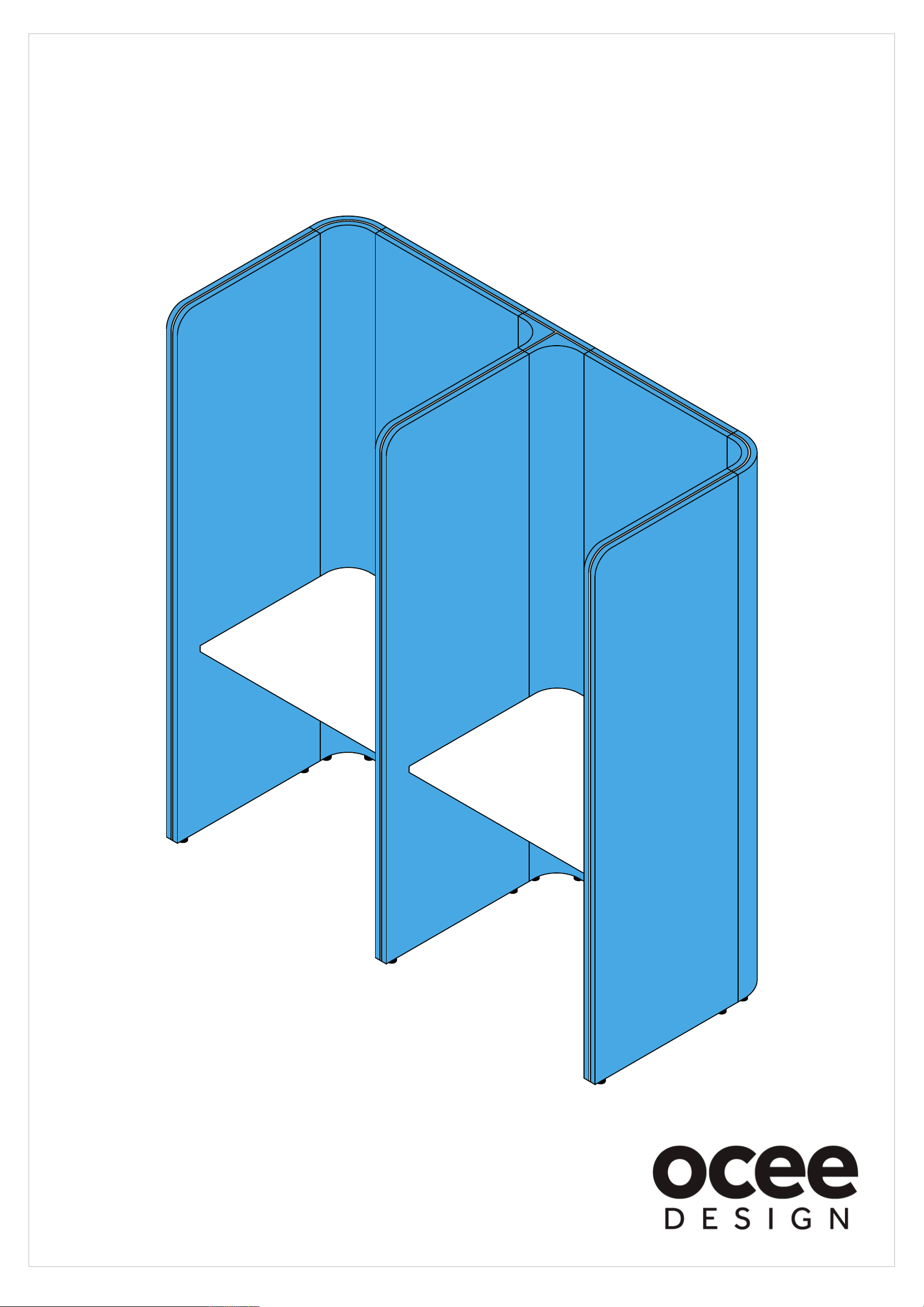
Assembled 2 Person Configuration Illustration (for Reference)
DEN.Booth Assembly Instructions
Before Starting
20mm min
Before assembling make sure that the
levellers on all components are set at a
20mm height minimum.
DWG No: SASS-0040
Revision: B (09/12/15)
Drawn by: Jkb
Drawn date: 06/01/15
A-1
825d Module = 650w Side Panel
1225d Module = 1050w Side Panel
A-4
825d Module = 650w Side Panel
1225d Module = 1050w Side Panel
C-1
1000w Module = 650w Back Panel
1200w Module = 850w Back Panel
C-3
1000w Module = 650w Back Panel
1200w Module = 850w Back Panel
A-2
825d Module = 650w Side Panel
1225d Module = 1050w Side Panel
D-1
3-Way Junction
(90°)
C-2
1000w Module = 650w Back Panel
1200w Module = 850w Back Panel
D-2
3-Way Junction
(90°)
A-3
825d Module = 650w Side Panel
1225d Module = 1050w Side Panel
B-1
2-Way Junction
(90°)
B-2
2-Way Junction
(90°)
Z
Bottom Connector
Link x10
X
Large Worksurface
Fixing Bracket
E-1
1000w Den.Booth = 900w Worksurface
1200w Den.Booth = 1100w Worksurface
X
X
X
Y
YY
E-2
1000w Den.Booth = 900w Worksurface
1200w Den.Booth = 1100w Worksurface
Y
Small Worksurface
Fixing Bracket
YY
X
X
E-3
1000w Den.Booth = 900w Worksurface
1200w Den.Booth = 1100w Worksurface
C-1
D-1
C-3
B-2
B-1
A-2
A-1
E-1
E-2
A-3
E-3
C-2
D-2
A-4
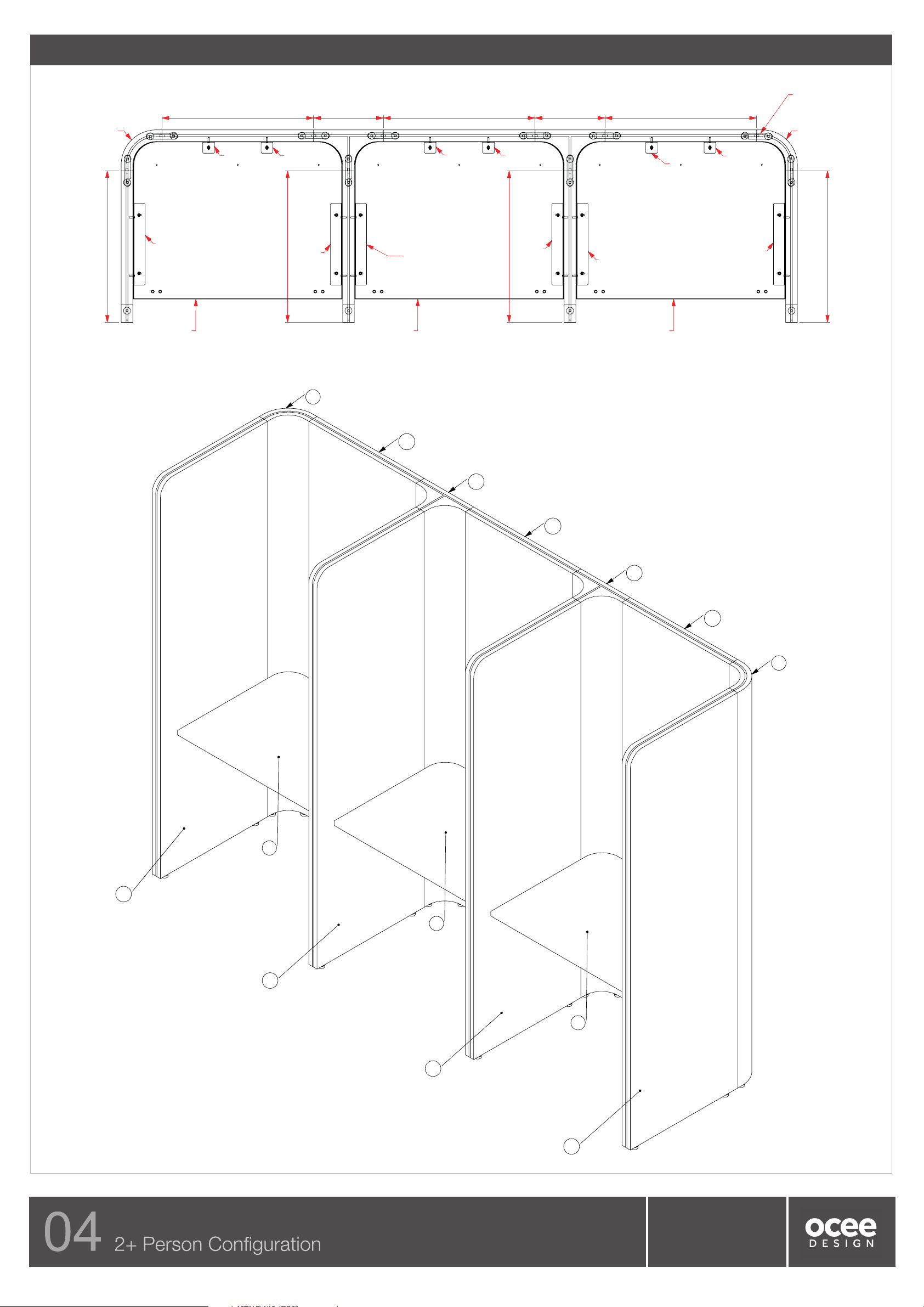
Assembled 3 Person Configuration Illustration (for Reference)
DEN.Booth Assembly Instructions DWG No: SASS-0040
Revision: B (09/12/15)
Drawn by: Jkb
Drawn date: 06/01/15

C-1
1000w Module = 650w Back Panel
1200w Module = 850w Back Panel
C-2
1000w Module = 650w Back Panel
1200w Module = 850w Back Panel
C-3
1000w Module = 650w Back Panel
1200w Module = 850w Back Panel
C-4
1000w Module = 650w Back Panel
1200w Module = 850w Back Panel
D-1
3-Way Junction
(90°)
D-2
3-Way Junction
(90°)
D-3
3-Way Junction
(90°)
A-1
825d Module = 650w Side Panel
1225d Module = 1050w Side Panel
A-5
825d Module = 650w Side Panel
1225d Module = 1050w Side Panel
A-4
825d Module = 650w Side Panel
1225d Module = 1050w Side Panel
A-3
825d Module = 650w Side Panel
1225d Module = 1050w Side Panel
A-2
825d Module = 650w Side Panel
1225d Module = 1050w Side Panel
B-1
2-Way Junction
(90°)
B-2
2-Way Junction
(90°)
Z
Bottom Connector
Link x13
X
Large Worksurface
Fixing Bracket
E-1
1000w Den.Booth = 900w Worksurface
1200w Den.Booth = 1100w Worksurface
X
X
X
YY YY
Y
X
X
E-2
1000w Den.Booth = 900w Worksurface
1200w Den.Booth = 1100w Worksurface
E-4
1000w Den.Booth = 900w Worksurface
1200w Den.Booth = 1100w Worksurface
E-3
1000w Den.Booth = 900w Worksurface
1200w Den.Booth = 1100w Worksurface
XX
Y
Small Worksurface
Fixing Bracket
YY
C-1
D-1
C-4
B-2
B-1
A-2
A-1
E-1
E-3
A-3
E-2
C-2
D-2
C-3
D-3
E-4
A-4
A-5
Assembled 4 Person Configuration Illustration (for Reference)
DEN.Booth Assembly Instructions DWG No: SASS-0040
Revision: B (09/12/15)
Drawn by: Jkb
Drawn date: 06/01/15

1.
Insert the modular screws in the 650w/1050w (module dependent) side panel (A-1)
into the keyholes in the 2-way junction (B-1), making sure that all of the screws have
engaged into the keyholes.
2.
After making sure all of the screws are engaged in the keyholes, tap the top of the
650w/1050w (module dependent) side panel (A-1) with a cushioned mallet to fully engage. Tie
the 650w/1050w (module dependent) side panel (A-1) and the 2-way junction (B-1) together
using a bottom connector link (Z). Insert this over one of the levellers (between the nut and the
bottom of the panel/junction) in the hooked slot and pivot around to insert the other leveller into
the straight slot. Fully tighten both nuts using a 13mm spanner to trap the connector (Z). You
have fully assembled sub-assembly A. Safely secure this assembly until step 7.
3.
Attach the 650w/850w (module dependent) back panel (C-1) to the 3-way junction (D)
as shown above (see step 1 for method).
4.
Tap the top of the 650w/850w (module dependent) back panel (C-1) with a cushioned
mallet to fully engage as shown above.
Tie the 650w/850w (module dependent) back panel (C-1) to the 3-way junction (D)
using a bottom connector link (Z) as shown above (see step 2 for method).
Panel
Connector
M8 nut
eveller
Junction
DEN.Booth Assembly Instructions
Z
Bottom Connector ink
A-1
825d Module = 650w Side Panel
1225d Module = 1050w Side Panel
B-1
2-Way Junction (90°)
Z
Bottom Connector ink
C-1
1000w Module = 650w Back Panel
1200w Module = 850w Back Panel
D
3-Way Junction (90°)
Sub-assembly A
Sub-assembly B
DWG No: SASS-0040
Revision: B (09/12/15)
Drawn by: Jkb
Drawn date: 06/01/15

DEN.Booth Assembly Instructions
5.
Attach the 650w/1050w (module dependent) side panel (A-2) to the 3-way junction
(D) as shown above (see step 1 for method).
6.
Tap the top of the 650w/1050w (module dependent) side panel (A-2) with a
cushioned mallet to fully engage as shown above.
Tie the 650w/1050w (module dependent) side panel (A-2) to the 2-way junction (D)
using a bottom connector link (Z) as shown above (see step 2 for method).
You have now fully assembled sub-assembly B.
7.
Attach the 650w/850w (module dependent) back panel (C-1) of sub-assembly B, to
the 2-way junction (B-1) of sub-assembly A, as shown above (see step 1 for method).
8.
Tap the top of the 650w/850w (module dependent) back panel (C-1) of sub-assembly
B , with a cushioned mallet to fully engage, as shown above.
Tie the 650w/850w (module dependent) back panel (C-1) of sub-assembly B to the
2-way junction (B-1) using a bottom connector link (Z) (see step 2 for method).
If building a 2 person unit continue to step 13.
If building a 3 or more person unit continue to step 9.
Z
Bottom Connector ink
Z
Bottom Connector
ink
A-2
825d Module = 650w Side Panel
1225d Module = 1050w Side Panel
Sub-assembly A
Sub-assembly B
DWG No: SASS-0040
Revision: B (09/12/15)
Drawn by: Jkb
Drawn date: 06/01/15

DEN.Booth Assembly Instructions
12.
Repeat steps 10-11 for every additional sub-assembly made in step 9 then continue
to step 13.
See above for examples of what you should have if you are assembling a 3 person or
4 person configuration.
9.
You have currently built the basis for a 2 person unit. For each additional person on
the unit repeat steps 3 - 6 to build an additional sub-assembly B.
For example:
3 person = build 1 additional sub-assembly.
4 person = build 2 additional sub-assemblies.
etc.
10.
Attach the 650w/850w (module dependent) back panel (C) of the new sub-assembly
B from step 9 to the 3-way junction (D) as shown above (see step 1 for method).
C
1000w Module = 650w Back Panel
1200w Module = 850w Back Panel
11.
Tap the top of the 650w/850w (module dependent) back panel (B) of the new
sub-assembly B from step 9 with a cushioned mallet to fully engage as shown above.
Tie the 650w/850w back panel (B) to the 3-way junction (D) using a bottom
connector link (Z) (see step 2 for method).
Z
Bottom Connector ink
3 Person
4 Person
D
3-Way Junction (90°)
C
1000w Module = 650w Back Panel
1200w Module = 850w Back Panel
D
3-Way
Junction
(90°)
A
825d Module = 650w Side Panel
1225d Module = 1050w Side Panel
Sub-assembly B
Sub-assembly B
Sub-assembly B
DWG No: SASS-0040
Revision: B (09/12/15)
Drawn by: Jkb
Drawn date: 06/01/15

DEN.Booth Assembly Instructions
15.
Attach the 650w/1050w (module dependent) side panel (A-3) to the 2-way junction
(B-2) as shown above (see step 1 for method).
16.
Tap the top of the 650w/1050w (module dependent) side panel (A-3) with a
cushioned mallet to fully engage as shown above.
Tie the 650w/1050w (module dependent) side panel (A-3) to the 2-way junction (B-2)
using a bottom connector link (Z) (see step 2 for method).
You have now fully assembled sub-assembly C.
Z
Bottom Connector
ink
13.
Attach the 650w/850w (module dependent) back panel (C-2) to the 2-way junction
(B-2) (see step 1 for method).
14.
Tap the top of the 650w/850w (module dependent) back panel (C-2) with a cushioned
mallet to fully engage as shown above.
Tie the 650w/850w (module dependent) back panel (C-2) to the 2-way junction (B-2)
using a bottom connector link (Z) (see step 2 for method).
Z
Bottom Connector
ink
Sub-assembly C
A-3
825d Module = 650w Side Panel
1225d Module = 1050w Side Panel
B-2
2-Way Junction (90°)
C-2
1000w Module = 650w Back Panel
1200w Module = 850w Back Panel
DWG No: SASS-0040
Revision: B (09/12/15)
Drawn by: Jkb
Drawn date: 06/01/15
Other OCEE DESIGN Office Equipment manuals

OCEE DESIGN
OCEE DESIGN DEN.Cube User manual

OCEE DESIGN
OCEE DESIGN DEN SASS-0081 User manual

OCEE DESIGN
OCEE DESIGN SASS-0100 User manual

OCEE DESIGN
OCEE DESIGN Den Seat SASS-0079 A User manual

OCEE DESIGN
OCEE DESIGN SASS-0096 User manual

OCEE DESIGN
OCEE DESIGN SASS-0102 User manual

OCEE DESIGN
OCEE DESIGN DEN.Panel Triple SASS-0068 A User manual

OCEE DESIGN
OCEE DESIGN DEN.Curve User manual

OCEE DESIGN
OCEE DESIGN DEN 675d Module User manual

OCEE DESIGN
OCEE DESIGN DEN SASS-0082 User manual


