Sol-Expert DoubleLight User manual
SOL-EXPERT
group
group
10+
Return the device to a
certified provider at the
end of its useful life!
You will also need:
Soldering iron, solder, tweezers,
pen, hot glue gun, side cutters
We recommend:
Assembly and soldering should be supervised
by an experienced person!
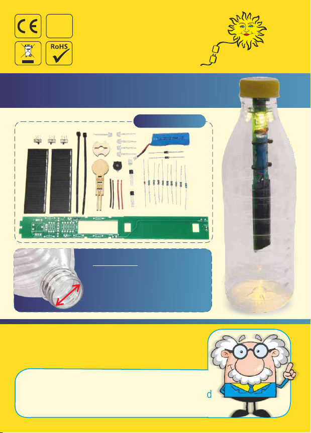
PET Bottle Solar Lamp
Soldering and DIY kit - pimp your PET bottle!
Important:
When buying the PET
bottle, ensure the neck is
at least 28 mm wide!
Contents: Item No. 79334

! SAFETY NOTES !
Read the full instructions before use and keep in a safe location
for future reference. They contain important information.
We assume no liability for personal injury or property damage
due to improper handling or failure to observe the safety notes!
This will void the warranty/guarantee.
This kit is only intended to be battery powered.
Never connect the kit to the 230 V mains!
If the rechargeable battery is defective, always replace with a
new equivalent rechargeable battery (LiFePO 400mAh).
In schools, training facilities, DIY rooms and workshops, using
soldering irons and accessories must be supervised by a trained,
responsible person.
Absolute danger to life!
The soldering iron, the solder and the soldered parts become
very hot. Be very careful!
Never allow children to use a soldering iron or soldering
accessories unsupervised! They are not toys. Using a soldering
iron must be diligently supervised by an adult experienced in
soldering.
We recommend using a soldering iron holder to set the soldering
iron down safely during use.
SOLDERING TIP: A round or matte solder point is a poor solder
point and must be touched up. If necessary, extend the soldering
time or the soldering temperature and use new solder for
electronic work.
Always use a soldering mat when soldering! It prevents parts
and the PCB from slipping.

General: Please return electronic parts to certified disposal
companies after use. These will ensure the parts are disposed of in
compliance with the law. This is good for the environment and your
part in actively protecting the environment. Battery ordinance:
You have purchased a battery-powered product from us. The
rechargeable battery has a limited life and must therefore be
replaced at some point. Used batteries do not belong in household
rubbish. Consumers are required by law to return batteries to a
suitable collection point. Used batteries contain valuable raw
materials which can be recycled. You can also return
your used rechargeable battery to us:
SOL-EXPERT group, Mehlisstrasse 19, 88225 Baindt,
Germany. You can purchase new rechargeable batteries
for this product directly from us.
It can further result in hazards such as short-circuit, electric
shock, fire, etc.
Do not modify any part of the product! Any other use not specified
in the instructions is prohibited and will damage the product.
The power source and the tools and soldering equipment
required for assembly are not included.
Save the company address - Not suitable for
children under 3 years! - Contains small parts!
The soldering kit is not a toy and is suitable for
soldering novices.
The safety notes and instructions for use of the power source
used must be observed.
PLEASE NOTE!
ENVIRONMENTAL NOTES
You can optionally switch off 2 of the LEDs so the lamp stays on
longer in winter or in continued poor weather. Using the detailed
instructions, the various parts such as resistors, LEDs,
switches, etc. are soldered to the PCB step by step. Once the
PCB is fully assembled and installed in a PET bottle, you will
have a cool, fully functional solar lamp.
With this cool soldering kit you can turn a standard PET bottle
(min. neck width 28 mm) into a great solar lamp. The solar cell
charges the rechargeable battery in this kit during the day. When
it starts to get dark, the lamp automatically switches on and stays
on all night - depending on the battery level. It uses a total of 4
white and one rainbow (multicolour) LEDs.
How the solar-powered PET bottle lamp works
This solar bottle lamp is one small step in this
The oceans are full of them and the piles of rubbish keep
growing. Not recycling PET bottles is a big problem for the
environment and for humans and animals too. It's time to break
new, innovative ground.
PET bottles:
creative part in protecting the environment!
direction. Reusing one of the many PET bottles
to build this solar lamp is your active and
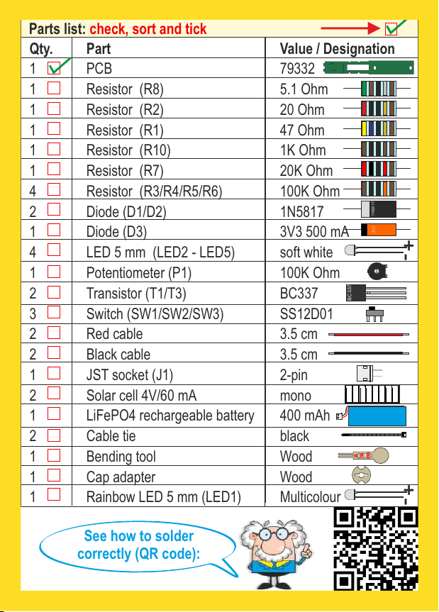
See how to solder
correctly (QR code):
Qty. Part
Value / Designation
1 PCB
79332
1 Resistor (R8)
5.1 Ohm
1 Resistor (R2)
20 Ohm
1 Resistor (R1)
47 Ohm
1 Resistor (R10)
1K Ohm
1 Resistor (R7)
20K Ohm
4 Resistor (R3/R4/R5/R6) 100K Ohm
2 Diode (D1/D2)
1N5817
1 Diode (D3)
3V3 500 mA
4 LED 5 mm (LED2 - LED5) soft white
1 Potentiometer (P1)
100K Ohm
2 Transistor (T1/T3)
BC337
3 Switch (SW1/SW2/SW3)
SS12D01
2 Red cable
3.5 cm
2 Black cable
3.5 cm
1 JST socket (J1)
2-pin
2 Solar cell 4V/60 mA
mono
1 LiFePO4 rechargeable battery
400 mAh
2 Cable tie
black
1 Bending tool
Wood
1 Cap adapter
Wood
1 Rainbow LED 5 mm (LED1)
Multicolour
Parts list: check, sort and tick
1N5817
3V3
++ --
BC337
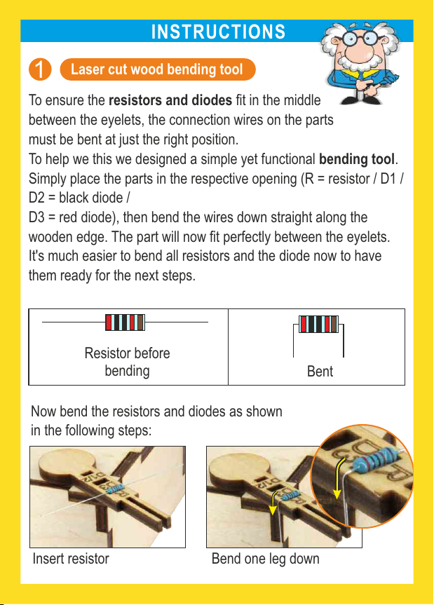
INSTRUCTIONS
Laser cut wood bending tool
To ensure the resistors and diodes fit in the middle
between the eyelets, the connection wires on the parts
must be bent at just the right position.
D3 = red diode), then bend the wires down straight along the
wooden edge. The part will now fit perfectly between the eyelets.
It's much easier to bend all resistors and the diode now to have
them ready for the next steps.
To help we this we designed a simple yet functional bending tool.
Simply place the parts in the respective opening (R = resistor / D1 /
D2 = black diode /
1
Bent
Resistor before
bending
Now bend the resistors and diodes as shown
in the following steps:
Insert resistor Bend one leg down
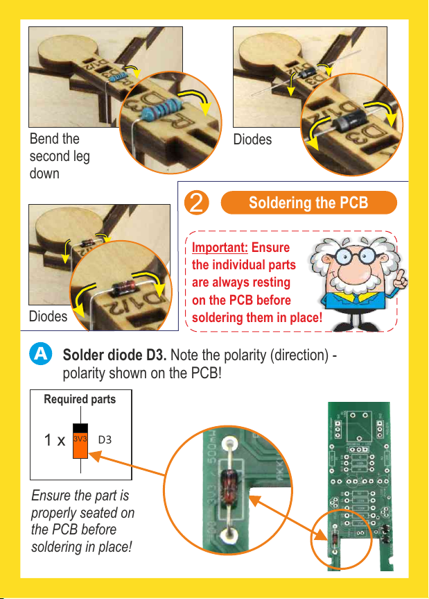
Bend the
second leg
down
Diodes
Diodes
Important: Ensure
the individual parts
are always resting
on the PCB before
soldering them in place!
ASolder diode D3. Note the polarity (direction) -
polarity shown on the PCB!
Required parts
1 x 3V3 D3
Soldering the PCB
2
Ensure the part is
properly seated on
the PCB before
soldering in place!
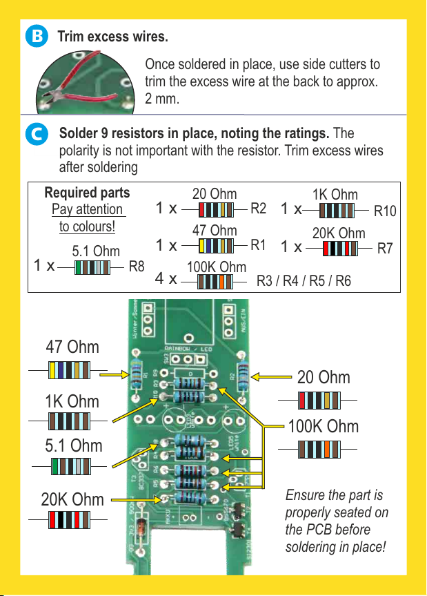
Trim excess wires.
B
Once soldered in place, use side cutters to
trim the excess wire at the back to approx.
2 mm.
5.1 Ohm
20 Ohm
47 Ohm
1K Ohm
20K Ohm
100K Ohm
1 x
1 x
1 x
1 x
1 x
4 x
Required parts
Pay attention
to colours!
R8
R2
R1
R10
R3 / R4 / R5 / R6
R7
Ensure the part is
properly seated on
the PCB before
soldering in place!
5.1 Ohm
20K Ohm
1K Ohm
47 Ohm
20 Ohm
100K Ohm
CSolder 9 resistors in place, noting the ratings. The
polarity is not important with the resistor. Trim excess wires
after soldering

DSolder diode D1 and D2. Note the polarity (direction),
polarity shown on the PCB!
Required parts
2 x D1/D2
1N5817
Ensure the
part is
properly
seated on the
PCB before
soldering in
place!
E
IMPORTANT!
this location
on the left, in
Notch (cut-out)
Required parts
1 x J1
Solder socket J1 for the battery. Note the polarity! The
socket has a notch. It must be facing to the left as shown
in image "B". Otherwie the socket will extend beyond
the PCB.
Ensure the
part is properly
seated on the
PCB before
soldering in
place!
Bild B

Du kannst die Füßchen vom
Prozessor behutsam etwas
nach innen biegen. Dann gleitet
das IC besser in die Löcher!
TIPP:
F
Ensure the part is
properly seated on
the PCB before
soldering in place!
Required parts
1 x
3 x
P1
SW1/SW2/SW3
GSolder transistors T1 & T3. Note the polarity (1)! Bend the
middle leg of the transistor slightly back (2). Solder in place
and trim excess legs.
flat side
rounded side
Transistor
top view
1Transistor side view
bend
middle
leg to
the back
2
2 x BC337
Required parts
T1 / T3
Solder potentimeter P1 and switches SW1/SW2/SW3.
Trim excess legs.
The polarity is not important.
flat side
rounded
side
Flat side
Flat side
Rounded
side
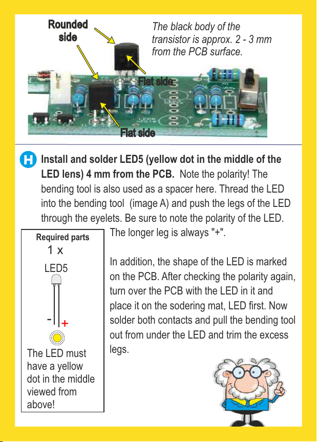
Gerundete
Seite The black body of the
transistor is approx. 2 - 3 mm
from the PCB surface.
Install and solder LED5 (yellow dot in the middle of the
LED lens) 4 mm from the PCB. Note the polarity! The
bending tool is also used as a spacer here. Thread the LED
into the bending tool (image A) and push the legs of the LED
through the eyelets. Be sure to note the polarity of the LED.
The longer leg is always "+".
In addition, the shape of the LED is marked
on the PCB. After checking the polarity again,
turn over the PCB with the LED in it and
place it on the sodering mat, LED first. Now
solder both contacts and pull the bending tool
out from under the LED and trim the excess
legs.
H
Required parts
1 x
-
+
LED5
The LED must
have a yellow
dot in the middle
viewed from
above!
BILD??
Flat side
Flat side
Rounded
side

3
Image A
1
Insert short "-"
leg here
Insert long "+"
leg here
2
4
Result

Install and solder LED2 (yellow dot in the middle of the
LED lens) to the of the PCB 4 mm from the PCB.back
Same as step H.
I
1 x
-
+
LED2
Insert short
leg "-" here
Insert long
leg "+" here
You must turn the PCB to install LED 2.
1
!
Result
2 3
Required parts
LED must have
a yellow dot in
the middle
viewed from above!
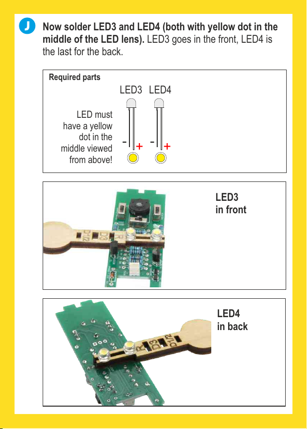
J
-- ++
LED4
LED3
Now solder LED3 and LED4 (both with yellow dot in the
middle of the LED lens). LED3 goes in the front, LED4 is
the last for the back.
LED3
in front
LED4
in back
Required parts
LED must
have a yellow
dot in the
middle viewed
from above!

KNow solder LED1 (rainbow) to the PCB. Use the spacer
again. LED1 is fitted from the front. Note the correct polarity.
Long leg "+", short leg "-". This LED does not have a yellow
dot in the middle. After soldering, bend LED1 downward.
Required
parts
1 x
-
+
LED1
LTin cables: The four cables, red and black, are only tinned
on The cable one side. The other side stays untinned.
jacket is already scored, Simply pull the jacket off at both
ends. To tin, heat the wires with the soldering iron and add
soldering tin until all wires are covered with solder.
tinned untinned
Required parts
2 x
2 x

M
First presolder the (i.e. apply contacts for the solar cell
some solder to both solder contacts), then solder the two
tinned cable ends to the contacts. Attention: red cable to
" " and black cable to "-", the loose cable ends pointing +
toward the middle of the solar cell.
Solder the cables to the solar cells.
Required parts
2 x 2 x
NInsert the cables for one solar cell through the top cut-out
(yellow marking) and place the solar cell on the back of
the PCB.
Turn over the PCB with solar cell. Now insert the black cable
through the eyelet "Solar1-" and solder from the other side
of the PCB.
1
2
2 x
Änderungen und Irrtümer vorbehalten - März 2019 / Christian Repky ©
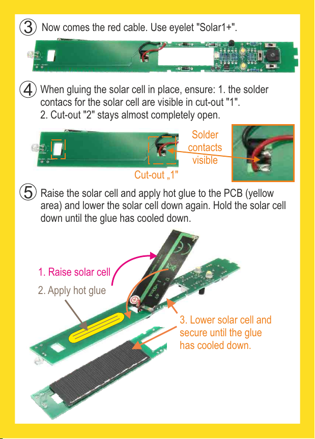
Now comes the red cable. Use eyelet "Solar1+".
When gluing the solar cell in place, ensure: 1. the solder
contacs for the solar cell are visible in cut-out "1".
2. Cut-out "2" stays almost completely open.
Raise the solar cell and apply hot glue to the PCB (yellow
area) and lower the solar cell down again. Hold the solar cell
down until the glue has cooled down.
Klappe die Solarzelle hoch und bringe
Heißkleber auf die Platine auf (gelbe
Fläche) und klappe dann die Solarzelle
wieder runter. Halte die Solarzelle
gedrückt, bis der Kleber ausgekühlt ist.
Cut-out „1"
Solder
contacts
visible
3
4
5
6
1. Raise solar cell
2. Apply hot glue
3. Lower solar cell and
secure until the glue
has cooled down.
Cut-out "2"

Insert the cables of the remaining solar cell through the
bottom cut-out (yellow marking). Solder the red cable to
eyelet Solar2+, the black cable to Solar2-.
again be inside the cut-out.
Raise the solar cell, apply hot glue to the PCB (yellow area)
and lower the solar cell. Hold the solar cell down until the glue
has cooled down.The solder points for the solar cell must
Result
6
7
Apply hot glue
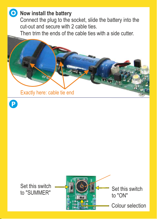
O
P
Then trim the ends of the cable ties with a side cutter.
Now install the battery
Connect the plug to the socket, slide the battery into the
cut-out and secure with 2 cable ties.
Exactly here: cable tie end
Set this switch
to "ON"
Colour selection
Set this switch
to "SUMMER"
Set the
potentiometer
to approx.
"5 o'clock"
TEST RUN:
You have now soldered everything that was necessary and
are now ready for the first test run. Set the SW2 switch to
"ON" and the SW1 switch to "SUMMER" and turn the
potentiometer to approx. "5 o'clock". Then you only need to
make sure the solar cell is not receiving any daylight. After
all, the solar cell also serves as a photoelectric switch.
Meaning the lamp only comes on when it's dark.
Cover the solar cell or go into a dark room to test the lamp.
Use the SW3 switch to change between
white and multi-colour LED.
1
2
3
4
5
6
7
8
9
10
11 12

Now glue the PCB into the bottle
3
A
A
Important note: Glue must not run onto this red area.
If it does, you will need to carefully pick out the glue or the
bottle will not close.
Use the hot glue gun to add two little glue dots.
B
Then push the cover adapter into the glue dots (preferably
with tweezers). Centre the cap adapter on the cap.
C
You can now carefully fill the empty space around the cap
adapter (pink area) with hot glue. Except the " " in Red zone
image "A". Also keep glue away from the orange area.
D
"Red zone": no glue allowed!
BC D
If it doesn't come on, check the solder points
and verify all parts are soldered the correct way
around. (see Troubleshooting p. 24)
Lamp comes on? EXCELLENT JOB
TEST
AB C D
This manual suits for next models
1
Table of contents
Other Sol-Expert Lantern manuals


Popular Lantern manuals by other brands


olympia electronics
olympia electronics SLIM LIGHT Series manual

eaglelighting
eaglelighting EL-HYP-124 installation guide

Home Decorators Collection
Home Decorators Collection HB7064-306 Use and care guide

Acuity Controls
Acuity Controls nLIGHT Programming instructions

Performance In Lighting
Performance In Lighting CRICKET+ 10 installation instructions

olympia electronics
olympia electronics POWER LIGHT Series quick start guide