Sol-Expert VARIOSAND User manual
SOL-EXPERT
group
group
SOL-EXPERT
group
group
10+10+
Keep the address of the company.
Not suitable for children under 3
years! - Contains small parts!
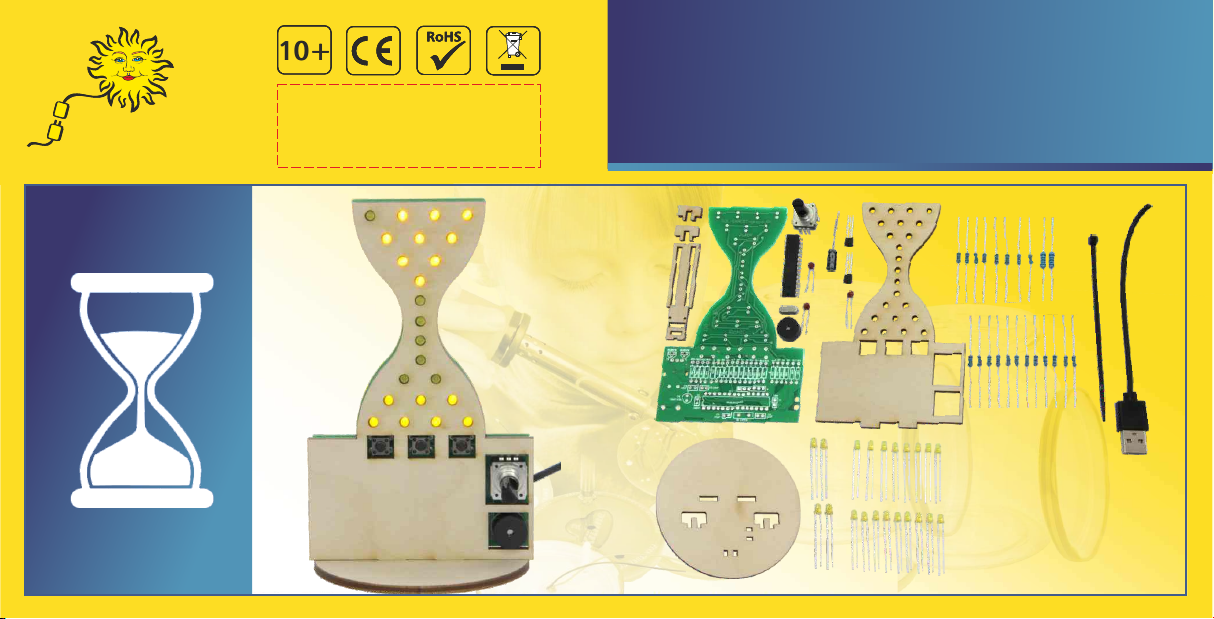
VARIOSAND - The extraordinary
hourglass soldering kit
MADE IN EUROPE
Item No.: 76700
1 minute
to 109
minutes
Can be set from:
Generally: Please return electronic parts to certified disposal companies after use. These will ensure the parts are disposed of in
compliance with the law. This is good for the environment and your part in actively protecting it.
ENVIRONMENTAL NOTES:
This kit is only intended to be USB powered.
Never connect the kit to 230 V mains voltage! This poses an absolute danger to life!
Keep these instructions for future reference! They contain important information.
Always use a soldering mat when soldering! It prevents parts and the PCB from slipping.
The soldering iron, the solder and the soldered parts become very hot. Be very careful!
We recommend using a soldering iron holder to set the soldering iron down safely during use.
SAFETY NOTES:
For children and youngsters we recommend:
Assembly and soldering should be supervised by an adult with soldering skills!
!
Important notes!
!

What is special about this hourglass is that a different time ("amount of sand" between 1 - 109 minutes) can be selected on each
occasion. For instance, you can set VARIOSAND to 5 minutes for a soft-boiled egg or 10 minutes for a hard-boiled egg. When the time
has expired, the "sand" has visually trickled down from the top to the bottom, the beeper sounds to tell you the egg is ready!
The VARIOSAND circuit board kit is ideally suited for newcomers to soldering, all budding electronics engineers, hobby technicians and
anyone who enjoys working with a soldering iron or soldering station. More than 60 parts are soldered on the "VARIOSAND" board,
including an already programmed microprocessor. Once everything has been completely assembled, you'll have a wonderful
programmable hourglass.
This intelligent hourglass is powered by a power bank or directly from a USB port, such as a mobile phone charger. This eliminates the
need for a costly extra battery. This is good for the environment and helps to make you more of a climate activist.
With VARIOSAND you can also store 3 separate times that you can then simply retrieve at the touch of a button. It might look something
like this: On button "1" you store 15 minutes for the "crispy pizza" and on button "2" 4 minutes for "perfect tea-brewing time". Of course,
you can decide for yourself which times you want to save. By the way, you can paint, varnish or decorate the wooden front or customise
it as you wish. Let your imagination take over and turn VARIOSAND into a real eye-catcher.
The VARIOSAND soldering kit - the extraordinary hourglass

Parts list Check the parts:
You will also need:
Soldering iron, solder, side cutters, tweezers, powerbank (USB),
possibly PCB assistant (an extra hand)
VARIOSAND - The extraordinary hourglass
1 Capacitor (C6) 10 uF/10V
2 Transistor (T1+T2) BC557B
3 Push buttons (SW2-SW4) 3301
2 Capacitor (C4+C5) 10 nF/10V
1 Processor (IC1) ATMEGA328
2 Capacitor (C2+C3) 22 pF/10V
1 Capacitor (C1) 100 nF/10V
1 Quartz (Q1) 16MHz
12 Resistor (R5-R16) 330 ohms
2 Resistor (R2+R4) 1.5K ohms
4 Resistor (R19-R22) 10K ohms
23 3 mm LED (LED1-22) yellow
2 Resistor (R1+R3) 4.7K ohms
2 Resistor (R17+R18) 180 ohms
1 PCB 76700
Qty. Part Value / Designation
103
104
22
BC557B
10 uF
1 Piezo (J5) 12M
1 Encoder (SW1) Encoder
1 USB connecting cable 40 cm
1 Set of wooden parts 4 parts
1 Bending aid for resistors
1 Cable tie
1 Wood glue
ASSEMBLY INSTRUCTIONS
Set out your tools and switch on your soldering iron.
When using an adjustable soldering station/iron, we recommend a
soldering temperature of about 320 - 340 degrees and a soldering tip
about 2-3 mm wide.
Everything OK? Let's get started!
Set out and sort all parts. This will make it easier for you to later identify
the individual parts you will need during the steps.
And it doesn't hurt to tidy up your work space so you can quickly find
all parts.
Preparation
orange
orange
black
black
brown
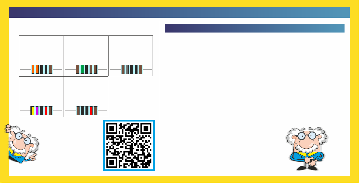
330 ohms
black
black
brown
grey
brown
180 ohms
black
yellow
violet
rot
brown
4.7K ohms
black
brown
black
red
brown
10K ohms
green
black
brown
brown
brown
1.5K ohms
Tips from a pro
on how to solder
properly (QR):
Resistor colour code:
)
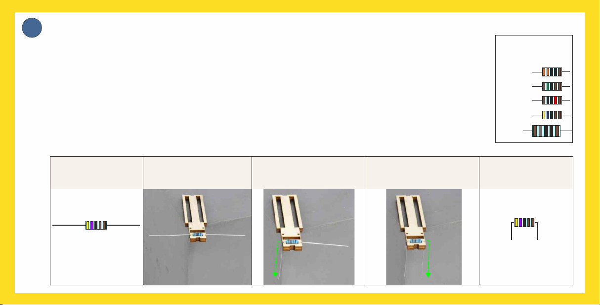
3
APrepare resistors with the bending tool.
The connecting wires of the two somewhat larger resistors (180 Ohms) can be bent down directly on their
bodies. Then they will fit perfectly between the soldering points.
In order for the small resistors R1-R16 and R19-R22 to fit properly between the soldering points, the
conntecting wires must be bent exactly in the correct location. To make this easier, we have designed a
simple yet functional bending tool. Simply place the resistors in the notch and bend the leads down straight
along the wooden edge downwards into the notch.
The part will now fit perfectly between the soldering points.
Insert resistor: Bend one leg down: Bend the other leg down:
12 x
2 x
4 x
2 x
2 x
Resistors
to bend:
And this is how it is done:
Resistor before: Bent to completion:
ü

Shorten any protruding wires.
Now the first resistors are soldered
onto the PCB
After soldering, cut off the protruding
wires on the back, shorten to approx.
2 mm with the side cutter.
Place the PCB in front of you so that you can
read the resistor values printed in white. Then
place the 4 resistors individually one after the
other on the board and solder them.
Make sure that each component is as flat as
possible on the board before soldering!
(see drawing below)
You will now need these parts:
4 x
4 x
Trim here to 2 mm length:
Part wire Soldering
point
Part
PCB
3
B
10K ohms
10K ohms
R19-R22
R19-R22
3
C
1 x PCB
PCB
So that the component does not fall out
again and lies flat on the circuit board, you
can you can bend the wires outwards slightly. Then solder and shorten wires
to 2 mm (see point C)
Insert part
Solder component flat on the PCB
Bend wires
outwards
here

Now solder the remaining resistors one by one.
DYou will now need these parts:
1.5K ohms
4.7K ohms
330 ohms
180 ohms
2 x
2 x 2 x
12 x
R2+R4
R1+R3
R5 - R16
R17+R18
1.5K ohms 330 ohms 180 ohms
4.7K ohms 4.7K ohms
And again trim the protruding wires.
After soldering, cut off the protruding
wires on the back, shorten to approx.
2 mm with the side cutter.
Trim here to 2 mm length:
Part wire Soldering
point
Part
PCB

ENow solder on the two capacitors and
afterwards the quartz...
You will now need
the following parts:
2 x
1 x
C2+C3
Q1
22
22 22
22 pF/10V
16 MHz
... and then trim the protruding wires.
After soldering, cut off the protruding
wires on the back, shorten to approx.
2 mm with the side cutter.
Trim here to 2 mm length:
Part wire Soldering
point
Part
PCB

TIPP 1- 3 F
You will now
need the
following part:
If no leg is visible in a soldering point, pull the IC out again, bend the leg carefully and plug the processor back in. Check again
and then solder.
To make it easier for the processor to slide between the soldering points, you can bend all the legs inwards a little. (Image 1)
When plugging in the processor, you must pay attention to its alignment. The processor has a notch (rounding), which must be
oriented to the left when you insert it. In the magnified image below you can see the notch very well. (Image 2)
Now we come to the heart of the circuit: the processor!
When you have plugged in the IC, turn the board over and check whether all 28 legs are visible in the soldering points (image 3).
1 x
IC1 You can move the legs of the
processor inwards. Then the
IC slides better into the
soldering points!
Notch
(rounding)
at this point
1
2
3
Image 1 Image 2 VERY VERY IMPORTANT! Image 3
Are all 28 feet visible?
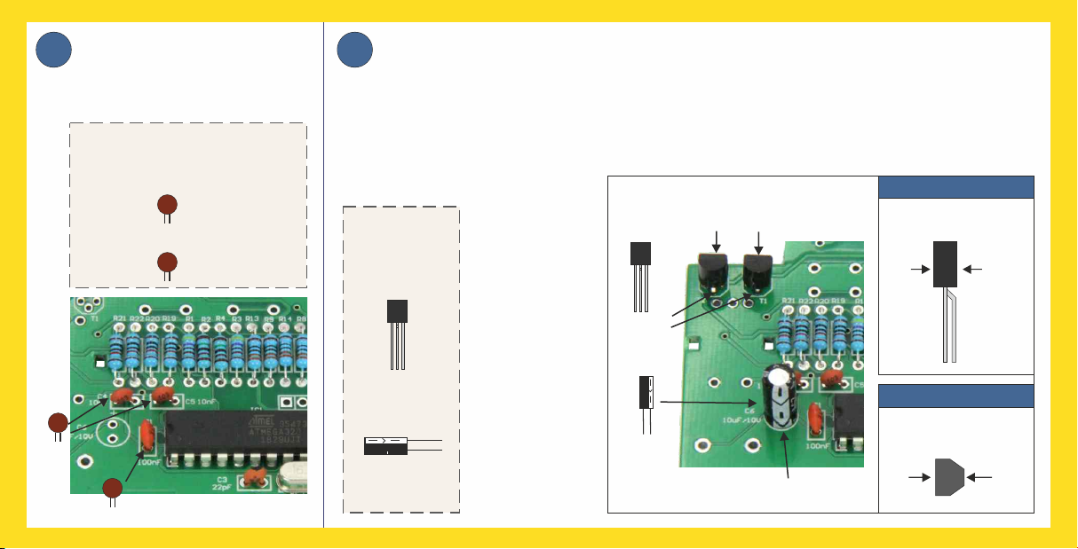
Solder the capacitors C4 +
C5 and then C1, trim solder
wire to 2 mm.
G
You will now need the
following parts:
2 x
1 x
C4+C5
C1
103
103
104
10 nF/10V
100 nF/10V
HSolder on the transistors and capacitor. Bend the middle leg of the transistors slightly
backwards (image 1), pay attention to the alignment (image 2) and solder the transistors.
Pay attention to the polarity of capacitor C6, which is now soldered on. I.e. the leg marked
"-" (minus) must be pushed into the correct soldering point. Then solder the capacitor in
place and trim the soldering wires to 2 mm.
2 x
1 x
T1+T2
10 uF/10V
BC557B
BC557B
Transistor view
from above
fflat side
fflat side
rounded
side
rounded
side
Transistor
side view
bend middle
leg
backwards
The legs of the
transistors are
very close
together.
Therefore please
solder
particularly
carefully so that
you do not
create a short
circuit between
the legs.
Attention:
You will now
need the
following parts:
10 nF/10V
T1+T2
C6
BC557B
BC557B
Flat side
transistor
10 uF
+-
"-" MINUS is here
10 uF
104
100 nF/10V
Image 1
Image 2
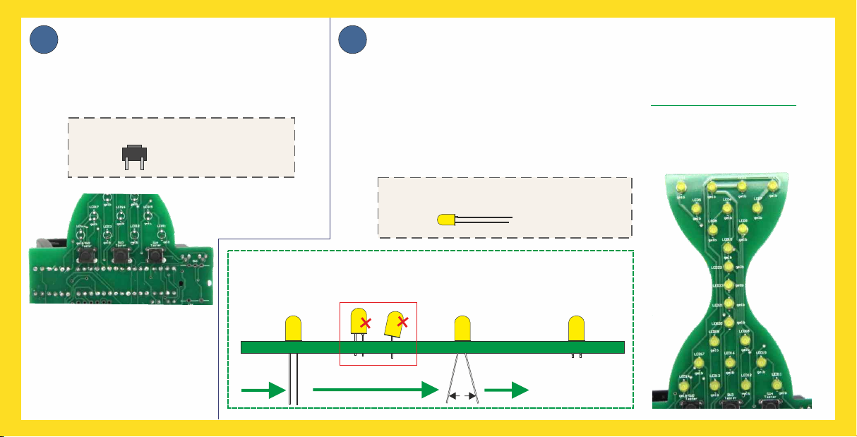
I
The buttons are soldered onto the on
the back. Therefore, turn the PCB over
and only then solder on the buttons.
Solder on the buttons. JNow come the LEDs.
Solder on one LED after the other. It is essential that you observe the polarity
of the LED. The longer leg is always PLUS "+" and has to be in the soldering
point marked with "+". Also make sure that each (see LED lies flat on the PCB
drawing below). This is very important to ensure that the wooden front can be
fitted accurately later. It makes sense to solder the LEDs 1 / 4 / 14 / 11 first.
Do not forget to trim the wires.
You will now need the following parts:
You will now need the following parts:
3 x SW2-SW4
23 x LED1-23
ü
Solder the LEDs flat on the PCB:
Solder and
trim wires
Insert the LED
lying flat
Bend wires
bend outwards
-
+
TIP:
As the soldering legs of the
buttons are thicker, you can
increase the soldering
temperature to 400°.
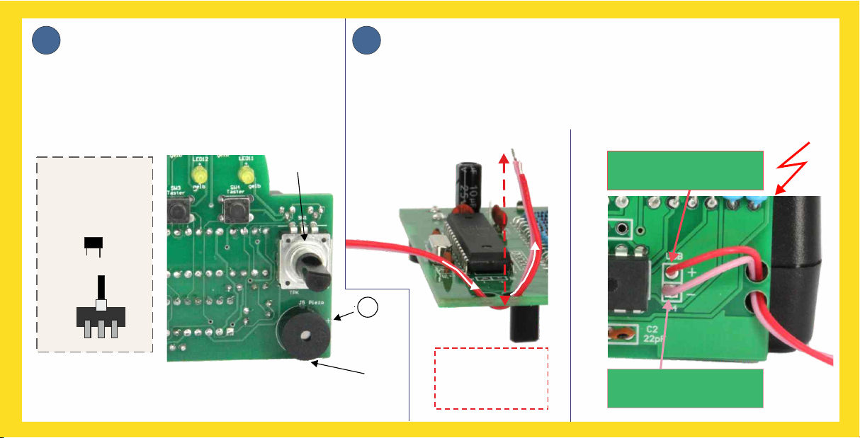
KPIEZO and encoder.
Ensure that the polarity of the piezo is correct.
You will find a "+" symbol on both the circuit
board and the piezo. After soldering, remove
the sticker from the piezo. Then solder on the
encoder and trim the protruding legs.
L
1.5 cm through the two holes. To solder, push the strand of each cable through
soldering point and solder from the other side. The red cable to "+" and the
pink or white cable to "-".
First thread both individual cables (red and pink/white) together approx.
Solder the USB connection cable.
Red or
Red wire "-“
You will now
need the
following parts:
1 x
1 x SW1
SW1
J1
J1
+
It is essential to observe
the wire colour:
white wire „+"
approx. 1.5 cm
(red arrow)
Cable length:
TiP: When soldering these parts, you can increase
the temperature of the soldering iron slightly, to about 400°.
Red wire "-“
Red or
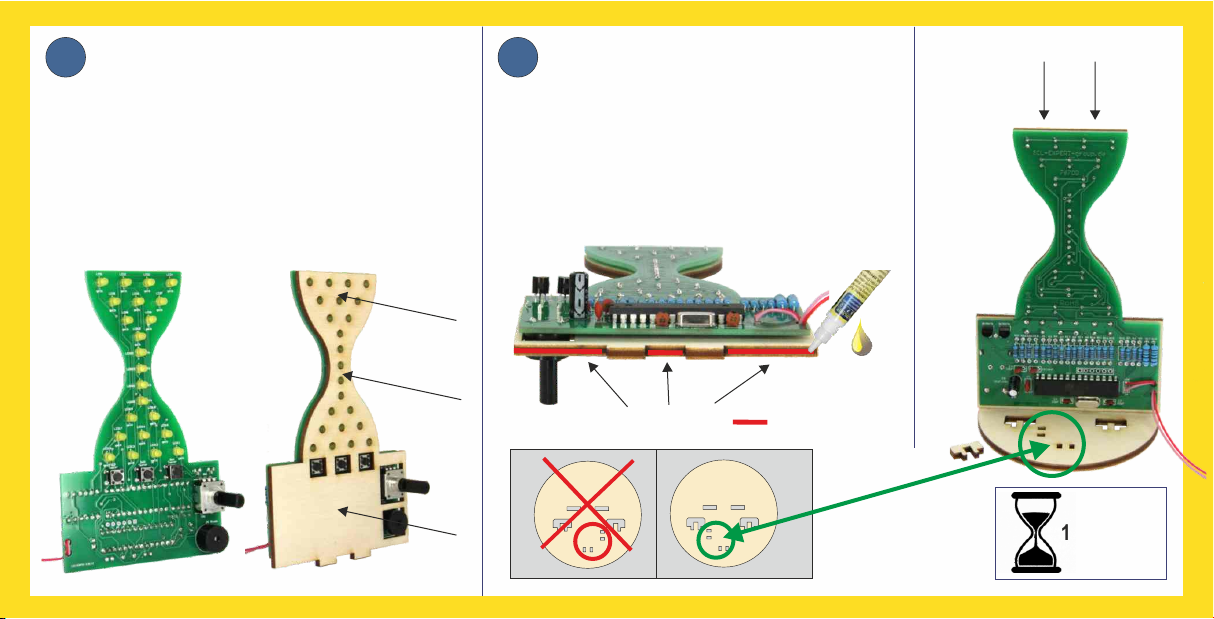
M N
Then push the front cover over the LEDs.
Align the LEDs if necessary!
Before attaching the wooden front, double-
check that all the protruding wires have been
shortened to 2 mm.
Mount the front cover.
Apply a little wood glue to the areas
marked in red and then then press the
hourglass onto the the base plate.
Then wait approx. 10 minutes until the
glue has glue has dried.
Glue the hourglass to the base plate.
Gluing surface:
10 minutes
Pay attention to the
alignment of the
base plate!
ü
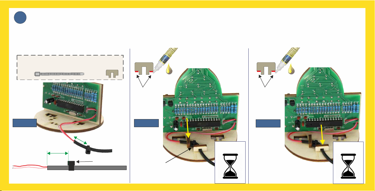
OFasten the cable tie tightly around the cable with approx. distance to the cable casing (see image 1). Trim the protruding 1.5 cm
piece of the cable tie with the side cutters. Then apply wood glue to the first cable fixings (image 2), slide it over the cable and
press it into the base. Allow to dry for 5 minutes and then glue in the second fixation (image 3). Now let the glue allow to dry for
approx. 10 minutes.
Mount the cable strain relief.
Apply
glue here
You will now need the following parts:
Apply
glue here
1 x 2 x
Cable tie
5 minutes
10 minutes
Cable tie between
the wooden fixings
1,5 cm Cable ties
USB connecting cable
Image 1 Image 2 Image 3
PQNow connect the USB cable of the VARIOSAND hourglass to a USB port (e.g. power bank or mobile
phone power supply). Now all the LEDs should trickle down from the top like the sand in a real
hourglass. If this does not happen, the following list may help you to check possible causes:
VISUAL INSPECTION:
Now we can move
on with Q:
Not working,
nothing happens!
Individual LEDs
do not light up
No time change
when turning the
rotary wheel
There is no signal
after the time has
expired
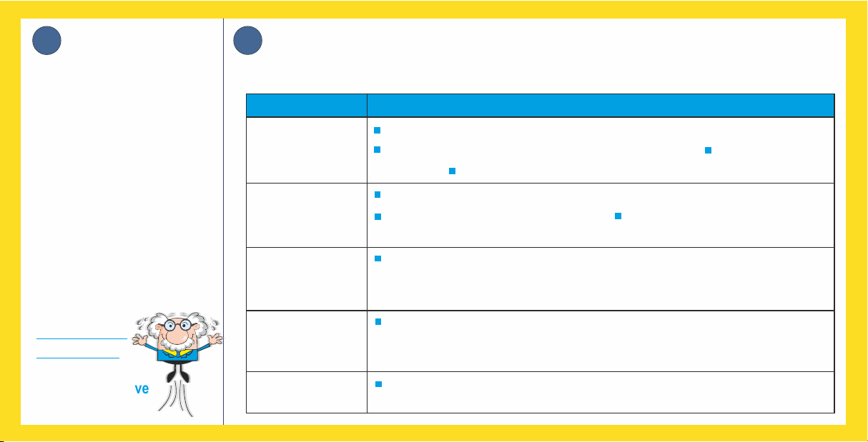
Malfunction: Troubleshooting:
USB cable correctly soldered with the correct polarity? Powerbank fully
charged? Check transistors for short circuit
Check all solder joints on the processor for short circuits
Re-solder the solder joints of the malfunctioning LED with some solder.
Check the solder joints of the resistors Is the LED soldered the right way
around? Is the "-" on the negative? If necessary, desolder and turn 180 degrees.
Check and re-solder all solder joints on the encoder
Check the piezo (buzzer) for polarity and re-solder the soldered joints.
Preset time cannot
be programmed
Check and re-solder the solder joints of all the buttons.
WELL DONE!!
Just sit back and relax and let
your mind wander a little.
When you are fully chilled out,
take another look at the the
assembly instructions from the
beginning and check whether
you have done everything as
described in the instructions.
Pay particular attention that no
short circuits have occurred
and that the values of the
resistors, etc.
are correct.
Everything OK?
When you connect the hourglass to a USB port (power bank or mobile phone charging adapter), the programme starts and the "sand" starts
trickling from top to bottom. After that, the middle LED starts to light up permanently, telling us it is ready for use.
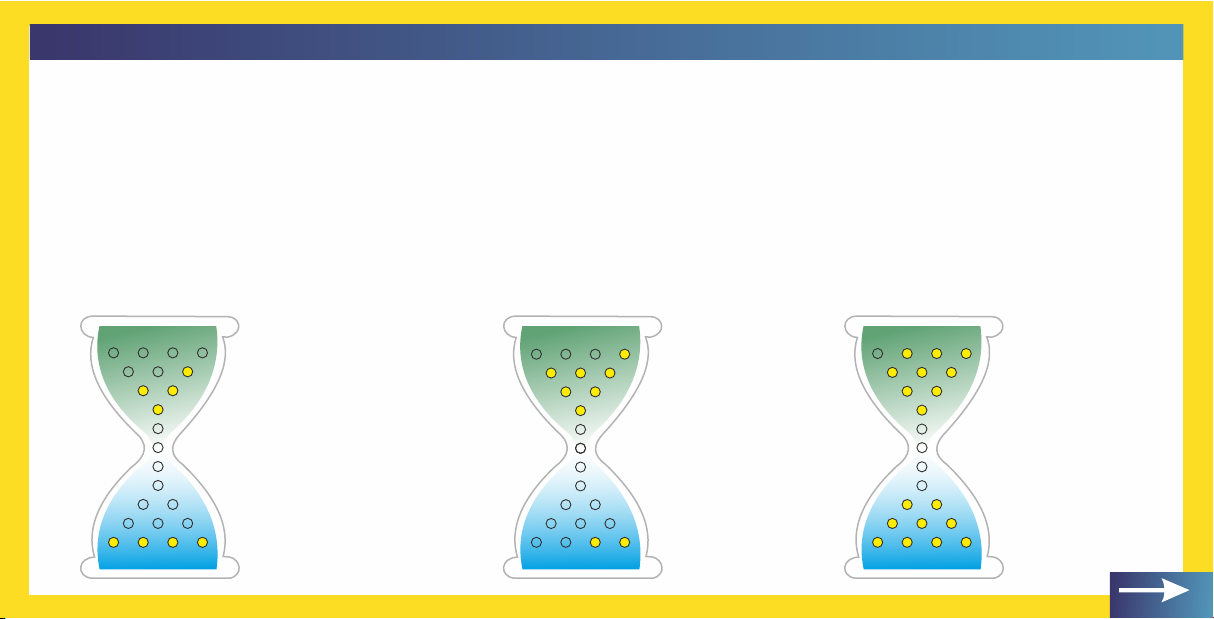
Manual time setting
In the lower section of VARIOSAND , each illuminated LED stands for 1 minute and in (highlighted in blue in the example below)
the upper section , each illuminated LED stands for 10 minutes. Both numbers together (highlighted in green in the example below)
indicate the total time set. In the following, you will see 3 examples that illustrate how you can read the time:
If the button on the rotary encoder is now held down for approx. 2 seconds, the middle LED starts to flash briefly. Then the lower right LED
lights up. If the rotary encoder is now turned clockwise, more and more LEDs will be switched on.
Instruction manual
= 40 minutes
= 4 minutes
40 mins + 4 mins = 44 minutes
The total time is calculated by by
adding the two sections, i.e.:
= 70 minutes = 90 minutes
= 2 minutes = 9 minutes
The total time is:
72 mins
The total time is:
99 mins.
Beispiele:

Instruction manual
If you turn the rotary encoder anti-clockwise, e.g. to correct the time, the LEDs are individually switched off again. Once you have set the
desired time, you confirm this by briefly pressing the head of the rotary encoder.
All the upper LEDs now start to light up and, depending on the time set, the "sand" will gradually start to trickle down from the top to the
bottom. When all the "sand" has reached the lower area and the time has expired, the buzzer sounds. You can switch it off by pressing any
button or switch.
VARIOSAND can store a total of three freely selectable times, which can then be retrieved simply by pressing a button.
The memory buttons
And this is how it works:
Programme the desired time:
Use the rotary encoder to set the desired time and then press one of the three buttons under
which you want to save the time. The LEDs start flashing briefly and the desired time is stored
under the pressed button. The flashing LEDs go out and the middle LED lights up: the desired
time has been permanently stored. If you want to change the stored time, repeat the
procedure. The new programmed time overwrites the previous one.
And this is how
you can programme
the desired time
)

Instruction manual
Stopping the timer before ist up
And when the eggs are boiled, the pizza is ready, the smell of cake is wafting through your home and you no longer need VARIOSAND,
unplug it and keep it safe and dry for the next time.
Retrieve desired time
The set time is accessed by pressing the corresponding button. The programme starts automatically.
Briefly pressing the rotary encoder button interrupts the programme sequence and VARIOSAND automatically returns to the
switch-on state.
www.sol-expert-group.de
SOL-EXPERT group, C.Repky
Mehlisstrasse 19 - D-88255 Baindt
Tel.: +49 (0)7502 - 94115-0 - Fax: +49 (0)7502 - 94115-99
Errors and changes reserved
©
July 2021 / Christian Repky
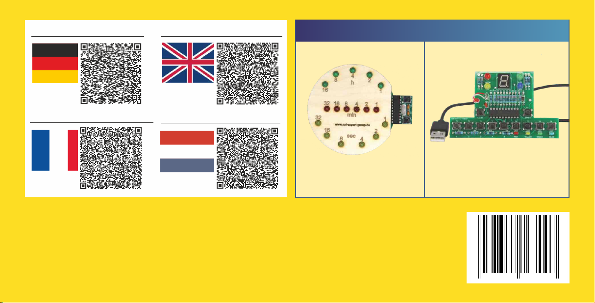
Click here for the instructions:
Hier geht es zur Anleitung:
Cliquez ici pour les instructions:
Klik hier voor de instructies:
4 0 3 7 3 7 3 7 6 7 0 0 7
Shows the time digitally!
Item no.: 76334
Keep your brain fit!
Item no.: 79300
Other great SOL-EXPERT group soldering kits:
Binary Clock soldering kit TrainYourBrain soldering kit
This manual suits for next models
1
Table of contents
Other Sol-Expert Lantern manuals


Popular Lantern manuals by other brands


olympia electronics
olympia electronics SLIM LIGHT Series manual

eaglelighting
eaglelighting EL-HYP-124 installation guide

Home Decorators Collection
Home Decorators Collection HB7064-306 Use and care guide

Acuity Controls
Acuity Controls nLIGHT Programming instructions

Performance In Lighting
Performance In Lighting CRICKET+ 10 installation instructions

olympia electronics
olympia electronics POWER LIGHT Series quick start guide