Sola AURA-3215 How to use

WWW.SOLAGRUPO.COM
AURA-3215
Pressurized hopper
MAINTENANCE AND DOSAGE
STARTING
MANUAL

2
SOLÀ seed drills, planters and fertilizer spreaders are manufactured in a highly specialized environment
and our factory has a vast network of satised customers.
SOLÀ machines use highly advanced technology and are guaranteed to work without malfunctions in a
large variety of conditions. The SOLÀ machines are provided with easy-to-use and ecient devices and
perform excellently with only minimum operator maintenance.
This manual will help you use your SOLÀ product with the maximum eciency.
Certied quality system
1st Edition – February 2017
Ref.: CN -811105/GB
Created by: M.A. SOLÀ
It is forbidden to copy any part of this manual.
Specications are subject to change or modication without notice.
The pictures included do not necessary show the standard version.

3
SUBJECT INDEX
1- INTRODUCTION................................................................................................................................................................................. 5
2- SAFETYINSTRUCTIONS..................................................................................................................................................................... 6
2.1 SAFETY SYMBOLS..........................................................................................................................................................................................................6
2.2 GENERAL SAFETY DISPOSITIONS..............................................................................................................................................................................6
2.3 USE DEPENDING ON DESIGN......................................................................................................................................................................................7
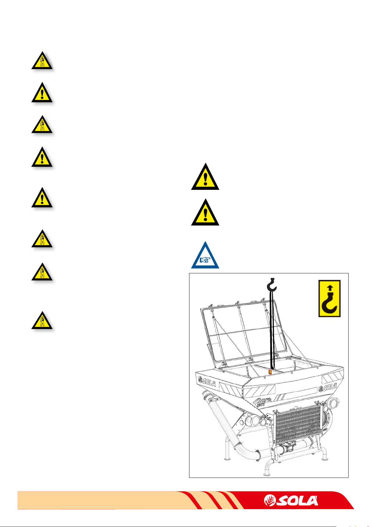
2.4 LOADING AND UNLOADING INSTRUCTIONS ..........................................................................................................................................................7
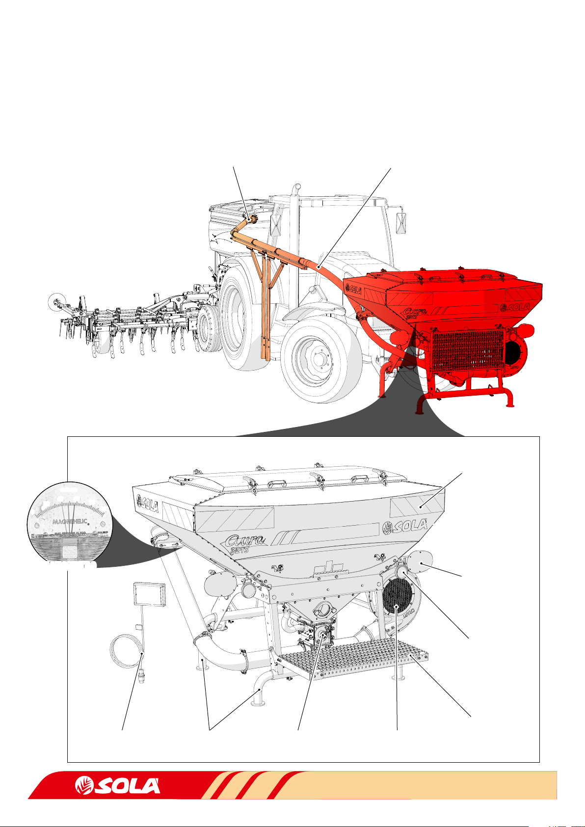
3. GENERALDESCRIPTION .................................................................................................................................................................... 8
3.1 GENERAL OVERVIEW ....................................................................................................................................................................................................8
3.2 TECHNICAL FEATURES .................................................................................................................................................................................................9
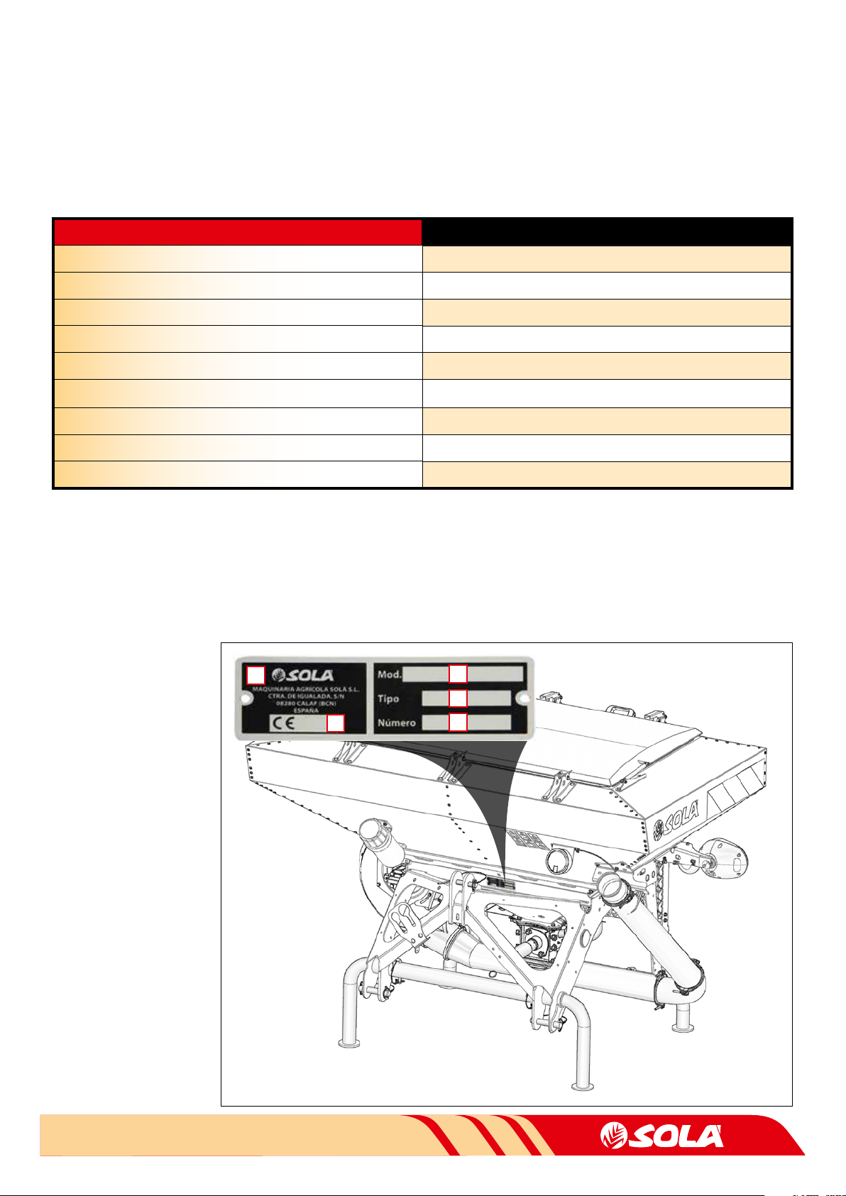
3.3 IDENTIFICATION OF THE MACHINE...........................................................................................................................................................................9
4. COMMISSIONING ............................................................................................................................................................................ 10
4.1 ASSEMBLY OF THE MACHINE TO THE TRACTOR...................................................................................................................................................10
4.2 TRACTOR'S REQUIREMENTS.....................................................................................................................................................................................10
5. DOSAGE............................................................................................................................................................................................11
5.1 DISPENSER TYPES........................................................................................................................................................................................................11
5.1.1 ROLLER DISPENSER ..........................................................................................................................................................................................11
5.1.2 ENDLESS DISPENSER........................................................................................................................................................................................12
5.1.3 TRANSFILLING DISPENSER .............................................................................................................................................................................13
5.2 CALIBRATION TEST .....................................................................................................................................................................................................13
5.3 DOSAGE GRAPHS ........................................................................................................................................................................................................14
5.3.1 ROLLER DISPENSER..........................................................................................................................................................................................15
5.3.1.1 ROLLER DISPENSER WITH A SINGLE OUTLET...................................................................................................................................15
5.3.1.2 ROLLER DISPENSER WITH TWO OUTLETS ........................................................................................................................................16
5.3.2 ENDLESS DISPENSER .......................................................................................................................................................................................17
5.3.2.1 ENDLESS DISPENSER WITH A SINGLE OUTLET................................................................................................................................17
5.3.2.2 TWO ENDLESS DISPENSERS WITH TWO OUTLETS ......................................................................................................................... 17
6. USAGE ADVICE ................................................................................................................................................................................ 18
6.1 AURA-3215 WITH PERFORMER .................................................................................................................................................................................18
6.2 AURA-3215 WITH ISOBUS..........................................................................................................................................................................................18
7. MAINTENANCE ................................................................................................................................................................................ 19
7.1 CHECK-UP FREQUENCY ..............................................................................................................................................................................................19
8. WARRANTY ..................................................................................................................................................................................... 21
SUBJECT INDEX

4

5
INTRODUCTION
1- INTRODUCTION
It is essential to read and follow the instructions and recom-
mendations in this manual before operating the presurized
hopper AURA-3215. Careful reading enables maximum opera-
tor eciency, prevents accidents and damage, and increases
the performance’s capacity and life expectancy.
Please ensure that this manual has been read by any person
involved in performing operational tasks, (including prepara-
tion, dealing with mechanical problems and supervising the
machine), maintenance (inspection and technical assistance)
and transport.
For your safety, please follow these technical safety instruc-
tions as SOLÀ will not be responsible for damages caused by
not observing the information provided.
In the rst chapters you will nd the Technical Characteristics
and Safety Instructions. Basic concepts that are required to
operate the machine are explained in the Starting, Adjusting
and Maintenance sections.
The last part of this manual consists of Dosage Graphs.
SOLÀ RETAINS THE RIGHT TO MODIFY ILLUS-
TRATIONS, TECHNICAL DATA AND WEIGHTS IN-
DICATED IN THIS OPERATING MANUAL, IF THESE
CHANGES HELP TO IMPROVE THE QUALITY OF
THE MACHINES.

6
SAFETY INSTRUCTIONS
2- SAFETY INSTRUCTIONS
2.1 SAFETY SYMBOLS
In this operating manual you will nd three dierent symbols rela-
ting to safety:
TO WORK MORE EASILY WITH THE MACHINE.
TO PREVENT DAMAGE TO THE MACHINE AND OPTIO-
NAL EQUIPMENT.
TO PREVENT PHYSICAL INJURY.
On the machine you will nd the following warning pictograms:
Read the instructions carefully and observe the safe-
ty advice given in the operating manual.
During the coupling maneuver, stay away from the
front part of the tractor. Check nobody stands in the
operational area of the telescopic folding parts.
Risk of serious physical injury.
While maintaining or repairing the planter, stop the
tractor’s engine and prevent it from starting. The ig-
nition key must be removed.
Risk of being crushed when working under the ma-
chine, please secure the machine to prevent this risk.
Risk of serious physical injuries.
It is forbidden to ride on the machine during opera-
tion. Risk of serious physical injuries caused by
falling.
Danger of infection from escaping hydraulic uid at
high pressure! This can inict serious injuries with po-
tentially fatal consequences if it passes through the
skin and into the body. Keep the hose lines in good
condition. Risk of serious physical injuries.
Do not exceed maximum load.
Coupling point for loading and unloading the machi-
ne by crane. See section 2.3 LOADING AND UNLOA-
DING INSTRUCTIONS.
2.2 GENERAL SAFETY REGULATIONS
- Before starting the machine, please check the ma-
chine is in good condition for work and is safe for
road use.
- Check that visibility is clear around the machine and
there is no person in the working area.
- In thoroughfare, please observe trac signs and re-
gulations.
- It is forbidden to ride on the machine or climb into
the machine when it is running.
- Before using the machine, the user must be familiar
with all operating elements.
- Please be extremely careful when coupling and un-
coupling the machine to the tractor.
Kg. Max.

7
SAFETY INSTRUCTIONS
- Never leave the tractor’s driver’s seat while the ma-
chine is in operation.
- Do not deposit external elements inside the hopper.
-
When maintaining the hydraulic system of the
planter, make sure that it is depressurized and the
tractor’s engine is o.
-
Please regularly check the condition of the tubes
and hosepipes in the hydraulic system. These parts
age naturally and their life should not surpass 6
YEARS. Please replace when necessary.
- During transit with the raised machine, block the
lowering switch. Before leaving the tractor, lower
the machine onto the ground and remove the
tractor’s starting key.
- Always use enough supporting elements when
maintaining the machine in a raised position to pre-
vent the machine from lowering or falling.
- Before starting to work a eld, evaluate the risks co-
ming from the terrain: pronounced slopes, possible
contact with high-voltage overhead lines due to an
uneven ground or due to the position of the mova-
ble or folding parts of the planter.
- Mount the group hydraulic multiplier only when the
tractor’s engine is o.
2.3 USE ACCORDING TO DESIGN
The AURA-3215 front hopper has been specically designed to be
used as FRONT DOSING HOPPER for seeds or fertiliser.
The machine has been designed to work using an agricultural tractor
with front lifting unity and three-point universal linkage.
If the machine is used in circumstances other than those specied
above, the manufacturer will not be held responsible for any dama-
ge caused to persons or to the machine.
The user must observe all regulations concerning safety, trac and
hygiene.
If the machine is modied by the user, the manufacturer’s warranty
is cancelled. SOLÁ will not be held responsible for any damage cau-
sed to persons or to the machine.
The use of products with a high moisture content should be avoided
since they can cause blockages.
2.4 LOADING AND UNLOADING INSTRUC-
TIONS
THESE OPERATIONS SHOULD BE PERFORMED ONLY
BY QUALIFIED AND EXPERIENCED PERSONNEL.
WHEN THE MACHINE IS DELIVERED, IT SHOULD BE
IMMEDIATELY CHECKED TO DETECT POSSIBLE DAMA-
GES DURING TRANSPORTATION OR MISSING PIECES.
ONLY THE IMMEDIATE REPORTING OF THIS TO THE
DELIVERER WILL RESULT IN COMPENSATION.
LOADING AND UNLOADING THE MACHINE MUST BE
PERFORMED, IF POSSIBLE, USING A BRIDGE CRANE.

8
100
cm de agua
40 60
20 80
0
SAFETY INSTRUCTIONS
3- GENERAL DESCRIPTION
3.1 GENERAL OVERVIEW
TRANSPORT PIPES
TURBINEDISPENSERCONTROLLER SUPPORT FEET
WORK
LIGHT BULBS
HOPPER
PRESSURIZED
TRANSPORTATION
LIGHTS
STEP TO ACCESS
HOPPER
MANOMETRO
COUPLING ACCESSORIES
TO REAR MACHINE

9
2
3
4
5
1
SAFETY INSTRUCTIONS
3.2 TECHNICAL FEATURES
3.3 IDENTIFICATION OF THE MACHINE
All machines have an
IDENTIFICATION PLATE at
the three-points, which
species:
1- Manufacturer’s name
and address.
2- Model number of the
machine.
3- Machine type.
4- Serial number.
5- CE Certicate and year
manufactured (to last
digits).
FEATURES VALUES
HOPPER CAPACITY 1.350 L
Empty weight 320 Kg
Maximum Authorized Mass (M.M.A.) 2.100 Kg
Width 2,10 m
Length 1,36 m
Height 1,62 m
Height (with optional wheels) 1,82 m
Dimensions of the ller opening 1,47 m x 0,82 m
Category of the hitch Cat. II

10
STARTING
4- STARTING
4.1
COUPLING THE MACHINE TO THE TRACTOR
The front hopper AURA-3215 is equipped with a three-point linkage
of cathegory 2.
To couple the hopper to the tractor, follow these steps:
1-
Fix the three-point linkage to the tractor using 3 bolts.
2-
Connect the hydraulic plugs to the turbine or if not feasible, con-
nect the hydraulic multiplier group to the front power take-o.
3-
Connect the 7 pin pineapple to the front electrical outlet of the
tractor.
4-
Installing the controller (as applicable):
A- ISOBUS:
1- Install and connect the cables from the front hop-
per up to the rear ISOBUS take. Turn the tractor’s
console on and download the program.
B-
PERFORMER 530:
1- Install and connect the cables from the front hop-
per up to the controller in the tractor’s cabin.
2- Install the switch in the rear duckfoot and connect
to the controller.
3- Connect the 12 VCC take from the controller to the
cabin’s take.
4- Connect the cable of the speed sign from the
tractor’s cabin take or if applicable from the exter-
nal radar.
5- Turn the controller on.
C-
NON-APPLICABLE: for translling models.
IF THE CONTROLLER DOES NOT TURN-ON, CHECK THE
CONNECTIONS.
5-
Link the rear duckfoot with the specic accessories for the front
hopper AURA-3215.
6-
Install and connect the TRANSPORT TUBES from the front hopper
up to the specic accessories of the rear duckfoot.
7-
Lift up the front hopper and put the support feet in a working
position.
IF YOU DON’T FOLD THE SUPPORT FEET DURING
TRANSPORTATION OR WORK OF THE FRONT HOPPER,
IT MAY SUFFER DAMAGES.
DURING THE TRANSPORT OF THE MACHINE CLOSE THE
CHOPPER TO PREVENT IT FROM COMPACTING THE MA-
TERIAL IN THE METERING BOX.
TRANSPORT POSITION WORK POSITION
PREVIOUS VERIFICATION:
1-
In working conditions (with the rear machine connected to the
tractor and also to the front hopper and the hopper’s top closed),
make sure that the turbine spins and the pressure indicated by the
pressure gauge is at least 40 cm of water.
2-
Verify that the dispenser’s engine spins constantly. Perform a TEST
(refer to the controller’s manual).
4.2 TRACTOR’S REQUIREMENTS
MACHINE
COMPONENT
REQUIREMENTS
TRACTOR
TURBINE Hydraulic connection with 1/2" outlet and free
3/4" return or 540 rpm front power take-o
TRANSPORTATION
LIGHTS AND WORK
LIGHT BULBS
Front plug for 7 pin pineapple
Dispensers
A.
ISOBUS Connection or 12 vcc connection to
cabin (for dispensing)
B. Front 12 vcc intake
THREE-POINT FRONT THREE-POINT LINKAGE
Frame and scheme of the 7 pin connector:
1
5
4
7
6
3
2
Pin Number FUNCTION Intensity (A)
1Left intermittent 2
2Short lights 6
3Mass -
4Right intermittent 2
5Position lights 1
6Long lights 8
7Work headlights 2,5

11
DOSAGE
5- DOSAGE
5.1 DISPENSER TYPES
The machine may be congured with 3 types of dispensers:
1-
ROLLING dispenser (for dosage or translling)
2-
ENDLESS dispenser (only for dosage)
3-
TRANSFILLING dispenser (only for translling)
In this subject, you will nd symbols to distinguish the congura-
tions required to dose or transll a product to the rear duckfeet:
DOSAGE
TRANSVASE
5.1.1 ROLLING DISPENSER
Depending on the type of connection accessories installed in the rear
duckfeet, this dispenser will be able to DOSE or TRANSFILL seeds or
fertilizer.
The following congurations exist:
- A rolling dispenser with an outlet.
- A rolling dispenser with two outlets.
IMPORTANT: DEPENDING ON THE WORK AND INS-
TALLATION CONDITIONS, THE DISPENSER SYSTEM IS
CAPABLE OF WORKING UP TO 180 Kg/Ha WITH AN OUT-
LET OF Ø80, AND UP TO 250Kg/Ha WITH AN OUTLET
OF Ø120 (WORK WIDTH CONSIDERED IS OF 6 METERS).
TO PERFORM SEED TRANSFILLING WITH THIS ROLLING
DISPENSER, YOU MUST CONFIGURE IT WITH 7 SECTORS,
IN WHICH CASE IT SHALL BE ABLE TO ACHIEVE VALUES
CLOSE TO 42 Kg/min
DEPENDING ON WORK AND INS-
TALLATION CONDITIONS
.
This dispenser has a roller that may be congured in sectors. 1 to
7 sectors may be set-up. The sectors may be; simple (one sector) or
triple (three sectors).
SIMPLE SECTOR
TRIPLE SECTOR
This dispenser should be congured and adapted to the desired
dose, to achieve that follow the following steps:
1-
See the dosage graphs to determine the number of rolling sectors
required for the desired dose (refer to 5.3 DOSAGE GRAPHS).
2-
Pull out latch “R”.
3- Take the two screws out.
4-
Pull out the side support and extract the roller.

12
DOSAGE
5-
Congure the number of sectors required depending on the de-
sired dose, to modify the conguration of the sectors, the seeger
ring must be pulled-out, set-up the sectors as per the dosage gra-
ph images and put the seeger ring back in place.
4 SECTORS 1 SECTOR
6-
Reassemble the roller, side support and set in place with the two
screws.
MAKE SURE THE SEEGER RINGS ARE WELL PLACED
IN THEIR HOUSING, SO THAT THESE CAN BE TURNED
AROUND.
WHEN EXTRACTING THE ROLLER, MAKE SURE NOT TO
LOSE THE O-RINGS OF THE AXLE (SMALL) AND SIDE
SUPPORT (BIG), PUT THE RINGS BACK TOGETHER CO-
RRECTLY WHEN ASSEMBLING THE ROLLER.
LARGE JOINT
SMALL JOINT
DON’T FORGET THE LATCH “R” OR THE DISPENSER
WON’T WORK.
5.1.2 ENDLESS DISPENSER
This dispenser only works for DOSAGE of micro-granulated fertilizers
in low doses.
You may switch the endless of this dispenser to adapt it to the desired
dose, and in order to do that follow the following steps:
1-
See the following dosage graphs to determine the correct endless
for the desired dose (refer to 5.3 DOSAGE GRAPHS).
2-
Pull out latch “R”.
3- Loosen the two locking handles.
4-
Pull out the lower support and extract the endless.
5-
Mount the corresponding endless depending on the previously
selected graph.

13
DOSAGE
WHEN EXTRACTING THE ENDLESS, BE CAREFUL NOT
TO LOSE THE O-RINGS OF THE AXLE. MOUNT THE O-
RING CORRECTLY AFTER ASSEMBLING THE ENDLESS.
DON’T FORGET THE LATCH “R” OR THE DISPENSER
WON’T WORK.
5.1.3 TRANSFILLING DISPENSER
This dispenser only works as TRANSFILLING of seed or fertilizer in low
doses (20 Kg/min).
5.2 CALIBRATION TEST
Before working with the machine, a ow test must be performed in
order to determine the dose to be distributed. For that, you must:
1-
Assembly the distributor’s roller or change the endless, in function
of the chosen dosage graph.
2-
Place the chopper in working position.
CLOSED POSITION WORK POSITION
3-
Open the calibration cap acting over the 2 closures.
4-
Put the supplied sack or any other container below the calibration
output.
5-
Act over the PERFORMER or ISOBUS controller of the machine to
perform the test, see specic PERFORMER or ISOBUS manual.
6-
Weigh the material in the sack or container and verify that it’s the
desired dose, if not increase or decrease the dose through the
controller or by changing the number of sectors of the roller or
endless (depending on the model).
WHENEVER THE DISTRIBUTOR’S CONFIGURATION IS
MODIFIED OR PRODUCTS ARE SWITCHED, YOU MUST
PERFORM A CALIBRATION TEST.
THE CONTROLLER’S SCREEN HAS A BAR THAT INDICA-
TES THE ENGINE’S LOADING RANGE. IT MUST WORK
WITHIN 60% TO 80% OF ITS CAPACITY.
60%- 80%
WHEN FINISHING THE CALIBRATION TESTS, CLOSE
THE CALIBRATION CAP AGAIN.

14
DOSAGE
5.3 DOSAGE GRAPHS
The dose per hectare that may be supplied by the dispenser de-
pends on the number of sectors and type of endless. To nd the
dosage values you must:
1-
Recalculate the value of the Kg/Ha in order to enter the graphs
(value <X>), by using the following formula
X =6
A LIGHT BULBS
K x
WHERE:
K= Kg/ha desired to dose.
A LIGHT BULBS = Work width in meters.
X = Recalculated value in Kg/ha to enter the graphs.
2-
With the recalculated value of the dose in Kg/Ha and the working
speed in Km/h, enter it in the graphs were the intersection point is
between the MAXIMUM and MINIMUM dosage curves.
EXAMPLE:
For a rear machine with work width of 4,5 meters, a desi-
red dosage of 120 Kg/Ha and a work speed of 8 Km/h.
Step 1-
Recalculate the dose <X>:
X =6
4,5
120 x= 160 Kg/Ha
Step 2-
With the value of 160 Kg/Ha and a work spe-
ed of 8 Km/h enter the graphs:
0
50
100
150
200
6 8 10 12 14
DOSIF. kg/ha
VELOCIDAD km/h
MÁXIMA Y MÍNIMA DOSIFICACIÓN
MÁX. MÍN.
2 SECTOR GRAPH
0
50
100
150
200
250
6 8 10 12 14
DOSIF. kg/ha
VELOCIDAD km/h
MÁXIMA Y MÍNIMA DOSIFICACIÓN
MÁX. MÍN.
3 SECTOR GRAPH
THE AMOUNTS INDICATED WITHIN THE GRAPHS
MUST BE CONSIDERED AS ORIENTATION ESTIMA-
TIONS AS THE PROVIDED FLOW MAY VARY DUE TO
THE PRESENCE OF DUST, SIZE OF THE PRODUCT TO BE
USED, DENSITY, HUMIDITY, ETC.
BEFORE STARTING TO WORK, PERFORM A TEST TO
CALIBRATE IT. IN ORDER TO DO THAT, REFER TO THE
CONTROLLER’S MANUAL FOR PERFORMER 530 OR IS-
OBUS (DEPENDING ON THE MODEL).
THE CONTROLLER’S SCREEN HAS A BAR THAT INDICA-
TES THE ENGINE’S LOADING RANGE. IT MUST WORK
WITHIN 60% TO 80% OF ITS CAPACITY.
60%- 80%
THE DOSAGE GRAPHS ARE FOR MACHINES WITH A
WORKING WIDTH OF 6 METERS FOR MACHINE MO-
DELS WITH ROLLER DISTRIBUTORS AND ENDLESS.
DOSAGE GRAPHS CONSIDER A PRODUCT WITH
DENSITY 1,056 Kg/L FOR FERTILIZER WITH DIS-
TRIBUTOR TO ROLLER TO BE APPLIED IN REAR MA-
CHINE WITH DISTRIBUTOR HEAD WITHOUT SEED
LOAD.
DOSAGE GRAPHS CONSIDER A PRODUCT WITH
DENSITY 0,956 Kg/L FOR MICRO-GRANULATED
FERTILIZER WITH DISTRIBUTOR TO ENDLESS TO
BE APPLIED IN REAR MACHINE WITH DISTRIBUTOR
HEAD WITHOUT SEED LOAD.

15
0
100
200
300
400
6 8 10 12 14
DOSIF. kg/ha
VELOCIDAD km/h
MÁXIMA Y MÍNIMA DOSIFICACIÓN
MÁX. MÍN.
0
50
100
150
200
250
6 8 10 12 14
DOSIF. kg/ha
VELOCIDAD km/h
MÁXIMA Y MÍNIMA DOSIFICACIÓN
MÁX. MÍN.
0
20
40
60
80
100
6 8 10 12 14
DOSIF. kg/ha
VELOCIDAD km/h
MÁXIMA Y MÍNIMA DOSIFICACIÓN
MÁX. MÍN.
0
50
100
150
200
6 8 10 12 14
DOSIF. kg/ha
VELOCIDAD km/h
MÁXIMA Y MÍNIMA DOSIFICACIÓN
MÁX. MÍN.
DOSAGE
Kg/Ha
Km/h
Kg/Ha
Km/h
3 SECTORS
4 SECTORS
Kg/Ha
Km/h
Kg/Ha
Km/h
1 SECTOR
2 SECTORS
5.3.1 ROLLER DISPENSER WITH A SINGLE OUTLET
5.3.1.1 ROLLER DISPENSER WITH A SINGLE OUTLET

16
0
100
200
300
400
6 8 10 12 14
DOSIF. kg/ha
VELOCIDAD km/h
MÁXIMA Y MÍNIMA DOSIFICACIÓN
MÁX. MÍN.
0
50
100
150
200
6 8 10 12 14
DOSIF. kg/ha
VELOCIDAD km/h
MÁXIMA Y MÍNIMA DOSIFICACIÓN
MÁX. MÍN.
DOSAGE
5.3.1.2 A ROLLER DISPENSER WITH TWO OUTLETS
Kg/Ha
Km/h
Kg/Ha
Km/h
1+1 SECTORS
2+2 SECTORS

17
0
20
40
60
80
100
6 8 10 12 14
DOSIF. kg/ha
VELOCIDAD km/h
MÁXIMA Y MÍNIMA DOSIFICACIÓN
MÁX. MÍN.
0
5
10
15
20
25
30
6 8 10 12 14
DOSIF. kg/ha
VELOCIDAD km/h
MÁXIMA Y MÍNIMA DOSIFICACIÓN
MÁX. MÍN.
0
50
100
150
200
6 8 10 12 14
DOSIF. kg/ha
VELOCIDAD km/h
MÁXIMA Y MÍNIMA DOSIFICACIÓN
MÁX. MÍN.
0
10
20
30
40
50
60
6 8 10 12 14
DOSIF. kg/ha
VELOCIDAD km/h
MÁXIMA Y MÍNIMA DOSIFICACIÓN
MÁX. MÍN.
DOSAGE
5.3.2 ENDLESS DISPENSER
5.3.2.1 AN ENDLESS DISPENSER WITH A SINGLE OUTLET
Kg/Ha
Km/h
Kg/Ha
Km/h
1 endless
SMALL
38 cm3
1 endless
LARGE
75 cm3
5.3.2.2 TWO ENDLESS DISPENSERS WITH TWO OUTLETS
Kg/Ha
Km/h
Kg/Ha
Km/h
2 endless
SMALL
2x38 cm3
2 endless
LARGE
2x75 cm3

18
TIPS FOR USE
6- TIPS FOR USE
6.1 AURA-3215 WITHOUT ISOBUS
1- Forward speed:
To obtain a uniform work, keep the forward speed without sudden
stops, since variations in forward speed modify the amount of pro-
duct applied on the ground.
To put attention when starting and stopping the tractor:
-
When STARTING, the air circuit is empty and the machine
will not work until it has run some metres.
-
When
STOPPING
, It is recommended to cut the dosing a
few meters before stop.
2- Check product’s ow:
Perform a previous calibration test in the warehouse in order to
know exactly the amount of product going to be spread. Dosage is
going to be very dierent when using dierent kinds of product, as it
depends on factors such as density, moisture content, etc..
3- Distance between tramlines:
Keeping the distance between tramlines is essential to get opti-
mal distribution.
6.2 AURA-3215 CON ISOBUS
1- Advancing speed:
Activate mode <PRESTART>. In this mode, dosage errors during
start-up and shut-down of the tractor will be minimized. For that see
specic manual for the MULTIPERFORMER ISOBUS.

19
MAINTENANCE
7- MAINTENANCE
IN CASE OF MALFUNCTION, STOP THE PLANTER IM-
MEDIATELY AND REMOVE THE IGNITION KEY. LEAVE
THE TRACTOR AND VISUALLY INSPECT AND EVALUA-
TE THE EXTENT OF THE PROBLEM. PERFORM THE
REQUIRED OPERATIONS ON THE PLANTER BEFORE
RESTARTING IT.
MAINTENANCE OPERATIONS MUST BE PERFORMED
IN PROPERLY EQUIPPED GARAGES BY QUALIFIED PER-
SONNEL.
NO REPAIRS SHOULD BE PERFORMED WITHOUT THE
NECESSARY SKILLS AND KNOWLEDGE. IT IS ESSEN-
TIAL THAT THE INSTRUCTIONS DETAILED IN THIS
MANUAL ARE STRICTLY FOLLOWED. IF THESE INS-
TRUCTIONS ARE MISSING, PLEASE CONTACT THE
PLANTER’S PROVIDER OR QUALIFIED PERSONNEL.
IN ORDER TO PERFORM MAINTENANCE OR REPAIR
OPERATIONS TO THE PLANTER, IT IS ESSENTIAL TO
USE PROPER PERSONAL PROTECTIVE EQUIP-
MENT (PPE): SAFETY BOOTS AND GLOVES, HEARING
PROTECTION, DUST MASK AND PROTECTIVE GLAS-
SES).
IT IS RECOMMENDED TO AVOID WEARING LOOSE
CLOTHING SINCE IT MAY BECOME TANGLED WITH
THE PLANTER’S MOVING PARTS.
Before performing any task on the machine, it is essential to take into
account the following factors:
- Maintaining or repairing the planter should be performed on a
at and compact ground. Before starting any of these tasks, the
tractor’s engine must be turned o and the ignition key removed.
- The chosen device to raise the planter needs to be appropriate for
the operations to be performed. Please ensure that all safety regu-
lations are observed.
- Always use appropriate protective equipment for any task to be
performed.
- In case compressed air is used to clean the planter, you are required
to wear protective glasses and mask.
- If any operation needs to be performed on a part of the machine
which is at more than 1,5 metres height from the ground, check if it
is possible to reach this part using the planter’s access points. If not
possible, use either a ladder or a platform which is in accordance
with the current safety regulations.
- Prolonged and/or repetitive skin contact with fuel and lubricants
is harmful. In case these products come accidentally into contact
with the eyes or other sensitive parts, wash well the aected parts
with clean water. In case of ingestion, contact the medical services
immediately.
7.1 CHECKING FREQUENCY
The periodicity of the check-ups indicated below is solely for orien-
tation purposes. It may suer variations depending on the type of
service, use of the machine and conditions of use.
- BEFORE STARTING THE SOWING SEASON:
Check the general operation of the planter. Perform this check
without any products inside the hopper.
Check that the plastic components of the planter are in good condi-
tion. The wear of this material due to natural ageing or to the presen-
ce of rodents causes damages to these components.
Check that the mechanical components are in good condition and
not rusty.
Clean the parts of the machine which are permanently in contact
with seeds or fertilizers, such as hopper and metering unit.
Check that the signal lamps work properly.
Check that the unions and the ducts of the hydraulic system do not
show oil leaks.
- DAILY:
Empty and clean with air pressure both the hopper and the dispen-
ser of residual products that may remain after nishing the work
shift.
Check that the metering unit and the air circuit do not contain any
residue (such as seed or fertilizer residue, dust, etc). Residue accumu-
lation may damage the air circuit.
- END OF SOWING SEASON
Empty and clean with air pressure both the hopper and the dispen-
ser, making sure that there are no residual products,
If washing the machine, make sure no residual products remain, as
they may damage the machine if left to dry.
Repaint any metallic component which has lost its paint due to wear.
To store the planter properly, cover it with tarpaulin and keep it in a
dry place.
Thoroughly check all components of the planter and replace the
ones which are damaged or worn.
A careful maintenance of the machine ensures proper functioning
and long service life of the machine.
BEFORE PERFORMING THESE OPERATIONS, THE
PLANTER’S ENGINE MUST BE TURNED OFF AND THE
IGNITION KEY REMOVED.
The next table shows the maintenance operations to be performed
on the machine along with their (GUIDANCE) frequency:
AFTER THE FIRST 10 HOURS OF WORK, TIGHTEN THE
SCREWS.

20
MAINTENANCE
INTERVENTION AREA OPERATION TO BE PERFORMED
DAILY
WEEKLY
ANNUAL
Road lights and signs
Check light conditions and functioning ●
Make sure that the safety adhesives are in place and readable ●
Hydraulic components
Check the condition of the hoses and hydraulic connectors, make sure there are no leaks ●
Check the oil lter status (only for turbines with an independent hydraulic circuit) ●
Pneumatic system
Clean the dirt from the turbine's protective grille and check its condition ●
Check the condition of the spinning state of the turbine ●
Check the condition of the pipes and replace those that have cracks ●
Rubber components and plastic
pieces Check its deterioration and if required replace the damaged components ●
Screws Check the condition of the screws. Tighten all screws and bolts ●
Endless dispenser Clean the dispenser, don't leave any residual material ●
Roller dispenser Clean and check the status of the roller and sealing lip, don't leave any residual material ●
Table of contents
Popular Tractor Accessories manuals by other brands

Erskine Attachments
Erskine Attachments 68 Operator's manual

Craftsman
Craftsman 486.245451 owner's manual

Camoplast
Camoplast Tatou UTV T4S Installation guidelines

Tektite
Tektite Massey GC1725M ROPS Cab Operator's manual

AGI
AGI WHEATHEART X130 Operator and Assembly Manual

Avantco
Avantco A36841 Operator's manual for Attachment