Solaira Alpha H3 User manual

EN
Reference Manual
Solaira Alpha
H3 277V
(3 × Lamp Emitter Heater)
CANADA & USA MODELS:
WEATHERPROOF INFRARED HEATERS SUITABLE FOR OUTDOOR AND INDOOR USE
IN NON-HAZARDOUS AREAS
- COMMERCIAL AND INDUSTRIAL, (RESIDENTIAL 240V OUTDOOR USE ONLY)
Ref No. 043484-EN-S Iss. A
I M P OR TA N T - S AV E T H E S E I N S T R U C T I O N S F O R F U T U R E R E F E R E N C E
INFORESIGHT CONSUMER RODUCTS INC.
125 Traders Blvd. E Unit # 4, Mississauga, Ontario L4Z 2H3
Tel 905-568-7655 - Fax 905-568-7521
Email info@solairaheaters.com - Website www.solairaheaters.com
247748
SALPHA -45277C (240V - 75W / 277V - 4500W)
SALPHA -45277L1C (240V - 75W / 277V - 4500W) CANDEL LOW LIGHT
SALPHA -60277C (240V - 4500W / 277V - 6000W)
SALPHA -60277L1C (240V - 4500W / 277V - 6000W) CANDEL LOW LIGHT
C = COLOR CODE
1. Read all instructions before using this heater.
2. Use this heater only as described in this manual. Any other use not
recommended by the manufacturer may cause fire, electric shock, or
injury to persons.
3. This heater is hot when in use. To avoid burns, do not let bare skin
touch hot surfaces. If provided, use handles when moving this heater.
Keep combustible materials, such as furniture, pillows, bedding,
papers, clothes, and curtains at least 6 feet (1.8m) from the front of the
heater and keep them away from the sides and rear.
4. Extreme caution is necessary when any heater is used by or near
children or invalids and whenever the heater is left operating and
unattended.
5. Do not operate any heater with a damaged cord or after the heater
malfunctions, has been dropped or damaged in any manner. Return
heater to authorized service facility for examination, electrical or
mechanical adjustment, or repair.
6. This heater is not intended for use in bathrooms, laundry areas and
similar locations. Never locate heater where it may fall into a bathtub
or other water container.
7. To disconnect heater, turn controls to off.
WARNING -
Each power supply circuit shall be provided with
disconnecting means and the disconnecting means shall be grouped
together.
I M P O R TA N T I N S T RU C T I O N S
When using electrical INFRARED HEATERS, basic precautions
should always be followed to reduce the risk of fire, electric shock,
and injury to persons, including the following
2 of 16 Ref No. 043484-EN-S Iss. A

8. Do not insert or allow foreign objects to enter any opening as this may
cause an electric shock or fire, or damage the heater.
9. To prevent a possible fire, do not block openings in any manner.
10. A heater has hot parts inside. Do not use it in areas where gasoline,
paint, or flammable liquids are used or stored.
11. Do not cover or otherwise obstruct the heater.
I M P O R TA N T I N S T RU C T I O N S
SAVE THE SE I NST RUCTI ON S
G R O U N D I N G I N S T R U C T IO N S
For 240V / 277V heaters, the cords from each terminal box must be
permanently connected (hard wired).
Kee combustible material such as furniture, a ers,
clothes and curtains at least 6 feet (1.8m) from the front
of the heater and away from the sides and rear.
Heaters are not intended for use as indoor residential or
as a household heater. They may be used for outdoor residential
240V use.
WAR N I NG : R I S K O F F IRE
3 of 16 Ref No. 043484-EN-S Iss. A
I N T R O D U C T I O N
The Alpha H3 heater produces radiant heat like the sun, warming people and objects rather
than the air in between. It is mounted on an adjustable bracket that allows the heat to be
directed exactly where it is required. The Alpha H3 can also be used in a modular system in
that more than one heater can be connected together - see ‘Configurations’ later in the
manual. The Alpha H3 weatherproof heater is designed for indoor and outdoor use.
Please read the following instructions carefully before use. The safety of this heater is
guaranteed only by its correct usage in accordance with these instructions, therefore
they should be retained for future reference.
Before using this appliance
1. Check that the voltage indicated on the units rating label corresponds to the mains
supply voltage.
2. Do not install the heaters less than the minimum height from the floor as specified below
in the specification table.
3. Ensure that the heater has been securely fastened in its final mounting position.
4. WARNING - This appliance must be grounded and hard wired!
5. WARNING - Keep the supply cables away from the front and body of the heater which
will get hot during use.
6. Do not cover or obstruct the heater while it is in use.
7. Do not insert any object through any slot or opening in the heater.
8. Do not use if a grille is not present.
9. When replacing the emitter or cleaning the unit, ensure that the hard wired circuit(s) is
disconnected from the mains supply. Note: always ensure that the lamp emitter is cool
before handling.
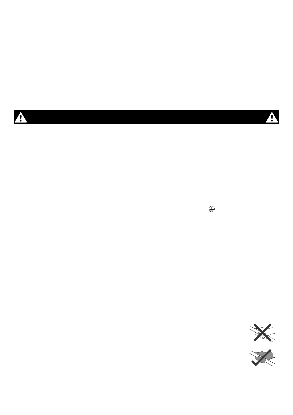
10. Do not handle the halogen emitter with bare hands. If it is inadvertently
touched, remove finger marks with a soft cloth and methylated spirit or
rubbing alcohol. Otherwise, the marks will burn into the quartz glass of the
lamp emitter during use causing premature heater failure.
11. The heater is not intended for use by young children and must be supervised
by a responsible person at all times.
C AU T I O N
4 of 16 Ref No. 043484-EN-S Iss. A
5 of 16 Ref No. 043484-EN-S Iss. A
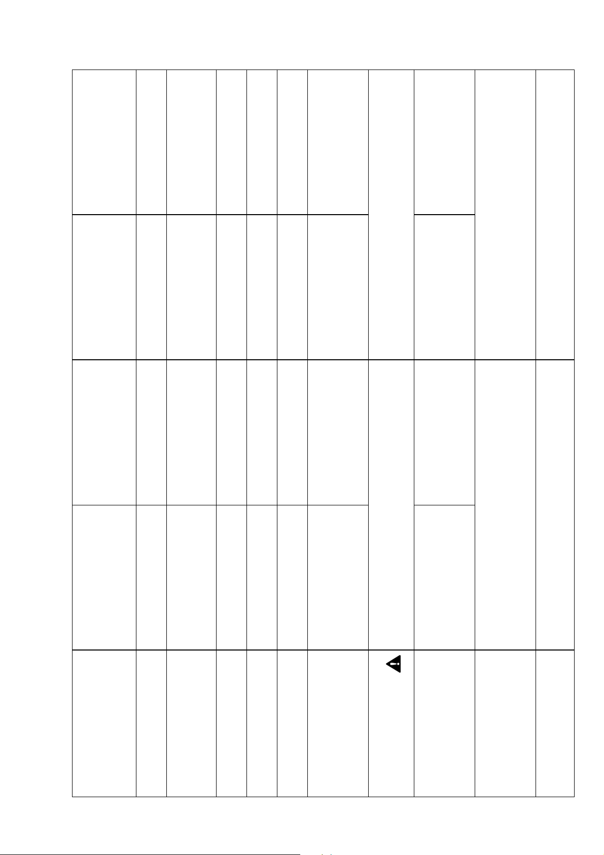
S P E C I F I C AT I O N TA B L E
A l h a H 3 2 4 0 V / 2 7 7 V H e a t e r s
Number of
Units
Model Type
1 - off
SALPHA3-45277C
or
SALPHA3-45277L1C
1 - off
SALPHA3-60277C
or
SALPHA3-60277L1C
2 - off
SALPHA3-45277C
or
SALPHA3-45277L1C
2 - off
SALPHA3-60277C
or
SALPHA3-60277L1C
Voltage 240V /277V 240V /277V 240V /277V 240V /277V
Number of 3 3 6
6
Lamp Emitters
Power
1125W /1500W 1500W /2000W 1125W /1500W 1500W /2000W
Total Power
of Unit 3375W /4500W 4500W /6000W 6750W /9000W 9000W /12000W
Current er
Lam Emitter 4.7A /5.4A 6.3A /7.2A 4.7A /5.4A 6.3A /7.2A
Total Current
of Unit 14.1A /16.2A 18.8A /21.7A 28.1A /32.5A 37.5A /43.3A
Minimum Mounting
Height from Floor/
Grade to Bottom of
Heater
7ft 10½in
(240 cm)
/
8ft 2in
(249cm)
8ft 9in
(267cm)
/
9ft 6in
(290cm)
9ft 9in
(297cm)
/
11ft
(330cm)
Minimum Distance
from Ceiling to To
of Heater
7½in
(19cm)
15in
(38cm)
Minimum Distance
from Side Wall to Side
of Heater
36in
(92cm)
/
33in
(84cm)
34in
(86cm)
/
39in
(99cm)
43in
(109cm)
/
49in
(124cm)
51in
(130cm)
/
59in
(150cm)
Dimensions -
W × H × D
(inc. Bracket &
bars in max. osition)
47½in × 9in × 12¾in
(120cm × 23cm × 32cm)
47½in × 18¼in × 12¾in
(120cm × 46cm × 32cm)
Weight 17.6lb
(8.0kg)
35.4lb
(16.5kg)
7ft 10½in
(240 cm)

6 of 16 Ref No. 043484-EN-S Iss. A
I N S TAL L AT I O N
The heater is fitted with 3 × supply cords measuring 79in (200cm) for hard wiring.
WARNING: Wiring procedures and connections should be in accordance with the National
Electric Code (NEC) and local codes.
WARNING: If the supply cord(s) becomes damaged, it must be immediately replaced by a
qualified person in order to avoid a hazard.
CAUTION: Disconnect electric power supply before working on circuit wiring to prevent electric
shock.
CAUTION:
Please observe the minimum safe distance between the heater body and any
inflammable surfaces.
CAUTION: When the electrical connection is outside weatherproof sockets must be used having
ground fault protection (GFCI or GFI).
NOTE: CONSULT A QUALIFIED ELECTRICIAN, IF IN DOUBT.
!
C O N F I G U R AT I O N S
The Alpha H3 heater contains three lamp emitters. It can be installed as a single unit or
joined to one other single unit with joining bars that are available to connect the heaters
together and increase the size and output of the installation. The maximum number of Alpha
H3 heaters that can be joined together is two. Please read the section ‘joining heaters
together’ for information on how this should be done.
The Alpha H3 heater should only be wall
mounted in a horizontal manner or hung from
a ceiling from chains (not supplied).
When wall mounting the Alpha H3 heater, do
not position the heater at an angle more than
50° and less than 30° as shown in Fig. A.
When ceiling hanging the Alpha H3 heater,
ensure the minimum distance from the
ceiling is adhered to as shown in Fig. B.
continue over page…
M O U N T I N G - 1 × T R I P L E ( T H R E E L AM P E M I T T E R ) H E AT E R
C A U T I O N
Always isolate the heater from the mains
su ly when mounting or adjusting the
heater osition.
Fig. A
SEE
SPEC.
TABLE
FOR MIN.
HEIGHT

7 of 16 Ref No. 043484-EN-S Iss. A
Always allow the heater to cool before attempting to
reposition/move. Never attempt to move the heater
while it is switched on!
Observe the minimum safe distance between the heater
body and inflammable surfaces and objects when
mounting.
Please refer to the specification table for the
recommended positioning of the heater with regards to
minimum distances. Do not install the heater in a
corner!
Keep out of the reach of children.
1. When wall mounting, securely fasten the L-shaped
wall brackets to the mounting surface using both of the
fixing holes in the short part of the bracket (see Fig. D for
mounting hole centres). Please refer to the specification
table for recommended positioning of the heater. Please
note. wall fixings are not supplied. They should be
selected to substantially support the weight of the
installation. If in doubt contact a professional for advice!
When hanging from a ceiling two equal length and gauge
chains are required and should be selected with fixings
that are adequate to hold the weight of the heater. Again,
if in doubt contact a professional for advice!
2. The heater should be mounted with the terminal box
at the bottom of the heater when being wall mounted.
3. When wall mounting, fix in the required angular
position by tightening the fixing bolts on the brackets at
the rear of the heater as shown in Fig. C. The heater
should face directly down when hanging.
4. Secure the supply cable so it is not resting on the
body or obstructing the air-vents.
Always isolate the heater from the mains su ly when
adjusting the osition.
DRILLING HOLE TEMPLATE DIMENSIONS FOR WALL MOUNTED BRACKETS
Fig. D
Fig. B
Fig. C
TERMINAL
BOX
SEE SPEC.
TABLE
FOR MIN.
CLEARANCE
Fig. B
8 of 16 Ref No. 043484-EN Iss. A
AS S E M B L I N G -
2 × T R I P L E ( T H R E E L A M P E M I T T E R ) H E AT E R S J O I N E D
1. Take the first heater and place it face down on a flat surface.
2. Take the second heater and place it face down and positioned parallel to the first heater.
3. Push the bolts used to hold the wall brackets through the hole in the brackets on the rear
heaters and slide a shake-proof washer on all the threads from the protruding side.
4. Slide the joining bars on each bolt and fit a washer and nut – do not fully tighten at this
point.
5. Ensure the second heater is still parallel to the first and sitting flat.
6.
Slide the joining bars on each protruding bolt of the other heater to connect them
together and fit the washers and nuts.
7. Again, ensuring the heaters remain flat, fully tighten all four nuts to secure the joining
bars in place.
When two Alpha H3 heaters are joined they should only be hung from a ceiling on
chains - do not wall mount!
Always allow the heater to cool before attempting to reposition/move. Never attempt to
move the heater while it is switched on!
Observe the minimum safe distance between the heater body and inflammable
surfaces and objects when mounting.
Please refer to the specifications table for the
recommended positioning of the heater with
regards to minimum distances. Do not install the
heater in a corner!
Keep out of the reach of children.
1. When hanging from a ceiling, two chains of
equal length and gauge are required and should
be selected with fixings that are adequate to
hold the weight of the heater. If in doubt contact
a professional for advice!
Continue on next page...
C A U T I O N
Always isolate the heater from the mains su ly when mounting or adjusting the
heater osition.
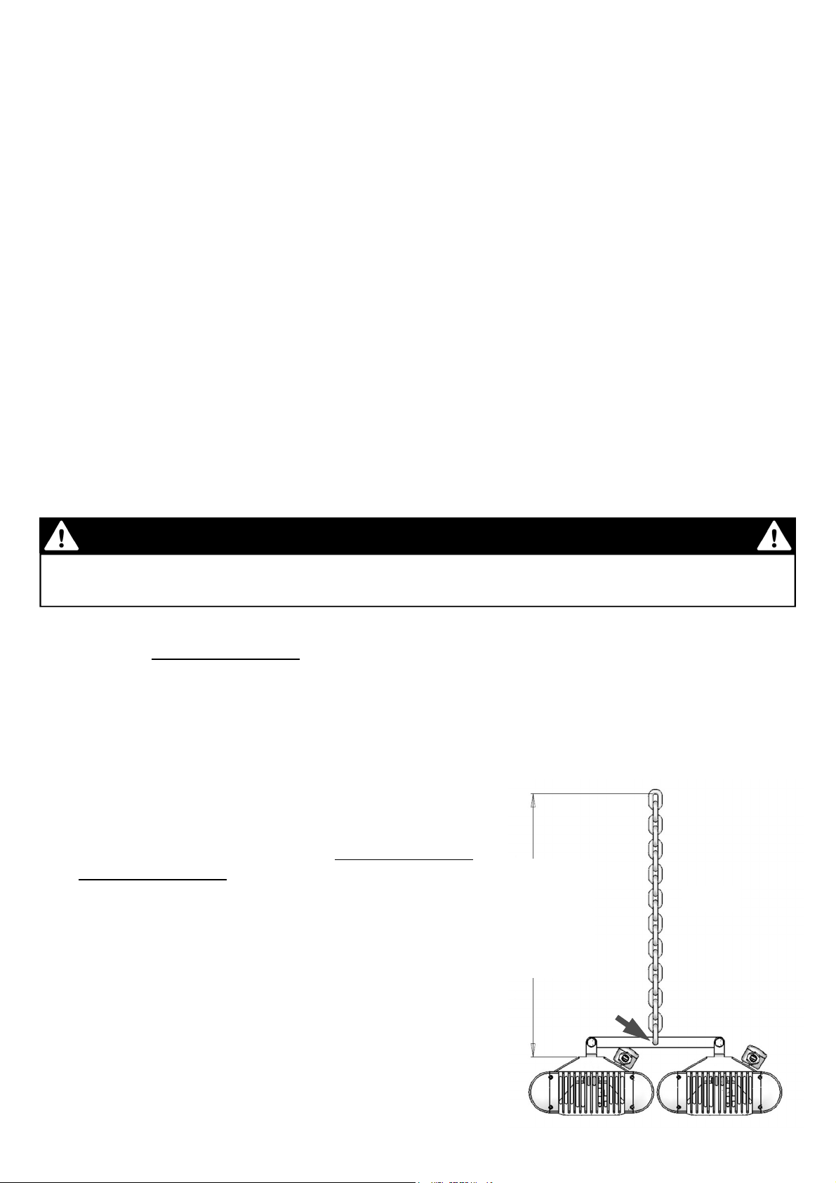
C H AI N H AN G IN G -
2 × T R I P L E ( T H R E E L AM P E M I T T E R ) H E AT E R S J O I N E D
Fig. E
SEE
SPEC.
TABLE
FOR MIN.
CLEARANCE
9 of 16 Ref No. 043484-EN-S Iss. A
2. Fix the heater assembly to the chains via the hole in the centre of the joining bar as
shown in Fig. E. and ensure the heaters face directly down when hanging.
3. Secure the supply cable so it is not resting on the body or obstructing the air-vents.
Always isolate the heater from the mains su ly when adjusting the osition.
Fig. F
Fig. G
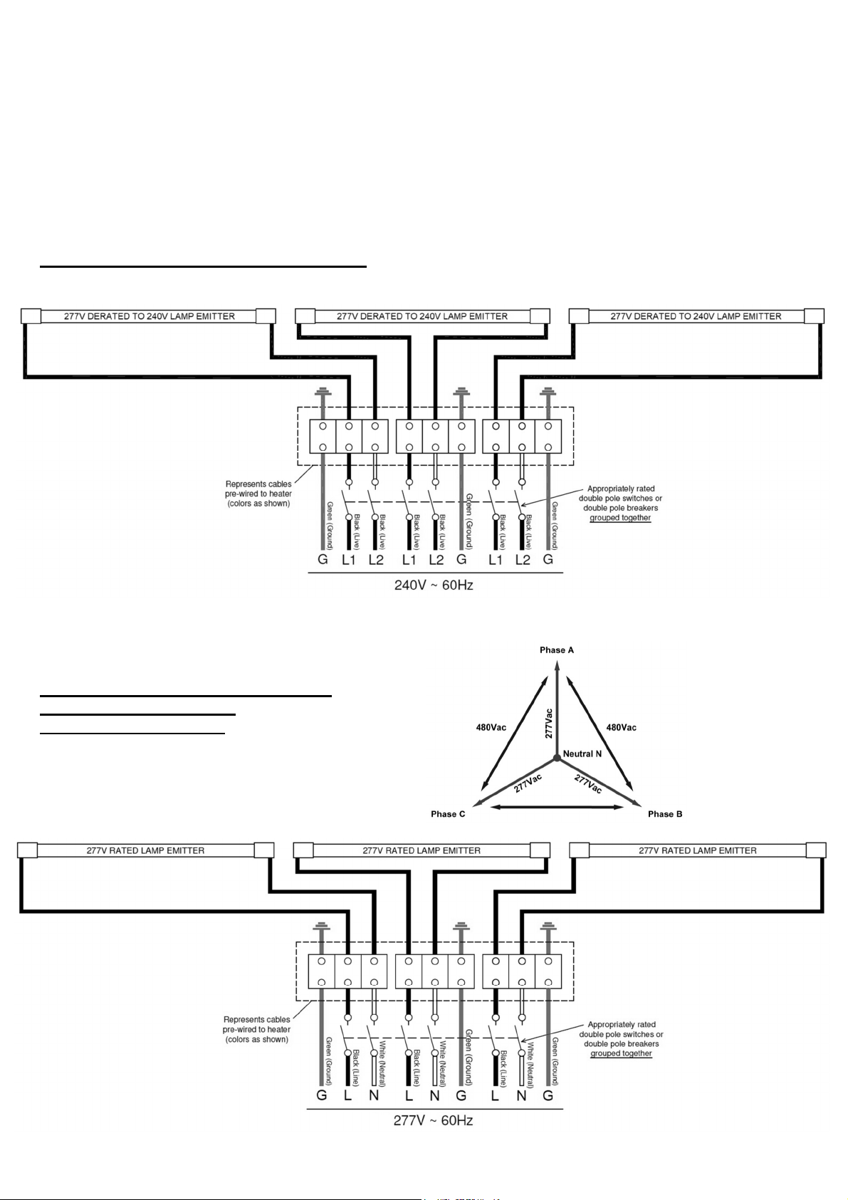
C I R C U I T D I A G R AM 2 4 0 V S U P P LY
277V HEATER RATED ON 240V SUPPLY
277V RATED HEATER CONNECTED
ON STAR/WYE OUTPUT
(NEUTRAL TO PHASE)
C I R C U I T D I A G R AM 2 7 7 V S U P P LY
10 of 16 Ref No. 043484-EN-S Iss. A
M AI N T E N AN C E ( 2 7 7 V C I R C U I T )
CAUTION: Unplug/Switch off unit from the mains supply before replacing a lamp emitter
or any maintenance procedure including cleaning.
CAUTION: Should dust or dirt appear on the reflectors, it is recommended that that the
wire grilles and lamp emitters are removed and the reflectors are wiped with a lint-free
cloth before reassembling (see lamp emitter replacement instructions).
NOTE: For re lacement lam emitters or s are arts lease contact your local
distributor quoting model ty e and rating from rating label. It is very im ortant that
your re lacement lam emitters are exactly the same as the one it was su lied
with. Failure to fit the exact same ty e can cause the heater to rematurely fail.
!
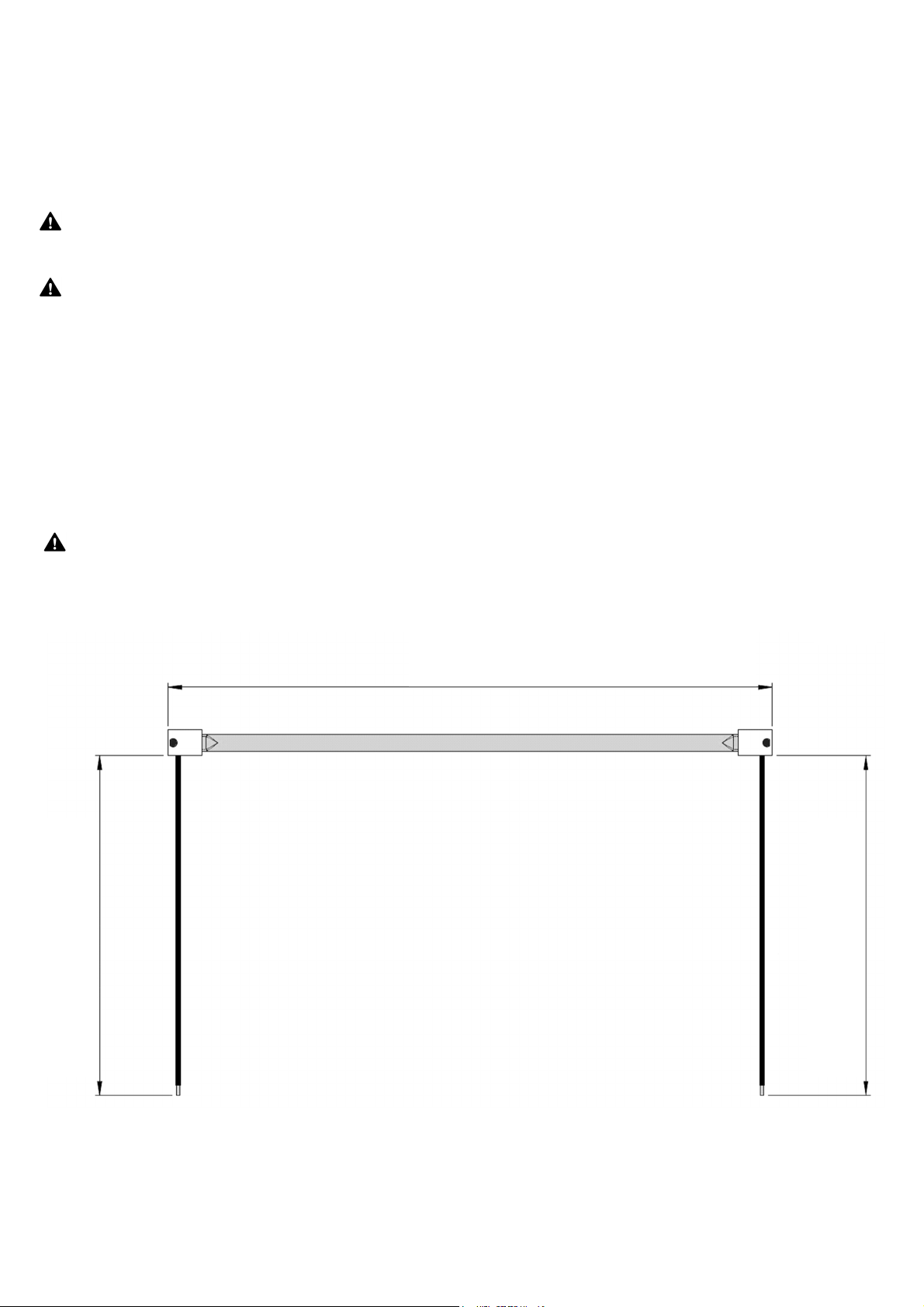
CAUTION: Please ensure that the length of wires on the replacement lamp emitter are the same
as shown in the diagram below (Fig. H).
Y O U R R E P LA C E M E N T L A M P E M I T T E R
Fig. H
[13.976in]
355mm MAX.
[17.976in]
375mm MAX.
[17.976in]
375mm MAX.
11 of 16 Ref No. 043484-EN-S Iss. A
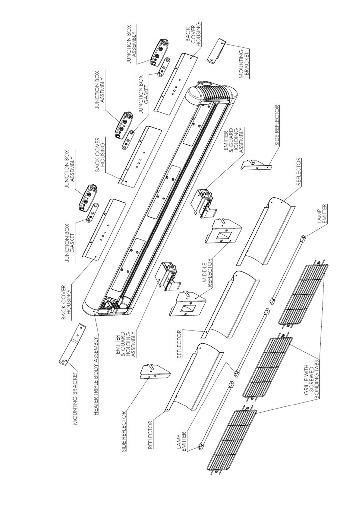
AL P H A H 3 - C O M P O N E N T PAR T D I AG R AM
Fig. I
12 of 16 Ref No. 043484-EN-S Iss. A
Disconnect from the mains ower before any attem ts are made to re lace the lam
emitter. Contact your distributor for the correct re lacement quoting model ty e and
rating from the rating label. We recommend you read through the rocedure and refer
to the arts diagram on the revious age of this manual before commencing work.
1. Ensure the heater and lamp emitter is cool and the power supply is disconnected to all
lamp emitters before disassembly.
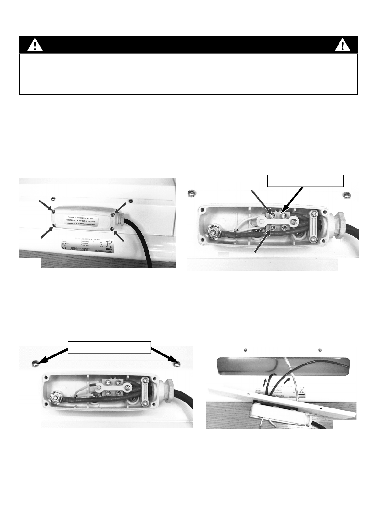
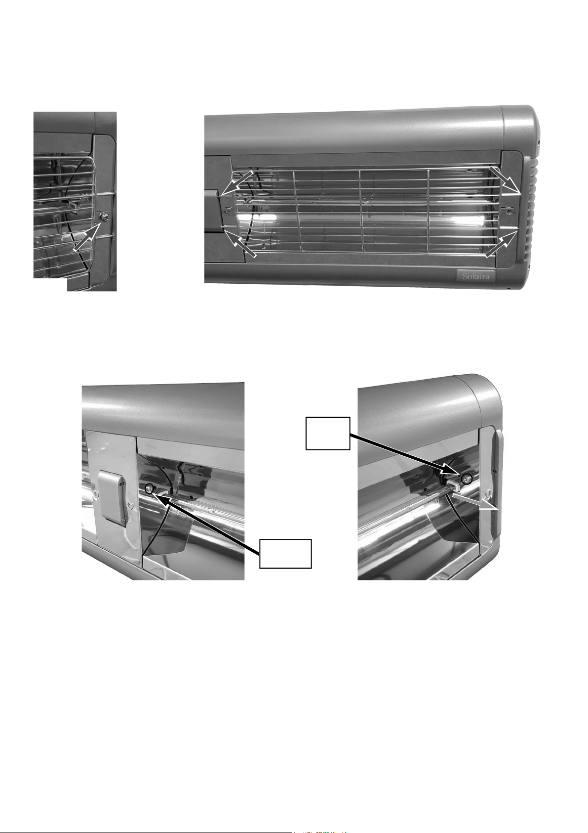
2. Remove the screws from the junction box at the back of the lamp emitter to be replaced
and lift off the lid - see Fig. J.
Fig. J
C AU T I O N
R E P L AC I N G A L AM P E M I T T E R
3.
Disconnect the lamp emitter from the connector block by unscrewing the screws
highlighted above in Fig. K and remove the lamp emitter wires from the connector block.
4. At the back of the heater, remove the plate holding the junction box behind your lamp
emitter by removing the two fixing screws as shown in Fig. L.
5. Pull the lamp emitter wires one at a time through the gasket on the terminal plate to
remove as shown in Fig. M.
Fig. L Fig. M
continue on next page...
Fig. K
CONNECTOR BLOCK
FIXING SCREWS
13 of 16 Ref No. 043484-EN-S Iss. A
continue on next page...
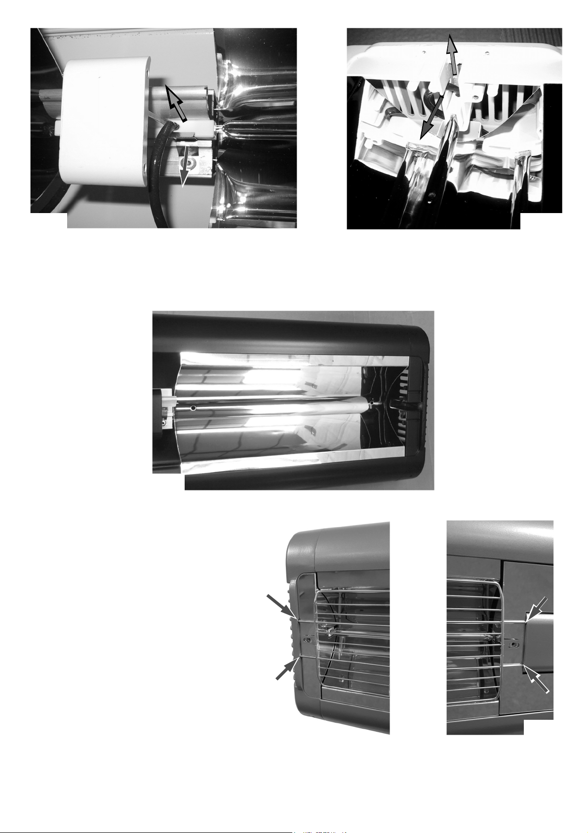
7. Remove the screws from the middle reflector on both sides (Fig. P) and the single screw
from the side reflector (Fig. Q). Lift them up and away from the heater to reveal the ceramic
caps on the lamp emitters.
Fig. QFig. P
POINTED
SCREW
8. Release the lamp emitter end by pressing the top edge of the spring clip away from the
lamp emitters ceramic end cap. Gently lift the end of the lamp emitter upwards so it is no
longer being retained by the clip (Fig. R). The wire can then be gently pulled from behind the
reflector.
9. The lamp emitter wire at the opposite end should be pulled out of the side slot (Fig. S) and
the lamp emitter can be lifted up completely. The wire can then be gently pulled forward so
that it also comes out from behind the reflector.
6. At the front of the heater, remove the screws from the grille tabs at both sides of the grille
as shown in Fig. N (taking care to retain the spring washers) then remove the grille by
pulling it out from the centre and prizing the prongs away from their locating holes at one
end (Fig. O) and pull out of opposite end.
BLUNT
SCREW
Fig. N Fig. O
14 of 16 Ref No. 043484-EN-S Iss. A
continue on next page...
10. The lamp emitter can now be removed away from the heater leaving it ready for the new
lamp emitter to be fitted as shown in Fig. T.
Fig. T
Fig. SFig. R
11. Refit the new lamp emitter in
reverse order making sure that no
wires can get trapped. Replace the
side and middle reflectors and their
screws before any other parts are fitted
to make sure the lamp emitter is held
securely.
12. Refit the grilles by taking a grille
and inserting the 2 × prongs into the
holes in the end of the heater (left side
shown below in Fig. U) and gently flex
the wire grille to insert the 2 × opposite
prongs into the grille holder holes (to
the other side of the lamp emitter as
shown in Fig. V).
Fig. U Fig. V

15 of 16 Ref No. 043484-EN-S Iss. A
15. Check the fitment of the grille by individually gripping them and moving them to their
extreme left and right positions/pushing up and down to ensure they are all securely located
(Fig. Z).
13. When fitting the middle grille, insert the 2 × prongs into the holes in the grille holder (Fig.
W) and gently flex the grille to insert the 2 × opposite prongs into the opposite grille holder
holes as shown in Fig. X.
14. Refit the screws into the tabs on the grilles ensuring there is a spring washer under all of
the screw heads (Fig. Y).
Fig. Y
Fig. W Fig. X
Fig. Z

IMPORTANT - SAVE THESE
INSTRUCTIONS FOR FUTURE REFERENCE
Solaira Alpha H3 277V
CANADA & USA MODELS:
Solaira Alpha
H1 277V
Also available in this range...
IMPORTANT - SAVE THESE
INSTRUCTIONS FOR FUTURE REFERENCE
INFORESIGHT CONSUMER RODUCTS INC.
125 Traders Blvd. E Unit # 4, Mississauga, Ontario L4Z 2H3
Tel 905-568-7655 - Fax 905-568-7521 - Email info@solairaheaters.com - Website www.solairaheaters.com
Due to our policy of ongoing improvement, we reserve the right to make changes without notice.
© 2021 INFORESIGHT CONSUMER PRODUCTS INC.
Ref No. 043484-EN-S Issue No. A
247748
C = COLOR CODE
SALPHA -45277C (240V - 75W / 277V - 4500W)
SALPHA -45277L1C (240V - 75W / 277V - 4500W) CANDEL LOW LIGHT
SALPHA -60277C (240V - 4500W / 277V - 6000W)
SALPHA -60277L1C (240V - 4500W / 277V - 6000W) CANDEL LOW LIGHT
Solaira Alpha
H2 277V
Other Solaira Heater manuals

Solaira
Solaira ICR H3 Series User manual

Solaira
Solaira Cosy XL User manual

Solaira
Solaira SCOMH01500 Use and care manual

Solaira
Solaira SALPHA15120 User manual

Solaira
Solaira Cosy XL Double User manual

Solaira
Solaira SCOSYXLAW15120 User manual

Solaira
Solaira Malibu MAL 45240 User manual

Solaira
Solaira Cosy XL User manual

Solaira
Solaira SALPHAH3-30240 User manual

Solaira
Solaira ICR Series User manual


