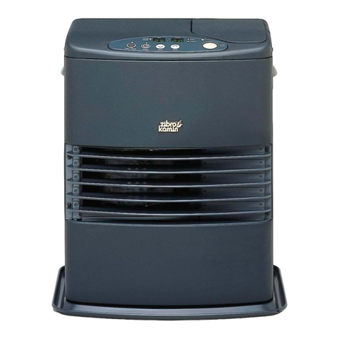
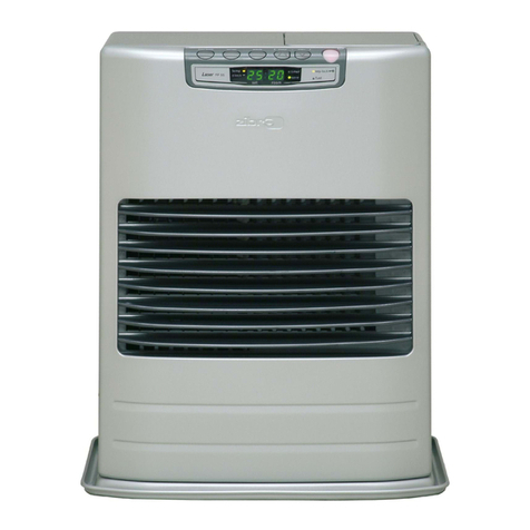
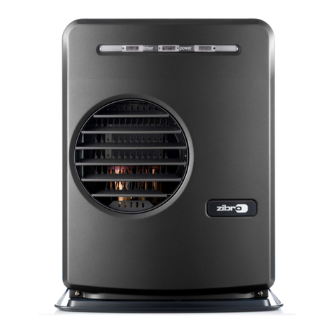
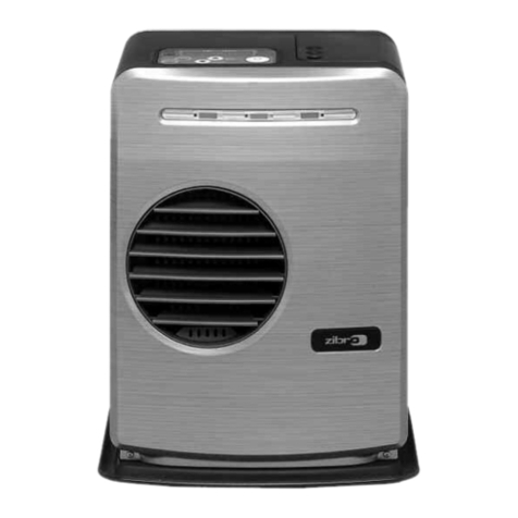
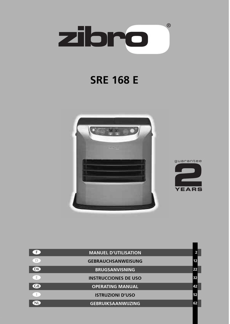
Zibro Laser 73 User manual

Laser 73
3
26
OPERATING INSTRUCTIONS
KULLANIM KILAVUZU
4
TR
co_Laser73.qxd 02-11-2006 10:46 Pagina 1

3
4OPERATING INSTRUCTIONS
Dear Sir, Madam,
Congratulations with your purchase of the Zibro, the number one brand among
movable heaters. You have purchased a first-class quality product, which will
serve you for many years to come. This, of course, provided you use the heater
correctly. Please read these Directions for Use first, to ensure maximum lifetime
for your Zibro.
Your heater comes with a 24-month manufacturer’s warranty on all defects in
material or workmanship.
Wewish you much warmth and comfort with your Zibro.
Yours sincerely,
PVG International B.V.
Customer Service Department
1READ THE DIRECTIONS FOR USE FIRST.
2IN CASE OF ANY DOUBT,CONTACT YOUR ZIBRO DEALER.
man_Laser73_uk.qxd 02-11-2006 10:44 Pagina 3

4
WHAT YOU NEED TO KNOW IN ADVANCE
THE RIGHT FUEL
Only use Class C1 paraffin fuel in accordance with BS2869: Part 2, or equivalent. Your Zibro heater has been
designed for use with high-quality water-free pure paraffin oil, such as Zibro Extra or Zibro Kristal. Only
fuels of this kind will ensure clean and proper burning. Lower quality fuel may result in:
Eincreased possibility of malfunctioning
Eincomplete burning
Ereduced heater lifetime
Esmoke and/or smells
Edeposits on the grid or mantle
Using the right fuel is therefore essential for safe, efficient, and comfortable use of your heater.
Always refer to your local Zibro dealer for the right fuel for your heater.
TIPS FOR SAFE USE
1Make sure that children are always aware of the presence of a burning heater.
2Position the front of the heater at a distance of minimum 1.5 metres from walls, curtains, and furniture.
3Do not use the heater in dusty rooms. You will not have optimum burning in such rooms. Do not use the
heater in the immediate surrounding of a bath, a shower or a swimming pool.
4Switch off the heater, before you leave or go sleeping. Unplug the heater as well, when you go away for
alonger period of time (e.g. holidays).
5Store and move fuel only in suitable tanks and jerrycans.
6Make sure that the fuel is not exposed to heat or extreme temperature changes. Always store the fuel in
acool, dry and dark place (sunlight will affect the quality).
7Never use the heater in places where harmful gasses or fumes may be present (e.g. exhaust gasses or
paint fumes).
8Bewarethat the grid of the heater becomes hot. If the appliance is covered there is a risk of fire.
• The first time you ignite your heater it will smell like ’new’ for a short time.
• Store your fuel in a cool and dark place.
•Fuel has a limited shelf life. Start every heating season with renewed fuel.
• The right quality of fuel will be assured, when you use ZibroExtra or ZibroKristal for
your heater.
• If you change to another brand and/or type of parrafin oil, you must first finish up all
the remaining fuel in the heater.
man_Laser73_uk.qxd 02-11-2006 10:44 Pagina 4

1. Introduction
This chapter contains all the relevant information,
specifically:
• Installation specifications
• List of installation tools
• Basic requirements for the installation of the fuel
tank
•Instructions for the installation of the Laser System
The heater can be installed at any location, on condi-
tion that thereis full compliance with electrical, fuel
and emission regulations.
Before you start installing the heating system (inclu-
ding electrical wiring and fuel supply equipment),
check the local building and fire safety regulations. The
requirements stipulated in these regulations must be
respected in order to guarantee a legally approved
installation and correct operation.
The heater was designed to be used to a
maximum altitude of 1000m above sea level.
Contact your dealer for the necessary
adjustments if you wish to use it at a higher
altitude.
2. Moving the heater
In addition to the space required for the heater,extra
room must be kept free for air circulation. The Laser
System can be placed on any type of flooring and oper-
ate safely, unless fuel or fire safety regulations specify
otherwise. Check the gaps in the manner stipulated in
the instructions in the manual.
Recommended tool kit
1. Crosshead screwdriver
2. Steel tape measure
3. Felt-tip pen or pencil
4. Cement for exterior use
5. Electric drill (clockwise and anti-clockwise
recommended)
6. Hole cutting saw, jig saw or other tools suitable for
sawing a hole of 70~80 mm for the exhaust pipe
7. Long drill
8. Standard screwdrivers
9. Adjustable spanners (various sizes)
10.Copper tube cutter
11.Reamer
12.Volt, Ohmmeter
13.Spirit level
14.Plumber’s tape for tube screw thread
15.Small range of self-tapping screws
16.Range of pliers (pin tongs, needle nose pliers,
cutting pliers, locking pliers)
17.Insulated screwdriver
18.Protective material for your floor
19.Container for fuel exhaust pipe
3. The electrical supply system
The electrical system must be protected from overloads
by an at least 5-Ampere fuse or contact breaker.
Some installations (such as for use in mobile
homes) must be fitted with a permanent
connection to the household power circuits.
This must be done by a recognised
electrician.
4. Fuel tank
Heater fuel (exclusively water-free, pure paraffin oil) in
200/1000 litrestorage tanks located outside. If large
tanks are used, a pressure regulator with a max. of 2.5
PSI (± 0.17 bar) must be fitted at the inlet on the
heater. This must be carried out in strict adherence to
all local standards and/or building regulations.
Chapter 1, INSTALLATION
5
☞
☞
man_Laser73_uk.qxd 02-11-2006 10:44 Pagina 5

5. Wiring for the room temperature sensor
Atemperature sensor that can be fitted to a wall mea-
sures the room temperature in order to automatically
regulate the heating. The standard sensor wire is
approximately 2.5 m long.
The sensor may not be placed in a draught,
direct sunlight or the warm air flowing out
of the heater.This may cause incorrect
temperature indications.
6. Unpacking
Save all packaging materials for possible future trans-
portation.
A) Remove the cardboard (drilling) template and the
user’s manual from the packaging.
B) Remove the base plate and the box with the
installation kit from the packaging.
C) Remove the heater from the packaging.
D) Remove the plastic bag covering the heater.
E) Remove the plastic bag containing the parts.
F) Remove the exhaust pipe from the bottom of the
box.
G) Check that all parts are present.
Only the standard feed and exhaust system
is supplied with the heater.
Chapter 1, INSTALLATION
6
Fig. 1-1: Gaps heater/exhaust pipe
Laser 73
More than 60 cm
More than 30 cm
More than 1,5 m
More than 30 cm
Morethan 10 cm
☞
☞
man_Laser73_uk.qxd 02-11-2006 10:44 Pagina 6

Chapter 1, INSTALLATION
7
Fig. 1-2 Gaps heater/exhaust pipe
Fig. 1-1 (continued) gaps heater/exhaust pipe
Flammable object
Not less than 60 cm
Flammable object
Non-flamma-
ble object
45°C
Not less than 30 cm
Exhaust pipe
Not less than 60 cm
Not less than 20 cm*
Not less
than 45 cm
Not less
than 45 cm
Frontal obstruction
45 cm or more
20 cm or more
Snow-covered surface or ground
Important: The gap with the ground must be enlarged in areas
subject to heavy snowfall. Important:Awindbreaker may be necessary in open areas that
aresubjected to strong winds.
Extension tube of
max. 3.0 metres
(with max. 3 bends) Must be higher
Snow
Strong wind
Distance from
exhaust pipe to
windbreaker mini-
mum 45 cm
Not less
than
45 cm Windbreaker
Not less than 20 cm*
*This clearance has to be present also in case of snowfall, etc.
man_Laser73_uk.qxd 02-11-2006 10:44 Pagina 7

☞
After using the installation template as a guide for the
drilling of the hole for the exhaust pipe, the Laser can
be installed normally, according to the procedure in the
illustration.
If the template is lost or the heater has to be moved,
these are the dimensions and locations of the holes for
the fuel pipe and exhaust pipe.
Do not remove any components from the
heater. Always contact your dealer if repairs
arerequired.
If the electricity cable is damaged, this may
only be replaced with type H05 VV-F and by
arecognised installer.
Chapter 1, INSTALLATION
8
Laser 73
Fig. 1-3 Template
Back of the heater
Fuel inlet
The center of
the flue pipe
Floor
Fuel inlet
12 3/8”
(310 mm)
12 3/8”
(310 mm)
35/8”
(92 mm)
35/8”
(92 mm)
17/8”(92 mm)
12 3/8”
(310 mm)
12 1/2”
(317 mm)
man_Laser73_uk.qxd 02-11-2006 10:44 Pagina 8

Chapter 1, INSTALLATION
9
Standard installation parts
The following list of standard installation parts is sup-
plied with your heater. It may be necessary to order
extra parts from your Zibro dealer if other installation
methods are required.
Base plate (1) Wall hooks (2 set)
Pipe holder (1) Pipe lock (1)
Exhaust pipe (1) Right-angled exhaust pipe bend (1)
(3) (3)
man_Laser73_uk.qxd 02-11-2006 10:44 Pagina 9

Chapter 1, INSTALLATION
10
Discharge chute (1) Right-angled air hose (2)
Flexible air hose (1) Hose clip (2)
man_Laser73_uk.qxd 02-11-2006 10:44 Pagina 10

Chapter 1, INSTALLATION
11
1. For the standard installation, use the template sup-
plied to position the hole for the exhaust pipe correct-
ly. Use cellotape or small nails to attach the template to
the desired position on the wall (see Fig. 4).
Fig. 4
Comment: The heater must be installed on a strong
and stable floor. The floor must be flat and level. If this
is not the case, the heater can be levelled by means of
adjustable legs. This can be checked with the plumb
line.
2. Drill the hole for the exhaust pipe. Use a hole saw
with a diameter of 70~80 mm (see Fig. 5). The opening
on the interior side of the wall must be a little higher
than the opening on the outside in order to create a
slight gradient in the feed-through and exhaust pipe
after installation (approximately 2º) (see Fig. 6). This
ensures that condensed water in the exhaust pipe flows
to the outside and prevents the penetration of rainwa-
ter and snow after installation.
Fig. 5 Fig. 6
2°
Tape
man_Laser73_uk.qxd 02-11-2006 10:44 Pagina 11

Chapter 1, INSTALLATION
12
Inner fiue pipe
Wood screws
Arrow
inside Outsida
230~320mm
2˚ downward Min.
Fig. 7
Outer flue pipe
Exhaust joint
Intake joint
Fig. 8
3. Install the inner flue pipe.
a. For wall thickness 230~320mm.
From inside the room, insert the inner flue pipe through the hole. Make sure the arrow on the inner flue
pipe is pointing up. Secure the inner flue pipe to the wall with the three wood screws. (See Fig. 7)
b. For wall thickness 130~230mm.
Remove Intake joint and Exhaust joint from Outer flue pipe (See Fig. 8).
Outside
Inside
man_Laser73_uk.qxd 02-11-2006 10:44 Pagina 12

Chapter 1, INSTALLATION
13
Fig. 9
Fig. 10
Inner flue pipe
Inside Outside
Arrow
Outer flue pipe frange
Outer flue pipe
A
Outer flue pipe frange
2˚ downward Min.
4. Attach the right-angled exhaust pipe bend to the
outlet of the exhaust pipe. Cut, if necessary, the flexible
air hose to size. Fasten the right-angled air hose to
both ends of the flexible air hose – now attach the
right-angled air hose to the inlet of the exhaust pipe.
Attach the right-angled air hose to both ends of the
flexible air hose. Now fasten the right-angled air hose
to the inlet of the exhaust pipe.
Fasten the right-angled air hose onto the inlet with a
hose clip. Seal the inlets and outlets that arenot being
used with the caps supplied. Check that the caps are
firmly in position (See Fig.10). Use water or soap suds
to provide lubrication when fitting the right-angled air
hose onto the flexible air hose. The total length of the
exhaust pipe may be a maximum of 3 m (max. 3 bends).
Hose clip
Cap
Outlet
Right-angled exhaust bend
Right-angled air hose
Flexible air hose
c. From outside, insert the outer flue pipe through the hole. Secure the outer flue pipe to the wall by turning
it clockwise. This locks the two halves together (See Fig. 9).
IMPORTANT: Make sure the arrow on the outer flue pipe frange is pointing up.
Make sure to secure the outer flue pipe well. (A-part shown in Fig. 9)
man_Laser73_uk.qxd 02-11-2006 10:44 Pagina 13

Chapter 1, INSTALLATION
14
6. Fasten the right-angled air hose to the inlet with the
hose clip. Attach the right-angled exhaust bend to the
exhaust pipe with the pipe holder (attach the pipe
holder to the connection of the right-angled exhaust
bend). Attach the right-angled exhaust bend to the
outlet by sliding the pipe lock into the outlet clip (See
Fig. 12).
Fig. 12
Pipe holder
Pipe lock
7. Installation of an external fuel tank
The installation of an external fuel tank is illustrated in
adiagram (Fig. 1-11). The fact that installation tech-
niques for fuel tanks vary means that it is impossible to
provide a specific installation procedure. However, cer-
tain criteria determine the manner in which the heater
is supplied with fuel. Use the following checklist as a
guideline for the installation of an external tank.
5. Place the heater in the desired location. Attach the
right-angled exhaust bend to the outlet (the top open-
ing) and attach the right-angled air hose to the inlet.
Check that everything is firmly attached (See Fig. 11).
Fig. 11
Outlet
Inlet
Right-angled exhaust bend
Right-angled air hose
man_Laser73_uk.qxd 02-11-2006 10:44 Pagina 14

☞
Chapter 1, INSTALLATION
15
Fig. 15
8. Make sure the position of the heater is level by using
the plumb bob located at the right side of the heater.
The plumb bob weight should be within the circle. If
the plumb bob weight is not within the circle, adjust
the heater legs until the plumb bob weight is within
the red circle (See Fig. 13 & 14).
Good
Bad
Plumb bob as viewed from above
Circle
Weight
9. A room temperature sensor is provided with a 2.5 m
long extension wire. It is located on the rear of the cabi-
net. Make sure that the extension wire is not touching
the exhaust pipe. The room temperature sensor can be
installed either with the self adhesive tape on the back
or with a wood screw provided with the sensor depend-
ing on the type of surface chosen for installation.
NOTE: Choose a location for the sensor that is
not in the path of direct sunlight, drafts or the
flow of warmair from the heater.
(a) Self Adhesive Tape
Peel offthe protective tape on the back of the sen-
sor and expose the adhesives. Place the sensor on
the desired location on the wall and press down.
(b) Wood Screw
Screw down the wood screw provided with the
heater into the desired location on the wall. Hook
the back of the room temperature sensor.
10. After installation is completed, secure heater to the
wall with the wall brackets provided with the heater.
Make sure the heater is parallel to the wall (See Fig.
15).
Fig. 13Fig. 13 Fig. 14
(a) (b)
11. Before ignition, recheck the following:
a. All connections aretight and firm.
b. The heater and the flue pipe areas are free of any
materials.
c. The heater is level and parallel to the wall.
man_Laser73_uk.qxd 02-11-2006 10:44 Pagina 15

Chapter 1, INSTALLATION
16
☞
CHECKLIST
• Check whether the heater has been connected to a
suitable socket.
• Check that a suitable quantity of petroleum is in the
fuel tank.
• Ensure that the fuel is free of water or other
contaminants.
• Check that the fuel tank is in good working order –
it must be free of rust, corrosion and/or leaks.
• Inspect the fuel pipe for signs of leaks, loose
connections, cracks, air bubbles or blockages.
•Check that the fuel valves on the fuel tank and the
fire safety valve are open in order to allow the free
flow of fuel.
• Check outside the building in order to ascertain that
there is no fuel or obstructions to the free
circulation of air in the area immediately adjacent
to the exhaust pipe.
• Inspect the inlet air hose for cracks, loose
connections or blockages.
• Check the outlet air hose for cracks, loose
connections or blockages.
• Check the back of the heater to ensure that the
airflow to the air circulation ventilator is not
obstructed.
• Inspect the interior of the building to ensure that
the area immediately adjacent to the heater is free
of fuel and objects that may obstruct the free flow
of air.
• Check that the room sensor is not exposed to
draughts, direct sunlight or heat radiated directly
from the heater.
• Use a spirit level to check that the heater is level.
If this inspection brings any faults to light, resolve these
problems beforeusing the heater.
Use only water-free high quality pure
paraffin oil. Never use gasoline, LPG,
camping gas or other flammable liquids.
The use of these substances may cause
explosions or fire.
Available fuel supply options
The fuel supply of the Laser 73 can be set up as follows:
Large gravity-operated exterior tank
To install a large gravity-operated exterior tank, follow
the instructions below. We recommend that you call in
arecognised installer.
The inlet pressure to the heater may not exceed 2.5 psi.
Use a pressure reduction valve with a maximum thrust
of 2.5 psi ( ± 0.17 bar).
The installation height of the bottom of the fuel tank
must be 40 cm or more above the level of the floor on
which the heater is standing. This will ensure that there
is sufficient fuel inlet pressure. The distance between
the floor surface on which the heater is standing and
the top of the fuel tank may not exceed 2.5 metres.
This will prevent excessive fuel inlet pressures.
The pipe may not have any inverted U-bends (to pre-
vent air pockets that may block the fuel supply).
We recommend using a water-blocking filter in the fuel
pipe leading into the tank. A cut-offvalve must be fit-
ted to the tank.
We recommend installing a fire safety valve and a fuel
filter in the fuel pipe.
The use of a cut-off valve, placed just before the pipe
enters the building, will limit the quantity of fuel to be
tapped off to a minimum if the heater requires mainte-
nance.
man_Laser73_uk.qxd 02-11-2006 10:44 Pagina 16

Chapter 1, INSTALLATION
17
If a fuel pipe inside the building is more than 90 cm
long, you must use an extra cut-off valve.
The external fuel tank must be placed at least 2 metres
away from any heat source.
The external fuel tank must have a filling opening on
the top and a ventilation opening with a weather-
resistant cap on the side. Some tanks use the same
opening for ventilation and filling.
Important: Ensurethat the fuel pipe is free of dust and
waste particles. These particles may cause problems in
the fuel receptacle.
Copper tubing with an exterior diameter of 3/8” must
be used for the fuel pipe.
The external tank and the installation of the external
tank must meet fire applicable (local) regulations. Refer
to the local authorities for these regulations.
Installation may be done by a qualified person only.
Fig.1-11 Connection to the fuel pipe
Laser 73
Fire safety valve
(recommended)
Fuel drainage
container with
unlocking button
Valve (recommended)
2.5 m (max.)
40 cm (min.)
Fuel tank placed
outside
Fuel filter: Preferred type
–water intake cut-off
valve
Valve
Loop
Copper tube with
3/8 exterior
diameter
man_Laser73_uk.qxd 02-11-2006 10:44 Pagina 17

1. Introduction
The Laser 73 is an easy to use vented petroleum heater.
It provides considerable quantities of heat, automati-
cally regulates the room temperature, uses very little
fuel and electricity and has options for automatic or
manual operation.
This chapter provides all the information required for
the operation of the Laser heater system. All specified
operating procedures must be carried out in the order
in which they are described.
2. Laser 73 heater specifications
• Nominal yield
(as applied to petroleum heaters): 92%
• Power consumption:
• Fuel source: external tank
•Room volume indication when used as main heating
source: 130 - 440m3
18
Chapter 2, OPERATION
Low Medium High
Heat yield (W) 3650 7300 10350
Fuel consumption (l/h) 0.38 0.76 1.08
Ignition Burning
280 W 80 W
man_Laser73_uk.qxd 02-11-2006 10:44 Pagina 18

3. Operating elements and lights
1. ON/OFF button:
The main switch to turn the heater on and off.
Switch it “ON” to activate the heater. Combustion
will start after a 3-9 minutes pre-heating period.
The heater has 4 settings “HIGH”, “MEDIUM”,
“LOW” and “OFF”.
2. Button to activate/deactivate programmed timer.
The switch activates and deactivates the automatic
operation setting as programmed in the timer.
3. Temperatureadjustment button
“NORMAL” and “SET-BACK” temperature selection
switches offer the user the option to select the
desired temperature during manual or automatic
operation. Adjustment is extremely simple.
4. Buttons to adjust the clock and the timer
Timer and clock settings can be adjusted by pressing
the hour and minute buttons.
5. Time selector switch
When the timer and the clock have been
programmed and you wish to see a time indication,
returnthe selector switch to the ‘normal’ position.
The start and finish times of “SET-BACK” (timer) are
also set with this switch.
6. Information display
Displays the clock, set temperature, room
temperature and error codes.
7. Operating mode lights
-indicate whether the heater is operating at the
“HIGH”, “MEDIUM” or “LOW” setting.
-Indicate when the heater is operating and flash
when the heater is in the cleaning mode.
- Switch on during automatic operation.
- Switch on when the heater is operated manually
or in “NORMAL” automatic operation.
-Switch on when the heater is “SET-BACK” setting
of automatic operation.
19
Chapter 2, OPERATION
Fig. 2-1 Operation panel
2. Button to activate/deactivate pro-
grammed timer (auto-switch)
3. Temperature adjustment button
5. Timer selector switch
4. Buttons to adjust the
clock and the timer
6. Information display
7. Operating mode lights
1. ON/OFF button
man_Laser73_uk.qxd 02-11-2006 10:44 Pagina 19

4. Prior to use
Step 1: Open the valve(s)
Screw the valve on the top of the removable tank open
or open the valve for the external fuel tank and the
fire safety valve of the heater (if present).
Step 2: Start the fuel supply
Carefully press the red unlocking button for one sec-
ond to release the float in the fuel receptacle.
The fuel receptacle only has to be unlocked when the
heater is activated for the first time or after it has run
out of fuel, or if the heater has not been used for an
extended period of time. Unlocking may also be
required if the fuel inlet pressure exceeds 2.5 psi
(± 0.17 bar). In this case, a pressure reduction valve
must be installed.
Step 3: Adjust the clock
Important: The clock on the heater must always be set
to the correct time.
A. Switch the time selector switch to “CLOCK SET”
B. Press the “HOUR” and the “MINUTE” buttons to
adjust the hours and minutes. Pressing the “HOUR”
or “MINUTE” button once will adjust the time by
one unit (hours or minutes respectively). Holding
the button down accelerates the adjustment of the
time display.
All clock and timer settings are deleted if the power is
cut off for a period longer than 10 seconds. The infor-
mation display flashes “PM 12:00” when the heater is
switched off. The clock and timer now have to be
reprogrammed.
C. Set the timer switch to the “NORMAL” setting after
completing the clock adjustment. The current time
is then displayed on the digital indicator.
5. Manual operation
The heater is operated directly by the user. However,
the heat yield is controlled automatically in accordance
with the room temperature registered by the tempera-
turesensor.
Step 1: Select manual operation
If the heater is in “AUTO” mode, switch the “AUTO”
switch to “OFF” to change to “MANUAL” operation.
Step 2: Switch the heater ON
Press the ON/OFF button until “ON” is displayed. The
current room temperature and the set temperature are
displayed on the information display.
The ON/OFF light starts to flash, after which the heater
will switch on. The heater will not work if the room
temperatureis higher than the desired temperature
setting.
Note: (*) The start-up time depends on the room tem-
perature.
After 9-15 minutes, the heater will automatically select
the correct operating mode and the ON/OFF button
will now be illuminated continuously.
Room temperature:
under 0°C -15 minutes
0°C - 15°C - 12 minutes
15°C - 9 minutes
If no flames are visible after the start-up period, the
heater will deactivate and then restart automatically. If
flames are still not detected, the heater will deactivate
and will have to be restarted manually (error code EE-2
on information display).
Step 3: Setting the room temperature
Slide the “NORMAL” temperature selector to the
selected position in order to set the desired room tem-
perature.
The desired temperature setting is shown in the infor-
mation display when you set the room temperature.
The scale on the temperatureselector only serves as a
reference point. The figures on the information display
and on the scale may differ,this is normal.
The operating mode is automatically controlled in
accordance with the room temperature detected by the
room temperature sensor. The heater works in the
“HIGH” operating mode until the room temperature
has reached the desired level.
When the room temperature reaches the chosen set-
ting, the heater automatically switches to the “MED”
or “LOW” operating mode in order to maintain the
desired temperature. If the room temperature exceeds
20
Chapter 2, OPERATION
man_Laser73_uk.qxd 02-11-2006 10:44 Pagina 20

the setting by approximately 2°C, the heater is
switched off automatically. If the room temperature
drops, the heater will automatically restart in order to
maintain the desired temperature.
Note: The operating mode lights indicate the mode in
which the heater is working at any one time. The
heater switches automatically between the “HIGH”,
“MED” and “LOW” operating modes in order to main-
tain the desired temperature.
6. Automatic operation
Automatic operation is initiated by programming the
time/temperature settings for a specific time. Working
in “SET-BACK” mode is programmed for a 24-hour peri-
od. This mode was developed to save energy by using a
lower temperature setting, usually at night.
Programming is carried out as follows (night setting):
Ensure that the clock has already been programmed
(see step 4, chapter 2-5).
Step 1: Set the start time of the “SET-BACK” mode
A. Slide the time selector switch to the “START SET-
BACK” position.
B. Press “HOUR” and “MINUTE” to set the desired start
and finish times. (pay attention to the AM or PM
designation).
When setting the “SET-BACK” time, the “MINUTE”
button will change in increments of 10 minutes
(e.g. 10:00, 10:10, 10:20 etc.).
C. The start time of the “SET-BACK” mode is then
shown in the information display (e.g. PM 10:00).
Step 2: Set the finish time of the “SET-BACK” mode.
While the time selector switch is in the “END SET-
BACK” mode, you must now programme the finish
time in the same manner as described above
(e.g. AM 6:00).
After programming, move the time selector switch
back to the NORMAL position.
Step 3: Set the room temperature
Slide the “SET-BACK” temperature selector (night
temperature) to the desired position (e.g. 15°C).
Turn the AUTO switch to the “ON” position.
Step 4: Set the ON/OFF switch to ON
If the temperature is lower than or drops below the
requested temperature, the heater will start automati-
cally.
7. Reprogramming the heater
In certain circumstances (e.g. power cuts), it may be
necessaryto reprogram the heater. Follow the steps
specified above when reprogramming the timer. Do
not forget to set the clock (step 4, chapter 2-5).
8. Cleaning system for the ignition rod
Automatic cleaning system of the ignition rod
The heater will switch off automatically each day at
2:00 in the morning, allowing the ignition rod to clean
itself for 10 minutes. CL: 10 will then appear in the dis-
play,changing everyminute to CL:09, CL: 08, etc.
21
Chapter 2, OPERATION
Fig. 2-2
Approximately 2°C
Approximately 0.7°
Set temperature
High Medium Low Off
Re-ignition
PM 10:00
(22:00) PM 10:00
(22:00)
AM 6:00
(06:00)
1Start set-back 2Finish set-back
12
Fig. 2-3
15°C
(60°F)
20°C (75°F)
15°C
(60°F)
man_Laser73_uk.qxd 02-11-2006 10:44 Pagina 21
Table of contents
Languages:
Other Zibro Heater manuals

Zibro
Zibro R 617 E User manual

Zibro
Zibro SRE 260 User manual

Zibro
Zibro Kamin SRE 156 User manual

Zibro
Zibro Kamin R 27 C User manual

Zibro
Zibro Kamin R 50 C User manual

Zibro
Zibro R 617 E User manual

Zibro
Zibro SRE 25 TC User manual

Zibro
Zibro SRE 25 E User manual

Zibro
Zibro Kamin R 102 C User manual

Zibro
Zibro Kamin R 50 C User manual

Zibro
Zibro R 59 C User manual

Zibro
Zibro Laser FF 55 User manual

Zibro
Zibro R 170 C User manual

Zibro
Zibro SRE 230 E User manual

Zibro
Zibro R 316 C User manual

Zibro
Zibro SRE 250 User manual

Zibro
Zibro R 56 C User manual

Zibro
Zibro SRE 228 TC Silver User manual
Zibro
Zibro SRE 229 E User manual

Zibro
Zibro SRE 178 E User manual