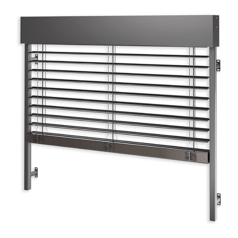
SolarGaps SGV1C80-6-W Series User manual

VENETIAN BLINDS WITH SOLAR PANELS
OPERATION MANUAL
EN

EN.2
Dear Customer!
SolarGaps would like to express its gratitude for your choice!
Our experts use best working practices and modern technologies to
ensure efficient utilisation of solar energy as you use our product.
We provide quality control at every production stage: from design of
engineering drawings and incoming control of materials and components to
outgoing control of finished products and packing of goods for further
transportation — with all operations performed by highly qualified personnel.
We strongly recommend you to read this manual carefully before installing
and using the product.
YOU CAN RELY ON THE TOP QUALITY OF SOLARGAPS PRODUCTS!

EN.3
CONTENTS
!
1.!
Functionality!and!field!of!application!...............................................................................................!EN.!4!
2.!
Reference!to!standards!................................................................................................................!EN.!5!
3.!
Technical!specifications!and!product!range!.................................................................................!EN.!6!
4.!
Delivery!set!...................................................................................................................................!EN.!8!
5.!
Product!description!and!operating!principle!...............................................................................!EN.!9!
6.!
Preconditions!for!installation!.....................................................................................................!EN.!11!
7.!
Product!installation!.....................................................................................................................!EN.!16!
8.!
Start-up!and!adjustment!works!..................................................................................................!EN.!22!
9.!
Product!testing!...........................................................................................................................!EN.!23!
10.!
Mobile!Application!instructions!...............................................................................................!EN.!24!
11.!
Transportation!rules!.................................................................................................................!EN.!37!
12.!
Storage!rules!.............................................................................................................................!EN.!38!
13.!
Safety!instructions!....................................................................................................................!EN.!39!
14.!
Fire!safety!instructions!.............................................................................................................!EN.!40!
15.!
Operation!conditions!and!useful!life!........................................................................................!EN.!41!
16.
!Maintenance!.............................................................................................................................!EN.!42!
17.!
Troubleshooting!.......................................................................................................................!EN.!43!
18.!
Warranty!obligations!................................................................................................................!EN.!44!
19.
!Disposal……………………………………………………………………………………………………………………………….EN.47!
Annexes:!!
!
1.
Warranty!Certificate.............................................................................................................!
EN.48!
2.
Declaration!of!Conformity....................................................................................................!
EN.49!
3.
Declaration!of!Performance.................................................................................................!
EN.50!

EN.4
1. Functionality and field of application
The SolarGaps solar panel blinds system (hereafter referred to as the BLINDS) is a smart
blinds system using built-in photovoltaic elements, which generate the electrical power. You
can use this electricity to power your home appliances, store it in batteries and/or sell the
excess amount to your energy supplier. SolarGaps blinds can automatically track the sun all
day long, adjusting their position to ensure optimum tilt angles for capture of solar rays and
maximum solar energy generation to provide power supply to various devices in your house,
apartment or office. SolarGaps blinds are mounted above window opening (outside of
apartment, house or office premises) and are capable to generate up to 100 W⋅h of energy
per 1 m2of the window area, which is generally enough to power 30 LED-lamps or three
MacBook laptops.
WARNING! Carefully study this Manual before starting installation (mounting) and
operation of the product.
Installation, maintenance and repairs of the product shall be performed only by
entities and organizations authorised (licensed) to perform such works or technicians
holding an appropriate certificate.
PROHIBITED! It is prohibited to carry out any works related to service and/or
repairs of the product without its prior disconnection from the power grid.
As a result of ongoing activities on improvement of the product by SolarGaps, this
document may not cover certain modifications in the design, though any such
modification shall by no means deteriorate neither technical specifications, nor design
and operational safety of the product.

EN.5
2. Reference to standards
EN 13561:2015 External blinds — Performance requirements including safety.
EN 13659:2015Shutters and external Venetian blinds. Performance requirements
including safety.
EN 60335-1:2012 Household and similar electrical appliances — Safety — Part 1: General
requirements.
EN 60335-2-97:2006 Household and similar electrical appliances — Safety — Part 2-97:
Particular requirements for drives for rolling shutters, awnings, blinds and similar
equipment.
EN 61000-3-2:2014 Electromagnetic compatibility (EMC) — Part 3-2: Limits — Limits for
harmonic current emissions (equipment input current ≤16 A per phase).
EN 61000-3-3:2013 Electromagnetic compatibility (EMC) — Part 3-3: Limits — Limitation
of voltage changes, voltage fluctuations and flicker in public low-voltage supply systems,
for equipment with rated current <= 16 A per phase and not subject to conditional
connection.
EN 55014-1:2006 Electromagnetic compatibility — Requirements for household
appliances, electric tools and similar apparatus — Part 1: Emission.
EN 55014-2:1997 Electromagnetic compatibility — Requirements for household
appliances, electric tools and similar apparatus — Part 2: Immunity.

EN.6
3. Technical specifications and product range
3.1. The BLINDS were designed and are manufactured according to the requirements of
EN 13561. The main technical specifications are presented in Table 1.
Table 1
Parameter
Value
Electrical energy generation:
- voltage, V
- frequency, Hz
- specific capacity, W/m2, minimum
- efficiency factor (EF), %, minimum
~ 230 and 110 ± 10%
50 or 60 ± 1
70
19
Adjustment of slat angle:
- slat angle adjustment range, degrees
- special software application for smartphone
70 to -30
SolarGaps
Power network:
- voltage, V
- frequency, Hz
- rated power consumption, W
207-244 and 110
50 or 60 ± 1
90 to 300
Operation conditions:
- working temperature, °C
- climate version, placement category 1
- shock resistance
-20 to +65
Moderately cold climate
group M3
Reliability indexes
- Mean time between failures, hours, min.
- total average useful life, years, min
20 000
10
Average specific weight, kg/m2
10±1
Notes:
Depends on the solar radiation intensity.
Power consumption during operation of the electric drive for adjustment of slats
position. It depends on power of the installed motor, which is determined by operational
load according to dimensions of the ordered product (length and number of salts).

EN.7
3.2. Product range of the BLINDS:
SGV1C80-6-W-(WxH)(color)(QM); SGV1C80-10-W-(WxH)(color)(QM);
SGV1C80-20-W-(WxH)(color)(QM); SGV1C80-6-R-(WxH)(color)(QM);
SGV1C80-10-R-(WxH)(color)(QM); SGV1C80-20-R-(WxH)(color)(QM);

EN.8
4. Delivery set
- SolarGaps BLINDS with solar panels .................................................................................1 set
- operation documents (Manual) ............................................................................................1 pcs.
- packing ...................................................................................................................................................1 pcs.

EN.9
5. Product description and operating principle
5.1. Product description
1– casing containing electric
drive motor, mechanisms
and control unit installed
under cornice;
2- mushroom-shaped
brackets;
3- slotted side guides;
4– slats with solar cells and
guiding rollers;
5- ladder cords (2 pcs.) — to
adjust the tilt angle of slats
with solar cells;
6- straps (2 pcs.) passing
through holes in slats with
solar panels to move the
entire blinds web up and
down;
7- bottom rail — to fix
cords and straps.
1
2
2
2
2
3
3
4
5
6
5
6
5
5
7
4
Figure 5.1. Product appearance
Figure 5.2. Arrangement of elements under the casing
5.2. Main elements of the BLINDS
5.2.1. Slats carrying attached solar panels that
convert solar energy into direct current electric
power. The number and length of slats depend on
the dimensions of ordered BLINDS.
Figure 5.3. Slats
5.2.2. Mechanism for moving slats with solar
panels up and down and adjusting the tilt
angle. The mechanism is mounted in the
cornice under the casing. It consists of electric
drive (motor), shaft and supports (number of
supports depends on the salt length, min. 2
pcs.)
Figure 5.4. Electric motor

EN.10
5.2.3. Slotted side guides (2 pcs.) ensure free
motion of slats with solar panels during operation
Figure 5.5. Slotted side guides
5.2.4. The electronic module installed in the casing
receives commands transmitted by a smartphone
via official application to control electric motor of
the BLINDS, controls output voltage of solar
panels and is connected to power consumption
and accumulation circuit for appliances, which use
the generated power.
Figure 5.6. Electronic module
5.2.5. The inverter converts generated power from DC to AC (~ 230 V 50 Hz) or
(~ 110 V 60 Hz) used as power supply for the majority of home appliances. Besides, if
needed, it allows connecting these consumers to the external power grid, or vice versa –
supplying the excess generated energy to the grid, which gives the right to respective
compensation according to the law. The connection cable for the inverter is attached
through cable duct QM.
5.2.6. The battery, which can be incorporated into the BLINDS system, allows optimizing
power supply of the house through redistribution of accumulated and consumed
electrical energy.
The BLINDS are controlled via Wi-Fi by using special mobile application and automatically
adjust the tilt angle of slats with solar panels, while tracking the sun position to ensure the
maximum power generation.

EN.11
6. Preconditions for installation
WARNING! It is recommend to read the technical description before proceeding
with the installation (mounting) and start-up and adjustment works to be performed
prior to operation of the BLINDS.
6.1. It is recommended to install the BLINDS outside of the building over a window or
any other transparent aperture. Only this mounting position together with appropriate
slat tilt angle adjustment can ensure optimum utilization of all advantages provided by
the BLINDS:
protection from direct sunlight by preventing the rays from entering the room;
conversion of solar radiation into electrical power for further consumption along
with the room dimming.
If you get professional advice on compatibility of equipment made by different
manufacturers, the BLINDS may be easily integrated into a single Smart House system,
in which multiple household processes are automated and controlled via centralized
services such as Google Home or Amazon Alexa.
During the purchase/sale of the BLINDS (before installation of the product) the
Buyer is recommend to:
check for absence of damages of the transportation packing by visual inspection;
carefully remove the packing material in a way not to damage components of the
BLINDS;
check the received product for conformity with the order;
check the completeness of the product;
make sure that the Warranty Certificate is properly filled, free of alterations, has an
indication of the date of sale, bears the Seller’s stamp and signature of the sales person;
check the availability of a document confirming the fact of purchase-sale of the
BLINDS;
record information on all revealed discrepancies, damages or missing components
of the BLINDS in the delivery receipt or delivery note;
file a claim to the transportation company, if any discrepancies and/or violations have
been found. If the product was received from a distributor, the claim shall be presented
directly to the distributor.
NOTE: The Manufacturer will not accept any claims relating to missing components
and physical damages to the product, as well to the absence of abovementioned
documents or their incorrect or unclear wording after installation of the BLINDS.
WARNING! Install the BLINDS according to legal and construction requirements for
installation of sun louvres (external blinds) in effect in your country.
Design, materials and components used in the product exclude the option
of indoor installation and operation of the BLINDS.

EN.12
CAUTION! The BLINDS contain components supplied by electrical power (~230 V 50
Hz and ~110 V 60 Hz) or generating it. Therefore, wiring and connection to the grid shall
be performed by an authorised electrical technician having an appropriate permit.
6.2. The Buyer is recommended to take into account the following factors prior to
installing the product:
6.2.1. In case of a new construction, it is desirable to include installation of the BLINDS in
the construction project in advance. In this case all installation and start-up issues will
be settled by the Constructor based on the contract with the End User/Buyer of our
product.
6.2.2. If a building already exists, it is recommended to order installation of the BLINDS
to companies that have permits (licenses) for such works (including Working At Height
Permit) or appropriately certified personnel.
6.2.3. If the Buyer intends to install the BLINDS and perform start-up works- to the
highest standard by himself, he will need:
advanced skills of using tools;
personal experience in performing elevated jobs and proper equipment;
favourable climate conditions (temperature, humidity, rain, snow, wind, dust rate,
smoke, natural lighting, etc.).
CAUTION!
All risks during the independent installation and start-up works performed by the
Buyer shall be borne by the Buyer, and the Manufacturer and/or Seller shall bear no
responsibility in this case.
Improper fixing and other installation errors, specifically under extreme
environmental conditions (icing, vibration, etc.) may cause product falling and
result in damage to property, health or even danger to lives of people or animals.
6.3. The Buyer/End User must choose the BLINDS installation option before ordering the
product model, since it is related to dimensions of the BLINDS. The main installation
options for the product include:
6.3.1.
If the building is already built, the BLINDS
may overlap the face of the building, as follows:
- slotted side guides are fixed at both sides of the aperture;
- the casing is fixed above the aperture.
This layout is easily implemented but is less resistant to external
impacts (natural disasters, vandalism).
6.3.2.
If the BLINDS are installed into the window aperture, a certain
useful light-transmitting window area is lost, as it is shielded by
the casing. Besides, the casing with mechanisms and slotted
side guides become visible from inside. However, this type of
installation is more resistant to external impacts.
6.3.3. The key factor of optimum installation is compliance of the ordered and received
model of the BLINDS with the chosen installation option.

EN.13
6.4. High-quality preparation of the window aperture is an essential precondition for
installation of the BLINDS with minimum expenses, namely:
the window aperture shall be rectangular in shape;
the working surface of aperture shall be plain and smooth without plaster sags and
cracks;
any deviation of the working surface area from vertical and horizontal position shall
not exceed 1.5 mm/m and 5 mm in total. The difference between lengths of diagonals
shall not exceed 5 mm.
Notes:
To perform exact measurements, use a metal tape measure. Take measurements in
millimetres in the width ×height format.
Measure each window since they may have slightly different dimensions.
Do not take measures from the building plan since they may be inaccurate.
Decide whether you prefer Overhung (larger that the window aperture) or Innerhung
(within the window aperture) BLINDS installation method.
Overhung
Innerhung
6.5. Taking measurements for the Innerhung (BLINDS within the window aperture)
installation method.
If you want to fit / fix / hang BLINDS within the window aperture, you have to measure
the internal size of the aperture (aperture size that is precise window height and width.)

EN.14
Measure the wall-to-wall window
width in three locations.
Record the shortest width
measurement
Measure the height from the upper
part of the windows aperture to the
window sill in three locations.
Record the shortest height/drop
measurement.
Tolerance to be taken into account
when taking width measurements.
Tolerance shall be at least 7 mm.
6.6. Taking measurements for the Overhung (BLINDS exceed the window aperture)
installation method.
Follow the instructions below if there is an architrave in the window aperture.
Measure the width from one architrave
edge to the opposite one.
Measure the height from the architrave
top to the location, which you plan to be
the lowest point for your BLINDS.
Record the measurement results.

EN.15
If there is no architrave, perform the
following steps
Measure the width from one edge of
the window aperture to the opposite one.
Measure the height from the window
aperture top to the location, which you
plan to be the lowest point for your
BLINDS.
Record the measurement results.
Notes:
Take into account different blind types. To ensure the maximum privacy and the
minimum light break, it is recommended that the BLINDS extend over the bottom and
both sides of the window opening.
CAUTION!
When making an order, be sure to specify the BLINDS installation method for which the
measurements were made.

EN.16
7. Product installation
7.1. General sequence of operations for installation of the BLINDS is as follows:
install and fix the cornice that contains properly fixed casing with electric motor,
mechanisms and control unit with the help of latch brackets;
insert guiding rollers of slats with solar panels into slotted side guides;
install the slotted side guides and fix them with mushroom brackets;
drill holes for electrical cables;
install indoors and properly fix the inverter and battery (if a battery is incorporated
in the BLINDS system);
perform electric wiring according to the current standards.
CAUTION! Perform installation taking into account material properties of walls of the
building, where the BLINDS are to be mounted, as well as the window design and
materials, if the product is to be mounted into the window aperture. Therefore, use
proper tools and fixings (rods, anchors, screws, etc.) that are resistant to corrosion and
climatic impact to ensure secure attachment of the product under operation conditions.
7.2. Install the cornice with casing
containing electric motor,
mechanisms and control unit as
follows:
7.2.1. Mark out points for holes to fix latch
brackets on the prepared working
surface making sure to locate them at
equal intervals and ensuring
horizontal position of the casing and
cornice.
Casing containing electric motor,
mechanisms and control unit
located under cornice
Fixing screw
Hooking bracket for installation of
cornice and casing
Slotted side guides
Mushroom corbel for installation
of side guiding groove
Slats with solar cells
ламелі зсонячними елементами
Slats with solar cells
7.2.2. Make holes to fix the latch brackets depending -on the installation place, i. e.:
for concrete, stone or solid brick walls — Ø 8 mm holes using a
rotary hammer, e. g. REDIBOLT-N 8x120/M6/75 anchor and a
yellow zinc plated nut or equivalent;
for aerated concrete walls — Ø 6 mm holes using a drill for a
sleeve anchor used together with a screw, e. g. TGS 8x60/5.0-
6.0 anchor (yellow zinc plated) and DIN571 6.0x100 screw or an
equivalent set of fixing elements of a proper material;
for wooden walls — Ø 4 mm holes using a drill for a stainless
steel screw, e. g. DIN571 6.0x100 screw for Group 6 A2 wood or
equivalent;
for metal window frames — use a self-tapping screw without
drilling a hole;
e. g. for frames made of stainless steel, use TEX-Him 6.3x38C1
screw as per ISO 15480 or equivalent.
7.2.3. Fix the latch brackets to the working
surface using an appropriate fixing method

EN.17
(by anchor or screw) in accordance with
para. 7.3.2 of this Manual.
See Figure on the right →
кронштейни
-зачіпи
Latch
brackets
7.2.4.
кронштейни
-зачіпи
Latch
brackets
Hang up the cornice with casing on the
latch brackets.
←See Figure on the left.
NOTE: The package of BLINDS includes a hard casing made of extruded aluminium
alloy and a cornice made of high strength aluminium section. Therefore, installation is
highly simplified since the latch brackets can be fixed on walls or window frames in
convenient places.
7.3. Install the slotted side guides as
follows:
7.3.1. Mark out points for holes to fix the
mushroom brackets taking into
account the following requirements:
offset from the end of a guide ~
100 mm;
equispaced locations of brackets;
vertical position of the guides.
Casing containing electric motor,
mechanisms and control unit
located under cornice
ламелі зсонячними елементами
Fixing screw
Mushroom corbel for installation
of the slotted side guide
Slotted side guide
ламелі зсонячними елементами
Slats with solar cells
7.3.2. Drill holes to fix the mushroom brackets -the
same way as in para. 7.2.3 of this Manual.
7.3.3. Fix the mushroom brackets to the working
surface using an appropriate fixing method (by
anchor or screw) in accordance with para. 7.2.3 of
this Manual.
See Figure on the right →:
7.3.4. Insert guiding rollers of slats with solar cells
into slotted side guides in a way to ensure free
motion of the slats under operating conditions.
7.3.5.

EN.18
Insert caps of the mushroom -brackets into
respective slots in the slotted side guides
and fix them on the mushroom -brackets
with fixing screws.
←See Figure on the left.
NOTE:
Mount the slotted side guides made
of aluminium section with inserts for
smoother sliding of rollers of the slats
with solar cells with blind plugs
facing down.
Blind plug
Bottom rail
Slats with solar cells
Slotted side guide
7.4. Connect the BLINDS to the grid, inverter and battery (if the latter is incorporated
into the BLINDS system) as follows:
7.4.1. Mark out a point for a wiring hole to bring electrical cables into the room in
which the following items are to be installed:
sockets for connecting the BLINDS to the grid;
inverter from the product set;
battery, if the latter is incorporated into the BLINDS system.
7.4.2. Drill a Ø 8-10 mm hole for
electrical cables as described in
para. 7.2.2 of this Manual.
7.4.3. Bring the above-mentioned
electrical cables into the room
and fit them with appropriate
connectors (plugs) supplied as
part of the set.

EN.19
7.4.4. Connect the motor cable to
a plug from the product delivery
set (see figure to the right).
7.4.5. Connect the electric cable to inverter connectors from the product delivery as
follows:
Strip off insulation at the end of each wire.
Slip the plug pin onto the striped wire end.
Crimp the pin using a special tool.
Force the plug onto the pin until you hear a distinctive click. Make sure the pin is
firmly fixed in the plug.
Put the cap onto the plug housing and tighten it firmly.
Slip the socket pin onto the striped wire end.
Crimp the pin using a special tool.
Force the socket onto the pin until you hear a distinctive click. Make sure the pin is
firmly fixed in the socket.
Put the cap onto the socket housing and tighten it firmly.

EN.20
Put heat shrink tube of appropriate diameter (5 mm) on wires with connectors.
Put on heat shrink tube of appropriate diameter (9.5 mm) on the wire to be
connected to MC4 connectors.
Solder plug connector (marked with ‘+’ on the housing) to core marked with ‘2’ on
the insulation.
Solder socket connector (marked with ‘-’ on the housing) to core marked with ‘1’ on
the insulation.
Pull on heat shrink tube over the soldered joints and heat up using a hot air gun.
Pull on heat shrink tube (9.5 mm in diameter) over the soldered joints (to improve
the appearance) and heat up with a hot air gun again.
7.4.6. Install and properly fix the
inverter and battery in the room in
places chosen taking into account
the length of respective electrical
cables (DC).
Diagram for connection of the product
* - Depending on the country of delivery, the system may be fitted with different
plugs or adapters.
** - The system may be optionally equipped with a rechargeable battery.
7.4.7. Attach the connectors, fitted in accordance with
para. 7.4.3 of the Manual, as follows:
DC output of the BLINDS — to the inverter and
battery;
AC input of the BLINDS and AC output of inverter —
to the grid using plugs.
This manual suits for next models
5
Table of contents
Popular Window Blind manuals by other brands
Plissees
Plissees DF10 Assembly and operating instructions
flair21
flair21 VERTICAL WRAP installation instructions
Sundrape
Sundrape Star Elektra instructions

SelectBlinds
SelectBlinds Fauxwood Blind installation instructions
ITB
ITB CINEDOMUS LI453584 user manual

Victoria M
Victoria M SYSTEM VS 2 Original instructions
