If additional clip-in brackets are required, space
brackets evenly between the end brackets, adjusting
For a wall mount shade: With the clip-in
brackets mounted, take the Cassette shade, place
the top groove of the pro le into the lip of the clip-in
bracket and snap into the tab (See diagram D).
Check to make sure that all clip-in brackets are
aligned correctly with the pro le.
For an inside/ceiling mount shade: With the clip-in
brackets mounted, take the Cassette shade, place the
front groove of the pro le into the lip of the clip-in
bracket and snap into the tab (See diagram D). Check
to make sure that all clip-in brackets are aligned
correctly with the pro le.
Test your shade for level. If the shade is not level,
remove the pro le from the brackets by pressing
on the bracket tab (using a at-end screwdriver if
necessary). Place a shim under one or more of the
brackets and remount the shade.
PLEASE THOROUGHLY READ ALL MOTORIZED
To insure proper operation at installation, each shade should
be checked as it is installed.
Be sure to provide a means of disconnecting
power to each individual shade, otherwise making
changes to programming will be extremely
Hang first shade in proper location and connect to
Test control by pressing the appropriate control for
the up, down and mid positions.
If all positions are correct,
remove power and remove power
proceed to next shade installation.
If all positions are not correct, go to the
section. Proceed through the
section. Proceed through the Change Limit Settings”
instructions to obtain the desired settings.
When all changes have been made,
and proceed to the next shade installation.
Failure to disconnect each shade after installation
could result in resetting shade limits.
When all shades have been checked and adjusted,
restore power to each one.
All shades should now be connected to power
supply and ready for use.
RTS technology, with the radio
receiver built in the motor,
requires only minimal wiring
during installation, as only power
to the motor is required.
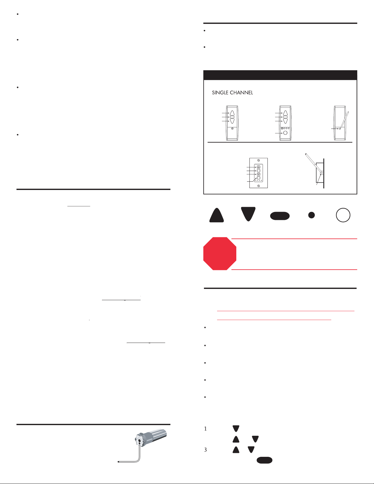
UP
FRONT
STOP
DOWN
CHANNEL
SELECTOR
STOP
SET
CHANNEL
SELECTOR
UP
STOP
DOWN
FRONT
STOP
SET
CHANNEL
SELECTOR
PROGRAMMING
BUTTON
FRONT SIDE
REMOTE CONTROL REFERENCE
How to Change Limit Settings
•
Only one shade should have power. If more than one
unit is plugged in, each one will be changed!
u have more than one motorized shade,
they must be set individually.
Apply power to one unit. Go through the setup
sequence. Then remove power.
All motor feedback is signaled by a visual jog.
(A jog is a short up and down movement).
If the shade does not work, press the program button
If the shade does not work, proceed to Motorized
Shade Programming on the reverse side.
until shade jogs up and down
to move shade to new position
(120 VAC / 60 Hz / 1.1 AMP)
All wiring must conform to NEC (National
Electrical Code) and local codes.
The motors can be wired in PARALLEL.
A means of disconnecting the power to each motor
independently should be provided.
STOP If shade(s) are operating properly,
go no further. Limits are preset at the
factory.