Solark 30K-3P-N User manual


March 2nd, 2023 1
UPON RECEIVING SHIPMENT ................................................................................................................................. 4
SPEC SHEET............................................................................................................................................................ 5
WIRE GAUGE GUIDE (COPPER)............................................................................................................................... 7
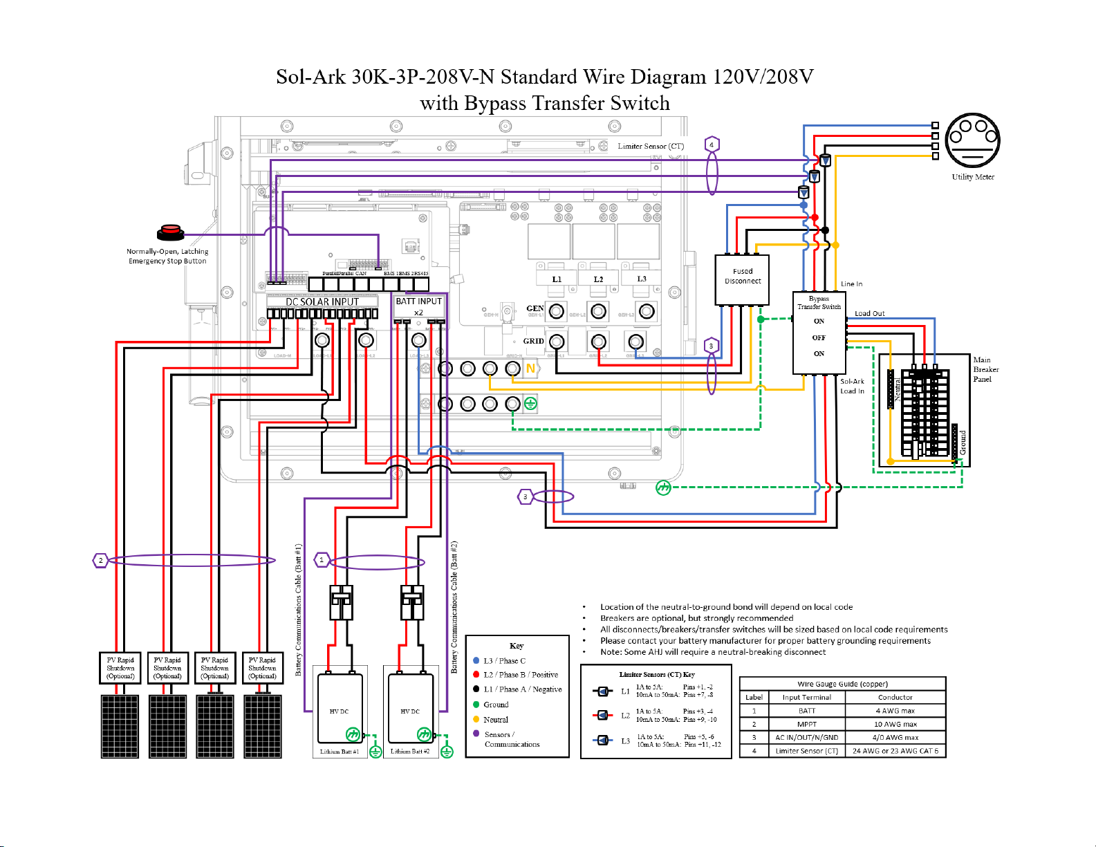
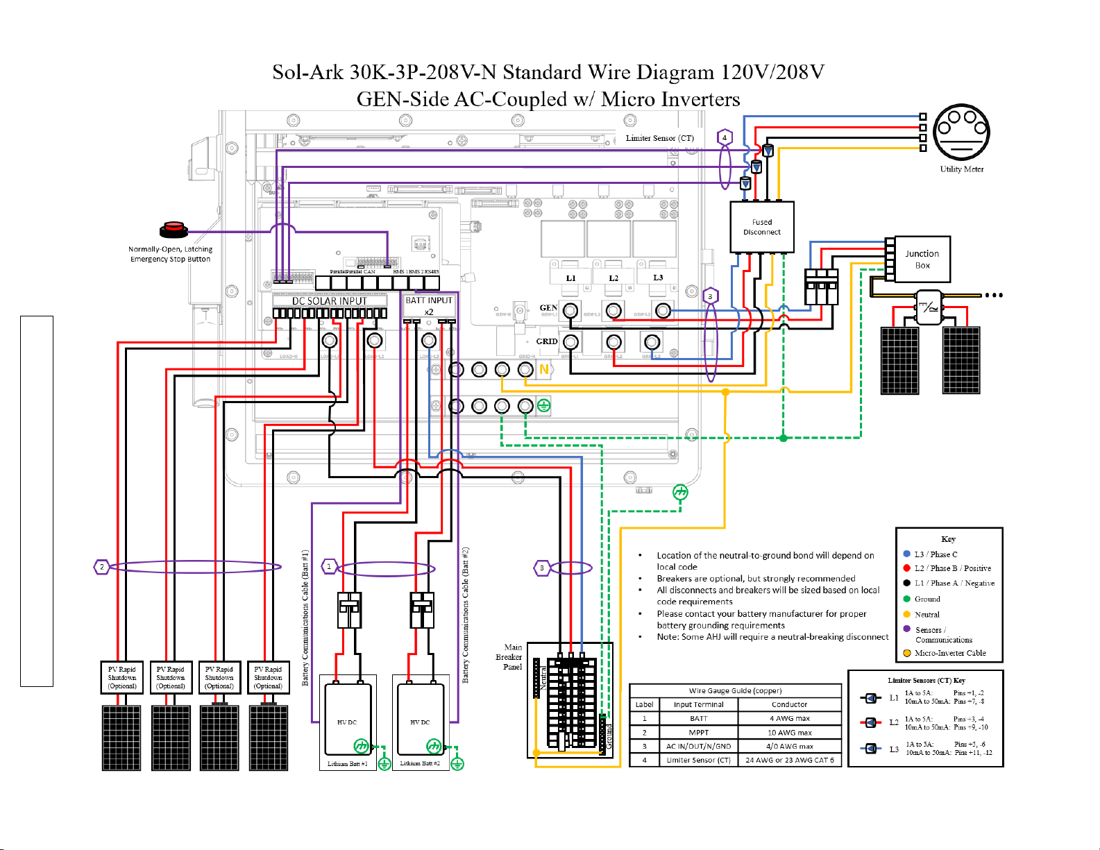
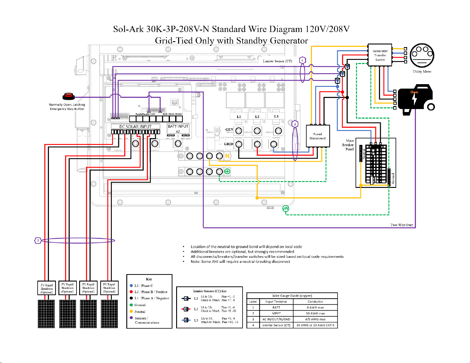
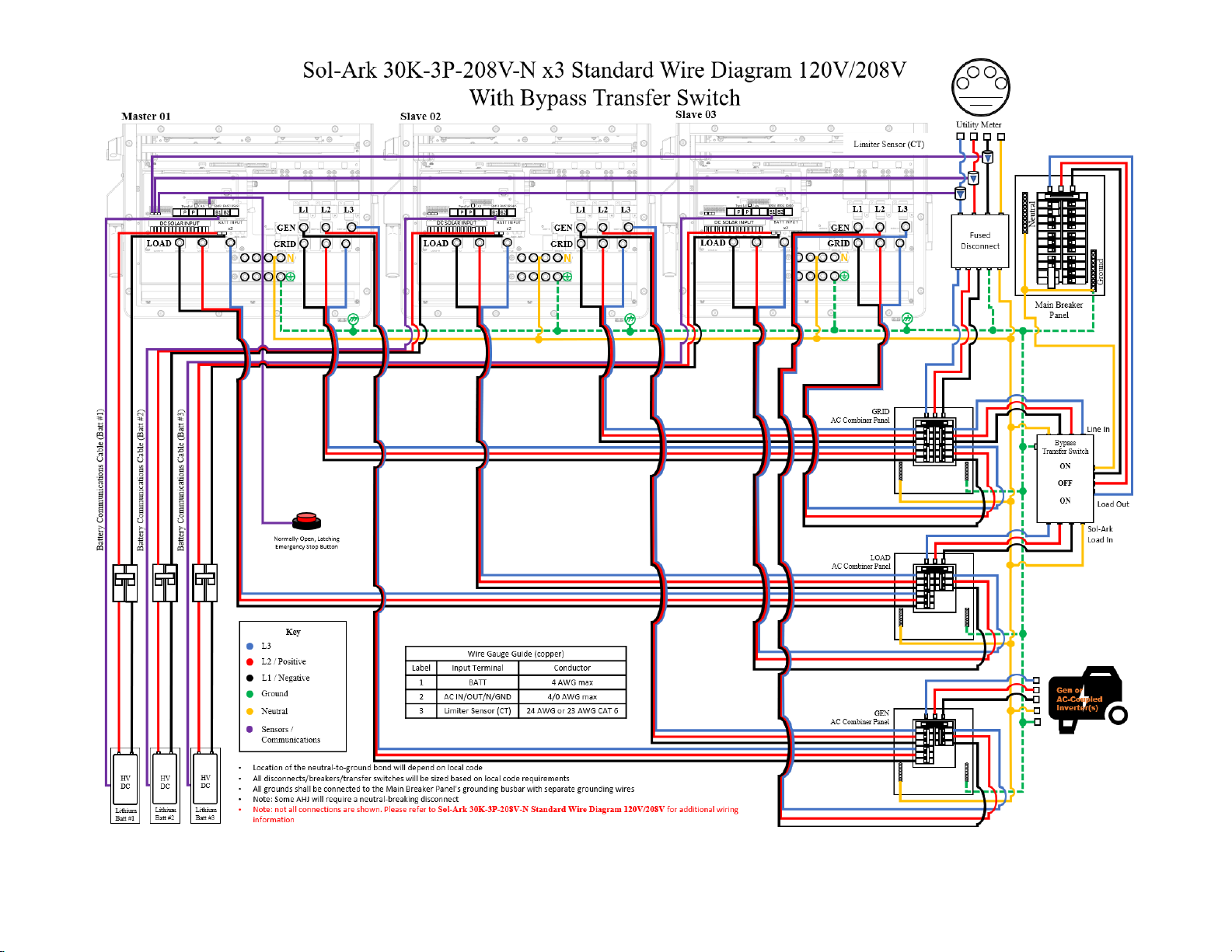
WIRING DIAGRAMS ............................................................................................................................................... 8
PHYSICAL INSTALLATION ..................................................................................................................................... 18
INVERTER COMPONENTS................................................................................................................................................18
DECIDING THE SITE’S BACKUP CIRCUITS............................................................................................................................18
SINGLE SYSTEM INSTALLATIONS (SMALL COMMERCIAL BACKUP) ...........................................................................................19
MOUNTING THE SOL-ARK..............................................................................................................................................19
INTEGRATING BATTERIES (SOL-ARK POWERED "OFF").....................................................................................................19
CONNECTING SOLAR PANELS ..........................................................................................................................................20
INTEGRATING A GENERATOR...........................................................................................................................................21
SENSORS INTEGRATION AND ACCESSORY PLACEMENT..........................................................................................................22
POWERING-UP &TESTING THE SOL-ARK 30K-3P-208V ....................................................................................................24
CHECK THE VOLTAGE ON EACH PV INPUT CIRCUIT ...............................................................................................................24
WI-FI / INTERNET CONNECTION........................................................................................................................... 25
REMOTE MONITORING SETUP ........................................................................................................................................25
IP ADDRESS SETUP INSTRUCTIONS (PC OR SMARTPHONE)...................................................................................................28
GUI SCREENS........................................................................................................................................................ 30
PROGRAMMING GUIDE ....................................................................................................................................... 32
MAIN SCREENS (TOUCHSCREEN).....................................................................................................................................33
BASIC SETUP ...............................................................................................................................................................34
SYSTEM ALARMS..........................................................................................................................................................34
BATTERY SETUP ...........................................................................................................................................................35
LIMITER TAB /GRID SETUP ............................................................................................................................................37
LIMITER SENSORS (CT SENSORS).......................................................................................................................... 41
LIMITER SENSOR AUTOMATIC SETUP ...............................................................................................................................41
INSTALL TIPS ........................................................................................................................................................ 43
OFF-GRID INSTALL TIPS.................................................................................................................................................43
GRID-TIE /NO BATTERY INSTALL TIPS ..............................................................................................................................43
BATTERIES ........................................................................................................................................................... 44
BATTERY CHARGING INFORMATION .................................................................................................................................44
TROUBLESHOOTING GUIDE.................................................................................................................................. 45
TROUBLESHOOTING PHASING ISSUES................................................................................................................................47
SOL-ARK 30K-3P-208V ERROR CODES ...........................................................................................................................48
INSTALL VERIFICATION CHECKLIST ....................................................................................................................... 49
30K-3P-208V LIMITED WARRANTY....................................................................................................................... 50
UL Model “30K-3P-208V”INSTALL GUIDE & OWNER’S MANUAL
30K-3P-208V
OUTDOOR

March 2nd, 2023 2
Disclaimer
UNLESS SPECIFICALLY AGREED TO IN WRITING, SOL-ARK:
(a) MAKES NO WARRANTY REGARDING THE ACCURACY, SUFFICIENCY, OR SUITABILITY OF ANY TECHNICAL
OR OTHER INFORMATION PROVIDED IN ITS MANUALS OR OTHER DOCUMENTATION.
(b) ASSUMES NO RESPONSIBILITY OR LIABILITY FOR LOSS OR DAMAGE, WHETHER DIRECT, INDIRECT,
CONSEQUENTIAL, OR INCIDENTAL, WHICH MIGHT ARISE OUT OF THE USE OF SUCH INFORMATION. THE USE
OF ANY SUCH INFORMATION WILL BE ENTIRELY AT THE USER'S RISK.
Sol-Ark cannot be responsible for system failure, damages, or injury resulting from improper installation of
their products.
The information included in this manual is subject to change without notice.

March 2nd, 2023 3
Warning Symbols
This symbol indicates information that, if ignored, could result in minor injury or
damage to the equipment.
This symbol indicates information that, if ignored, could result in serious injury,
damage to the equipment, or death.
This symbol indicates information that is important but not hazard-related.
Warnings
Read this entire document before installing or using the Sol-Ark 30K-3P-208V Inverter. Failure to
follow the instructions or warnings in this document can result in electrical shock, serious injury, or
death. Damage to the Sol-Ark Inverter is also possible, potentially rendering it inoperable.
High Life Risk Due to Fire or Electrocution –ONLY qualified personnel should install the Sol-Ark 30K-
3P-208V Inverter.
The system must have Ground connections and Neutral connections. Ground MUST be bonded to
Neutral ONLY ONCE in the circuit.
Solar PV+/PV- are UNGROUNDED. Note: you may ground PV Racking/Mounts, but doing so directly
to the Sol-Ark will likely result in damage in the case of a direct lightning strike to the PV array.
We recommend grounding the frames outside of the Sol-Ark circuit.
DO NOT connect the grid to the Load Output Terminal Block.
DO NOT reverse the polarity of batteries. Damage WILL occur.
DO NOT exceed 500Voc on any MPPT on the Sol-Ark.
DO NOT turn off the battery breaker if any current flows in or out of the battery.
DO NOT use impact drivers to tighten any fasteners on the Sol-Ark.
MUST use Strain Reliefs ON ALL wires entering/exiting the Sol-Ark 30K-3P-208V user area.
MUST use conduit (or double insulated wire) for AC Wires entering/exiting Sol-Ark 30K-3P-208V user
area.
ALL terminals/breakers, including battery, MPPT, and AC Terminal Block inputs, should only have
one conductor connecting to them.

March 2nd, 2023 4
Upon Receiving Shipment
Inspect Shipment
A. Compare the package condition to the condition of the package in the photo we sent you
before it left our facility.
B. If damaged, contact us immediately at 972-575-8875 Ext. 3
Component Guide—the following items are included in the package:
A. Sol-Ark 30K-3P-208V inverter (x 1)
B. Mounting Bracket: For wall mounting the Sol-Ark 30K-3P-208V (x 1)
C. Bolts M12x60 (x 4)
D. Bolts M4x12 (x 9)
E. CAT 5 cable for parallel communications (x 2)
F. WIFI Dongle: For software updates and remote monitoring (use M4x10 screws to hold in)
G. L-Type Hex Key (3mm): For opening and closing the user wiring area (x 1)
H. Included Limiter Sensors: 1 3/8” CT sensors (x 3)
I. T-Type Hex Key: For tightening the AC connections (x 1)
You must note any damage due to shipping with delivery driver before
accepting the package otherwise the shipping company will deny any claim.

March 2nd, 2023 5
Spec Sheet

March 2nd, 2023 6
Sol-Ark 30K-3P-208V Torque Values Application Note
Load Terminal Block
62 IN Lbs
7 NM
Grid Terminal Block
62 IN Lbs
7 NM
Gen Terminal Block
62 IN Lbs
7 NM
Neutral / Ground Busbars
62 IN Lbs
7 NM
Cover Screws
15.5 IN Lbs
1.75 NM
Battery Connection
Hand-Pressed Actuation Lever
2” Minimum Horizontal Clearance | 6” Minimum Vertical Clearance
2”(5.08cm)
Temperature Derating
DC: 90C-100C Shutdown @ 100C
AC: 75C-82C Shutdown @ 82C
Do Not Use Impact Drivers to Tighten Any Fasteners on the Sol-Ark.
2” (5.08cm)

March 2nd, 2023 7
Wire Gauge Guide (copper)
PV input: 12 - 10 AWG
AC Inputs/Outputs: 1/0 AWG - 4/0 AWG
All Sensors: 20 –24 AWG
CT Sensors: 10' Wire Included
Batt Temp Sensor: 6' Wire Included
RJ45 Cable: 7' Included (Extendable up to 20')
Battery input: 6 –4 AWG (Hand-Tightened
Actuation Lever)
400A: 2.0A
+
-
50.8mm (2in)
+
-
34.93mm (1 3/8in)
300A:5A
Fits 4/0 AWG
Regular
Limiter Sensor
Inputs
DC Battery Input
0’ –12’: 6 AWG
12’ –20’: 4 AWG
15.875mm (5/8in)
10 AWG Max
PV Panel Inputs
0’ –100’:
12 AWG
100’ –300’: 10 AWG
All Sensor Inputs
0’ –100’: 24 AWG (Do NOT use > 20AWG)
100’ –400’: 23 AWG CAT 6
CT Wires Can Be Extended -Extensions for Limiter
Sensors must be twisted pair (See pg. 41)
(Shielded CAT6 Recommended)
6.35mm
(1/4in)
20 AWG Max
Max
Grid + Load L1/L2/L3, Ground, & Neutral:
4/0 AWG
Gen L1/L2/L3, Ground, Neutral: 2/0 AWG
Distance Limits Will Vary Per User
25.4mm (1in)
4/0 AWG Max
Fits Metal Busbar
Grid Feed
X-Large
Limiter Sensor
25.4mm
(1in)
4 AWG Max
Max

March 2nd, 2023 9
CT Sensors are optional but necessary to enable
Peak Shaving.
See Integrating Gens and pg.41 for additional info.
Diagram 2

March 2nd, 2022 10
Diagram 3

March 2nd, 2022 11
Diagram 4

March 2nd, 2022 12
Diagram 5

March 2nd, 2022 13
Note: PV fuses are only required for >2 strings per MPPT
Diagram 6

March 2nd, 2022 14
Diagram 7

March 2nd, 2022 15
Diagram 8

March 2nd, 2022 16
Diagram 9
Note: Before powering up Parallel System installs, please see Pg. 46

March 2nd, 2022 17
Diagram 10
Note: Before powering up Parallel System installs, please see Pg. 46

March 2nd, 2023 18
Physical Installation
Inverter Components
1. Inverter Indicators
2. LCD Display (Touch)
3. Function Buttons
4. ON/OFF Button
5. 2 x PV Disconnect
6. Meter Port (optional)
7. Parallel Port
8. CAN Port
9. Ground / Neutral Bars
10. BMS Port
11. RS485 Port
12. Generator Input
13. Grid Connection
14. Function Port
15. PV Input MPPTs
16. Wi-Fi Interface
17. Load Connection
18. Battery Connections
Deciding the Site’s Backup Circuits
A. Ensure you keep the Inverter within its amperage limits
•ON-Grid = 200A passthrough (160A software limitation)
•OFF-Grid = 30kW = 83.4A Continuous | 45kVA = 125A Peak (10s)
B. Verify each load circuit by measuring typical and max Amps with a clip-on Amp meter. Amps x 120V = Watts
C. Install a subpanel for backup loads if there is a chance of exceeding any amperage limits while powering the
entire site off-grid; failure to do so will result in an outage and potential damage to the Inverter
D. If you have Arc-Fault / GFI breakers, DO NOT use a multi-circuit transfer switch.

March 2nd, 2023 19
Single System Installations (Small Commercial Backup)
A. Use the output from 200A Fused Disconnect (from the grid) for the Grid input connection to the Sol-Ark
B. Connect the Load output from the Sol-Ark directly to the Main Service Panel (at least 2/0 AWG)
C. Connect a Generator (150A @ 120V x3) or AC-Coupled system to the GEN terminal blocks
Mounting the Sol-Ark
A. Keeping in mind Sol-Ark's dimensions, find a suitable location for the system(s)
B. NEMA 3R rating for Outdoor installations
C. PROTECT the LCD screen from excessive UV exposure
D. System weight = 172 lbs (78kg). Securely attach to the wall. You may affix a mounting
board to studs using 6-8 long wood screws
E. Use the four (4) bolts + washers provided to mount the French Cleat to the board/wall
F. Mount Sol-Ark on the installed French Cleat / Ensure Sol-Ark is level and sits properly
G. Secure with the six (6) small screws (from 9 provided) for both sides of the French Cleat
Integrating Batteries (Sol-Ark POWERED "OFF")
A. Connect batteries to Sol-Ark as shown below
B. Ensure the external battery disconnect is OFF while connecting batteries, or arcing may occur
C. The 30K-3P reaches a maximum of 100A battery charge/discharge when using both battery terminals. When
using one set of terminals, the max battery charge/discharge is 50A
Multi-System Installs*
Please contact Sol-Ark technical support for parallel operation details.
Sol-Ark 30K-3P-208V is a High Voltage
Battery system. Do NOT wire the battery
bank to any other nominal voltage.
When using 48V batteries, do not exceed
eight (8) batteries in series.
Stay within the voltage range:
MIN 160V-MAX 500V
Do NOT reverse
polarity of batteries!
Damage will occur!
Do NOT pull actuation levers more than 45 degrees
away from vertical when installing the batt cables
Table of contents
Other Solark Inverter manuals

Solark
Solark L8K-2P User manual

Solark
Solark 8K-2P-L User manual

Solark
Solark 5K-1P-N User manual

Solark
Solark 5K-IP-N Assembly instructions

Solark
Solark 60K-3P-N User manual

Solark
Solark 8K User manual

Solark
Solark 12K User manual

Solark
Solark SA-5K-1P Assembly instructions

Solark
Solark LATAM 12K-3P-L Troubleshooting guide

Solark
Solark 5K User manual

Solark
Solark 5K User manual

Solark
Solark 8K User manual

Solark
Solark 12K User manual

Solark
Solark 5K-2P-N User manual

Solark
Solark 8K-2P-N User manual

Solark
Solark 8K-1P-N Assembly instructions

Solark
Solark 8K-P User manual

Solark
Solark L12K-Tr User manual

Solark
Solark 5K-P User manual

Solark
Solark 5K-2P-N Assembly instructions