Solark SA-5K-1P Assembly instructions
Copyright ©2023 Sol-Ark | Portable Solar LLC 1
EN
INSTALLATION GUIDE
AND USER MANUAL
Jun 15, 2023
RESIDENTIAL
NORTH AMERICA
V1.1
EN

2 Copyright ©2023 Sol-Ark | Portable Solar LLC

Copyright ©2023 Sol-Ark | Portable Solar LLC 3
EN
READ THE INSTRUCTIONS COMPLETELY BEFORE OPERATING
THE EQUIPMENT
Check the utility voltage before turning ON the unit.
Turn ON and program the unit using only batteries.
The unit will be programmed in 120V at a frequency of
60Hz by default.
Disregarding these instructions could result in permanent damages to the unit
DISCLAIMER
UNLESS SPECIFICALLY AGREED TO IN WRITING, SOL-ARK:
(A) DOES NOT WARRANT THE ACCURACY, SUFFICIENCY OR SUITABILITY OF ANY TECHNICAL OR OTHER INFORMATION PROVIDED IN
ITS MANUALS OR OTHER DOCUMENTATION.
(B) ASSUMES NO RESPONSIBILITY OR LIABILITY FOR ANY LOSS OR DAMAGES, WHETHER DIRECT, INDIRECT, CONSEQUENTIAL, OR
INCIDENTAL, ARISING OUT OF THE USE OF SUCH INFORMATION. USE OF SUCH INFORMATION SHALL BE ENTIRELY AT THE USER’S RISK.
Sol-Ark is not responsible for system failure, damage or injury resulting from improper installation of its products.
Information in this manual is subject to change without notice.
This manual is only focused on the inverter labeled as: 5K-1P-N.
Verificar el tipo de red antes de
encender la unidad.
Encender y programar usando
únicamente baterías.

4 Copyright ©2023 Sol-Ark | Portable Solar LLC
Table of Contents
IMPORTANT SAFETY INSTRUCTIONS ...........................................................................................................................................................................................................5
1. Sol-Ark: First Glance ..........................................................................................................................................6
1.1 General Description....................................................................................................................................................................................................................................7
1.2 Specifications...............................................................................................................................................................................................................................................8
1.3 Wire Gauge Guide....................................................................................................................................................................................................................................10
2. Installation........................................................................................................................................................ 11
2.1 Mounting the Sol-Ark ...............................................................................................................................................................................................................................11
2.2 Integrating Batteries.................................................................................................................................................................................................................................13
2.3 Ground Connection..................................................................................................................................................................................................................................14
2.4 PV Panels Connection ..............................................................................................................................................................................................................................14
2.5 Integrating a Generator ...........................................................................................................................................................................................................................15
2.6 Grid Peak-Shaving ....................................................................................................................................................................................................................................15
2.7 Automatic Generator Start.......................................................................................................................................................................................................................16
2.8 Integrating Sensors and Accessories.....................................................................................................................................................................................................16
2.9 Limit Sensor (CT sensor) ..........................................................................................................................................................................................................................17
2.10 Powering-up and Testing the Sol-Ark .................................................................................................................................................................................................19
2.11 Power Cycle sequence...........................................................................................................................................................................................................................20
2.12 LED Indicators .........................................................................................................................................................................................................................................20
2.13 Main screen (Touchscreen) ...................................................................................................................................................................................................................20
3. User Interface................................................................................................................................................... 22
3.1 Basic Setup.................................................................................................................................................................................................................................................22
3.2 Battery Setup .............................................................................................................................................................................................................................................23
3.3 Limiter .........................................................................................................................................................................................................................................................25
3.4 Grid Setup ..................................................................................................................................................................................................................................................29
3.5 Programming Guide.................................................................................................................................................................................................................................30
4. Installation Tips ............................................................................................................................................... 31
4.1 Battery Charge Controller .......................................................................................................................................................................................................................31
4.2 Battery Communication with MODBUS/CANBUS...............................................................................................................................................................................32
4.3 Grid Compliance Settings .......................................................................................................................................................................................................................33
5. Parallel Systems .............................................................................................................................................. 34
5.1 Before Enabling Parallel Operations .....................................................................................................................................................................................................34
5.2 Parallel Systems Programming Sequence ............................................................................................................................................................................................35
6. Wi-Fi / Ethernet Connection.......................................................................................................................... 36
6.1 Ethernet Connection ................................................................................................................................................................................................................................36
6.2 Wi-Fi (PC or Smart Phone) .......................................................................................................................................................................................................................36
7. Wiring Diagrams ............................................................................................................................................. 41
8. Troubleshooting Guide.................................................................................................................................. 47
8.1 Sol-Ark Error Codes..................................................................................................................................................................................................................................49
9. Install Verification ........................................................................................................................................... 50
9.1 Warranty Checklist....................................................................................................................................................................................................................................50
9.2 Limited Warranty: Sol-Ark 5K-1P-N........................................................................................................................................................................................................51
10. GUI Screens ................................................................................................................................................ 52
Copyright ©2023 Sol-Ark | Portable Solar LLC 5
EN
IMPORTANT SAFETY INSTRUCTIONS
SYMBOLS THAT APPEAR IN THIS DOCUMENT
WARNING: This symbol indicates information that, if ignored, could cause serious injury, equipment damage, or death.
CAUTION: This symbol indicates information that, if ignored, could result in minor injury or equipment damage.
NOTE: This symbol indicates relevant information that is not related to hazardous situations.
WARNINGS
Read this entire document before installing or using the Sol-Ark 5K-1P-N inverter. Failure to follow any of the instructions or warnings
in this document can result in electrical shock, serious injury, or death. Damage to the inverter is also possible, potentially rendering it
inoperable.
High Life Risk Due to Fire or Electrocution –ONLY qualified persons should install the Sol-Ark inverter.
The system must have Ground connections and Neutral connections. Ground MUST be bonded to Neutral ONLY ONCE in the circuit.
Solar PV+/PV- are UNGROUNDED. Note, you may ground PV Racking/Mounts, but doing so directly to the Sol-Ark will likely result in
damage in the case of a direct lightning strike to the PV array.
DO NOT connect the grid to the Load Output Terminal Block.
DO NOT reverse the polarity of batteries. Damage WILL occur.
DO NOT exceed 500Voc on any MPPT on the Sol-Ark.
DO NOT use impact drivers to tighten any fasteners on the Sol-Ark.
MUST use Strain Reliefs ON ALL wires entering/exiting the Sol-Ark user area.
MUST use conduit (or double insulated wire) for AC wires entering/exiting Sol-Ark user area.
ALL terminals/breakers, including battery, MPPT, and AC Terminal Block inputs, should only have one conductor connecting to them.
6 Copyright ©2023 Sol-Ark | Portable Solar LLC
1. Sol-Ark: First Glance
INSPECT SHIPMENT
The box should include all items shown in the component guide. If there is damage or missing parts, immediately call the phone number
(USA) +1 (972) 575-8875 Ext. 2.
COMPONENT GUIDE
The Sol-Ark 5K-1P-N system includes the following components:
Component
Description
Quantity
A
5K-1P-N inverter
1
B
French Cleat
1
C
Expansion plugs for concrete M8x80mm
4
D
CAT 5E communication cable
1
E
Allen key (2.4 mm)
1
F
Temperature sensor
1
G
User manual
1
H
Wi-Fi / Ethernet antenna (dongle)
1
I
Current transformer (CT sensors)
1
A
B
C
D
E
F
G
H
I

Copyright ©2023 Sol-Ark | Portable Solar LLC 7
EN
1.1 General Description
Component
Name
Component
Name
A
ON / OFF Button
H
PV DC disconnect
B
LCD touch screen
I
Wi-Fi / Ethernet dongle
C
Battery terminals
J
BMS RJ45 ports (RS485 / CAN)
D
Parallel RJ45 ports
K
MPPT inputs
E
Input pinouts for sensors
L
(33A) GEN terminal
F
NEUTRAL breaker
M
(50A) LOAD terminal
G
Internal AC conductors
N
(50A) GRID terminal
A
B
C
D
E
F
H
I
I
L
M
N
K
J
G
8 Copyright ©2023 Sol-Ark | Portable Solar LLC
1.2 Specifications
SOL-ARK 5K-1P-N TORQUE VALUES APPLICATION NOTE
Terminal
Torque [in-lb]
Torque [Nm]
“GEN”
17 in-lb
2 Nm
“LOAD”
17 in-lb
2 Nm
“GRID”
17 in-lb
2 Nm
Cover Screws
26.5 in-lb
3 Nm
Battery Connection
40 in-lb
4.5 Nm
Do not use impact drivers to tighten any fasteners on the Sol-Ark
Temperature derating
Optimum: -25°C to 60°C
Derating: >45°C
DC: Shutdown @100°C
AC: Shutdown @82°C
Copyright ©2023 Sol-Ark | Portable Solar LLC 9
EN
North America: 5K-1P-N
Datasheet
5K-120V/8K-230V-1P
Input Data (PV)
Max. Allowed PV Power (STC)
10,400W
Nominal Voltage Range
150 - 425V
Startup Voltage
125V
Max. Input Voltage
500V
Input Current per MPPT
Max. 26A (self-limiting 20A)
No. of MPP Trackers
2
No. of PV Strings per MPPT
2
Output Data (AC)
5K
8K
Nominal AC Voltage
120V Single Phase
240V Single Phase
Real Power, max continuous
4,800W
8,000W
Max. Output Current
40A
33.3A
Peak Apparent Power (5s, off-grid)
7,200VA
12,000VA
Additional AC Output Voltages (single phase)
127V –220V –230V
Grid Frequency
50 / 60Hz
Max. Grid Passthrough Current
50A
Power Factor Output Range
+/- 0.8 adjustable
Backup Transfer Time
5ms
Max Efficiency
97.6%
Sell Back Power Modes
Limited to Household / Fully Grid-Tied
Design (DC to AC)
Transformerless DC
Stackable
Up to 8 in parallel
Battery Input Data (DC)
Battery Technologies
Lithium / Lead Acid
Nominal DC Voltage
48V
Operating Voltage Range
40 - 60V
Capacity
50 —9900Ah
Max. Battery Charge / Discharge Current
120A
Charging Controller
3-Stage with Equalization
Grid to Battery Charging Efficiency
96.0%
External Temperature Sensor
Included
Current Shunt for Accurate % SOC
Integrated
Automatic Generator Start
Integrated
Communication to Lithium
CANBus & RS485
General Data
Dimensions (H x W x D)
600 x 330 x 237 mm / 23.6 x 13 x 9.3 in
Weight
24 kg / 53 lb.
Enclosure
IP65 / NEMA 3R
Ambient Temperature
-40~60°C, > 45°C Derating
Noise
< 30 dB
Idle consumption - No Load
60W
Installation Type
Wall-Mounted
Wi-Fi & LAN Communication
Included
Standard Warranty
5 Years
Protection and Certifications
PV Input Lightning Protection
Yes
Sell Back —UL1741-2010/2018, IEEE1547a-2003/2014
Yes
Anti-Islanding Protection
Integrated
PV String Input Reverse Polarity Detection
Integrated
Insulation Resistor Detection
Integrated
Residual Current Monitoring Unit
Integrated
Output Over Current Protection
Integrated
Output Shorted Protection
Integrated
Surge Protection
DC Type II / AC Type II
2023 Sol-Ark | Portable Solar LLC Support: (972) 575-8875 Ext. 2, support@sol-ark.com Sales: (972) 575-8875 Ext. 1, sales@sol-ark.com
10 Copyright ©2023 Sol-Ark | Portable Solar LLC
1.3 Wire Gauge Guide
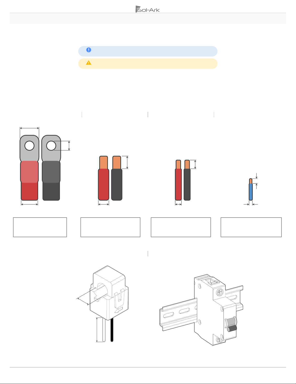
1. AC INPUTS / OUTPUTS:
•“GRID”Terminal 50A MAX 50A passthrough, 6 AWG conductor.
•“LOAD” Terminal 50A MAX 50A passthrough, 6 AWG conductor.
It is possible to use 10AWG conductors if using the inverter for grid sell only.
Wire gauge should be selected in compliance with your local electrical code.
2. SENSORS: 24-20 AWG
3. SENSORS (CT): 13 ft [4 m] included
4. BATTERY TEMPERATURE SENSOR: Included 9.8 ft [3 m] sensor
5. CABLE RJ45: Included 6.5 ft [2 m]. Extendable up to 20 ft [6 m]
6. BATTERY CABLES: 2/0 AWG THHN / Max Charge and Discharge limited to 120A
Batteries
AC Conductors
PV Conductors
Sensors
CT Sensor (Included)
AC Breaker (Single pole)
1 in [25.4 mm]
6 AWG MAX
3/8 in
[10 mm]
1/4 in
[6.35 mm]
10 AWG MAX
20 AWG MAX
2/0 AWG MAX
Max distance
0’ - 12’ [3.5 m]: 2/0 AWG
12’ –20’ [6 m]: 4/0 AWG
Max distance
0’ –100’ [30 m]: 8 or 6 AWG
Max distance
0’ –100’ [30 m]: 12 AWG
100’ – 300’ [90 m]: 10 AWG
Max distance
0’ –100’ [30 m]: 24 AWG
100’ –400’ [120 m]: 23 AWG
5/8 in
[16 mm]
5/8 in
[16 mm]
5/8 in
[16 mm]
13 ft
[4 m]

Copyright ©2023 Sol-Ark | Portable Solar LLC 11
EN
2. Installation
Backup Circuits
A. The sub panel powered by the LOAD terminal will be considered the essential loads panel.
B. You must keep the essential loads panel within the limitations of the unit:
•Grid Tie 6 kW = 50A continuous @ 120V (passthrough).
•Off-Grid 4.8 kW = 40A @ 120V from batteries or PV.
C. Verify that every load circuit power P=V*I, does not surpass the aforementioned limits.
Single System Install
A. FOR PARTIAL BACKUP: Connect the output of your back-feed breaker or line side tap (depending on the point of interconnection)
to the "GRID" terminal. An external breaker of 50A MAX must be installed to protect the inverter and conductors.
B. FOR WHOLE-HOME BACKUP: Connect the grid directly to the “GRID” terminal. An external breaker of 50A MAX must be installed.
•Connect the “LOAD” terminal of the inverter to an external breaker. Then, connect the Main Service Panel to that external
breaker using 6 or 8 AWG conductors.
•It is possible to connect a generator or an AC coupled source (30A max or 3,600W) such as string or micro inverters to the
“GEN” terminal of the inverter. Only one AC source can be connected to the “GEN” terminal at a time.
C. An external battery breaker is required. External breakers must be sized according to local AHJ.
Partial Backup
Whole-Home Backup
Figure 1: Partial backup or whole-home backup installs
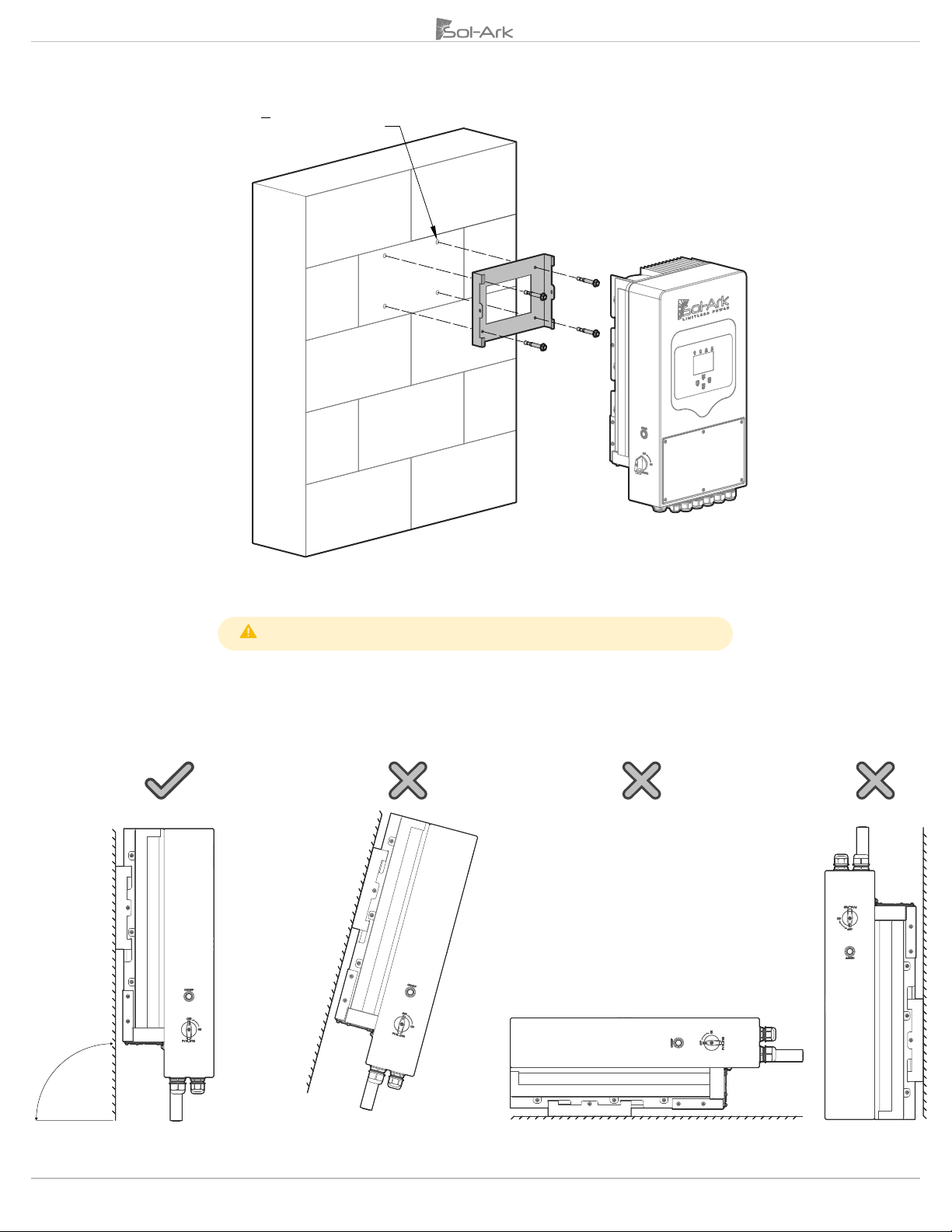
2.1 Mounting the Sol-Ark
A. System weight: 24 kg / 53 lb.
B. Considering the dimensions of the inverter, find a suitable location for the system(s).
There must be at least 6 in [15 cm] of vertical clearance for proper heat dissipation.
Heat transfer is done from bottom to top at a rate of 115.2 W/hr
C. The Sol-Ark 5K-1P-N is a NEMA 3R - IP65 enclosure, rated for outdoor installation but
can also be installed indoors.
D. PROTECT LCD screen from direct exposure to UV light.
E. Mount the Sol-Ark and ensure the unit is leveled and properly seated.
F. Securely attach to the surface. You may need expansion plugs/anchors for concrete. In
case a different anchorage is required, calculate the support needed to properly hold the
weight of the equipment.
G. Use four (4) screws and washers (choose screw length and surface type).
AC
DC
PV
Battery
Grid
Main Panel
Subpanel
PV
Battery
Grid
Main Panel
≥ 6 in
[15 cm]
≥ 6 in
[15 cm]
≥ 2 in
[5 cm]
≥ 2 in
[5 cm]
Figure 2: Unit clearances
12 Copyright ©2023 Sol-Ark | Portable Solar LLC
Figure 3: Wall Mount
Damage to the LCD Screen due to direct sunlight exposure will not be covered by warranty
H. Mount the inverter in the optimal orientation as shown below.
Figure 4: Best practice for mounting orientation
4X ø 7
16
“↧3” [80 mm]

Copyright ©2023 Sol-Ark | Portable Solar LLC 13
EN
2.2 Integrating Batteries
A. Sol-Ark 5K-1P-N must be OFF.
B. Depending on battery voltages, wire up the battery bank in the next possible configurations (see figures 5a-5c).
C. Internal battery breakers must be OFF when wiring. If your battery bank does not have internal breakers, maintain the necessary
safety measures when handling.
Sol-Ark 5K-1P-L is a 48Vdc nominal system. DO NOT connect the inverter to any other battery configuration. If you use 12V batteries,
you MUST NOT exceed four (4) batteries in series, as shown in Figure 5b. The inverter can work with any battery chemistry if it remains within
the range of 43V to 63V.
Figure 5a: 48V batteries in parallel connection
Figure 5b: Four 12V batteries in series connection
Figure 5c: Series and parallel connections for complete 48V batt bank
DO NOT reverse polarity. The system will be damaged, and warranty will
be voided!
IMPORTANT NOTE: Multi-System Install
A. ALL inverters in a parallel system MUST connect to a single battery bank. System will NOT function properly if this is not followed.
B. DO NOT use separate battery banks in parallel systems.
Figure 6: Single battery bank for parallel inverters

14 Copyright ©2023 Sol-Ark | Portable Solar LLC
2.3 Ground Connection
It is essential to add a grounding connection directly into the frame, with the goal of protecting the end user in case of experiencing any
failure on the original ground conductor.
Figure 7: Ground connection
When the system is installed in off-grid scenarios, the neutral must be connected to ground
2.4 PV Panels Connection
The inverter has 2 MPPTs that work independently from each other. Each MPPT will accept 20A (self-limiting) and a MAX Voc of 500V. Usable power per
MPPT of 2.4 kW (370Voc optimum value)
A. Max solar input = 10.4 kW (± 5%) | Max input per MPPT = 5.2 kW | Max input voltage per MPPT = 500 VOC | Max input current per
MPPT = 20A (self-limiting).
B. There will be damage if V > 500V
C. Strings in parallel on the same MPPT must have the same designed voltage (Voc), otherwise the system will be limited to the
lowest string voltage.
i. PV1 A/B must have the same Voc.
ii. If the solar panels are oriented in different directions and connected in the same MPPT, there will be a loss in PV efficiency.
D. It is recommended to ground the mounting frame of the PV array to an external grounding system.
E. Design for a max input current of 20A per MPPT. The inverter will self-limit beyond 20A. If current exceeds 26A Isc limit, damage
will occur.
F. Connect the solar panel strings using either of the following configurations:
“Y” connection
Individual strings
Figure 8: MPPT wiring and PV connections
AC Coupling
The Sol-Ark 5K-1P-N is a system that supports the addition of AC coupled solar panels. The solar input power can be expanded by coupling
micro or string inverters into the “GEN” or “LOAD” terminals. A full AC coupled solar system is not recommended as power control and
monitoring is limited. Having DC coupled modules or a combination of DC coupled and AC coupled solar panels is always preferred.
1. AC coupling on “GEN”
a. Can produce solar power during a grid outage or off-grid systems.
b. Can monitor solar production.
Connector-Y
Connector-Y
String PV1A
String PV1B
String PV1B
String PV1A
Copyright ©2023 Sol-Ark | Portable Solar LLC 15
EN
2. AC coupling on “LOAD”
a. Can produce solar power during a grid outage or off-grid systems.
b. Can NOT monitor solar production.
c. “GEN” input CANNOT be used.
In Off-Grid systems, Sol-Ark uses Frequency Shift technology to shut down AC coupled solutions when battery is full. Grid-Tied AC coupled solutions
will always sell excess solar power back to the grid. “Limited to Load” will NOT limit production when AC coupled.
2.5 Integrating a Generator
Generators Smaller than 3.6 kW On “GEN” Terminal
1. Supports single phase 120V, 240V generators. External 30A breaker must be installed to protect the inverter and conductors.
2. Connect the generator output to the “GEN” input terminal of the Sol-Ark 5K-1P-N.
3. A THD (Total Harmonic Distortion) of less than 15% is preferred.
Generators Bigger than 3.6 kW On “GRID” Terminal
1. Supports 120V, 240V generators.
2. Off-grid systems with whole-home generators on ATS (Automatic Transfer Switch) or manual transfer switch connected to the grid
input terminal require selecting “GEN Connect to Grid Input”.
a. Home Screen “Limiter”“Other”“🗹GEN Connect to Grid Input” “OK”
3. An Off-grid system should NOT use “Grid sell”. CT sensor on generator line is only needed if using “Grid Peak Shaving” to peak-
shave the generator.
Weekly Gen Exercise: If a generator has two-wire start compatibility, it will experience weekly generator tests. This test occurs at 8:00AM (local time)
every Monday by default. The test takes 20 minutes to complete. The generator will start and stop automatically. The test can be disabled by specifying
:00 | 00 min in the "Generator Exercise Cycle Day & Time" option.
Improve the Generator & Sol-Ark Compatibility
Select “General Standard”, in the “Grid Selection” tab under “Grid Mode”, then in the “Connect” tab under “Normal connect & Reconnect”,
increase the frequency range to “Grid Hz High=65Hz”, “Grid Hz Low=55Hz” to avoid disconnections between the generator & Sol-Ark 5K-
1P-N. Additionally, increase the voltage range to “Grid Volt High=130V” and “Grid Volt Low=110V”.
Sol-Ark will not charge the batteries using the generator unless the “Start V” or “Start %” condition is fulfilled. Only one condition (V or %) will be
modifiable depending on which control mode is selected (“Use Batt V Charged” or “Use Batt % Charged”)
2.6 Grid Peak-Shaving
1. To use Peak-Shaving for a generator, it must be connected to the “GRID”terminal.
2. Peak shaving prevents the Sol-Ark 5K-1P-N from overloading generators or can help cut
down on costs from utility grid.
3. Install the CT sensor so that it measures L1 of the generator/grid output. The arrow on the
CT must point toward the generator / grid.
4. Sol-Ark contributes power from the batteries above the “Power” threshold to prevent
overloading or to cut down on utility grid consumption.
5. This mode will automatically adjust the amperage (A) from “Grid Charge A”, to avoid
overloads.
6. Grid Peak-Shaving will automatically enable “Time of Use”. The “Time of Use” settings
must to be configured.
Figure 9: Grid peak-shaving setting
16 Copyright ©2023 Sol-Ark | Portable Solar LLC
2.7 Automatic Generator Start
1. “Gen Charge” is used when the generator is connected to the “GEN”terminal.
a. “Start V” or “Start %” is the set-point/condition that must be fulfilled to automatically start the generator.
b. To charge the battery from the “GEN” source, “Gen Charge” must be selected.
c. Batteries will charge from a generator until the battery bank accepts 5% of its programmed capacity in Amperes (A).
This is equivalent to around 95% of the SOC.
2. “Grid Charge” is used to charge the battery from the “GRID”terminal source (utility grid or a generator).
a. “Start V” or “Start %” is the set-point/condition that must be fulfilled to automatically start the generator.
b. To charge the battery from the “GRID” source, “Grid Charge” must be selected. This option keeps the battery at 100%.
c. Batteries will be charged to 100% from utility grid.
d. Batteries will charge from a generator until the battery bank accepts 5% of its rated capacity in Amperes (A). This is
equivalent to around 95% of the SOC
If “Time of Use”(“TOU”) is enabled, “🗹Charge” must be checked on desired time intervals. Otherwise, the generator won’t automatically start even if
the Start V or Start % condition has been met.
Gen Charge / Grid Charge “A”
“A” is how many amps (DC) are supplied to the battery from a generator. Adjusting and limiting the
GEN or GRID “A”value will ensure that small generators are not overloaded when charging the
battery bank.
If connecting more than one Sol-Ark in parallel, multiply the Gen or Grid “A”value by the # of Sol-
Ark inverters to get the actual current (A) what will go into the battery bank.
2.8 Integrating Sensors and Accessories
Figure 11: Inverter sensor pinouts
•(1,2) Battery temperature sensor: Not polarity sensitive. Used for voltage compensation for Lead Acid batteries
•(+3, -4) CT1: Current transformer (CT) input
•(5,6) Gen Start Relay: Two-Wire start, dry contact (normally open). Triggers emergency stop
•(7,8): Not in use
Temperature Sensor
•Place the sensor between two batteries as shown in the next figure.
•Secure with tape and place away from the batteries terminals to prevent overheating.
•This sensor has no polarity. The temperature sensor helps perform voltage charging
adjustments and capacity calculations due to changes in temperature.
•Lithium Batteries DO NOT require our external temperature sensor.
Figure 10: Generator and grid charge settings
Figure 12: Temperature sensor for
Lead-Acid batteries
Copyright ©2023 Sol-Ark | Portable Solar LLC 17
EN
BMS Port (CAN/RS485)
•This port is used to setup a Lithium Battery in closed-loop communication with the Sol-Ark 5K-1P-N (consult our “Battery
Communications Integration Guide”on the Sol-Ark website at www.Sol-Ark.com/support).
•Must use an RJ45 connector.
•Only use the CAN port for battery BMS communications (the CAN port supports both CANBus protocol and Modbus protocols)
Wi-Fi / Ethernet Antenna (Dongle)
•Remote monitoring and software updates require an internet connection through the Wi-Fi
Dongle.
•Compatible for Wi-Fi and ethernet connections.
GEN Start Signal (Two-Wire Start)
•Signal that comes from a normally open relay (5 & 6 sensor pinouts). Relay closes when the generator “Start” condition is met.
2.9 Limit Sensor (CT sensor)
The CT sensor (or limit sensor) enable the use and smooth operation of the system work modes known
as “Limited Power to Home” and “Grid Peak-Shaving”. The CT will measure and calculate the demand
in the Main Service Panel which the Sol-Ark 5K-1P-N will then use to accurately supply and offset all home
loads.
Off-Grid system do not require CT sensors unless using “Grid Peak-Shaving”
CT Sensor Installation
•Install sensor on incoming electrical service wires on L1.
•Embossed arrow on the sensor must point toward the grid.
•“Limited Power to Home” (Meter Zero) and “Grid Peak-Shaving” require CT sensors.
•To ensure proper fit, check incoming wire diameter (grid or generator). If the sensor is too small,
•See section 3.3 “Limiter” for more information about the different Sol-Ark work modes.
•See section 7 “Wiring Diagrams” for detailed CT installation.
Figure 15: Installation of CT
Meter
CT
Main Panel
Meter
CT
Main Panel
Figure 13: Wi-Fi dongle (antenna)
Figure 14: CT Sensor
18 Copyright ©2023 Sol-Ark | Portable Solar LLC
CT Sensor Size
•Sol-Ark includes one 5/8” CT sensor (100A for 2/0 AWG wire gauge).
•Sol-Ark offers 15/16” CTs (200A for 4/0 AWG wire gauge) and 2” CTs (400A) upon request.
•Default Sol-Ark CT ratio is 2000:1
Unless authorized, DO NOT change CT Ratio or warranty will be voided
Wire gauge is the only metric used to determine size of CTs. Contact sales at +1 (972) 575-8875 ex. 1 to purchase bigger CT sensors
Wiring the CT sensor
•Connect CT from phase L1 to pin 3 (white), 4 (black).
•Keep the wires twisted (white-black) throughout the connection.
•If the wires need to be extended, use CAT 6 (shielded) cable to make an extension (see Figure 17).
Figure 16: CT input pins on inverter
CT Sensors for Parallel Systems
•Each inverter will include one (1) CT sensor.
•Only one CT sensor must be wired to the designated “MASTER” inverter.
•CT sensors are essential for multi-Sol-Ark systems as “Limited Power to Home” mode is highly
recommended for multi-system installs.
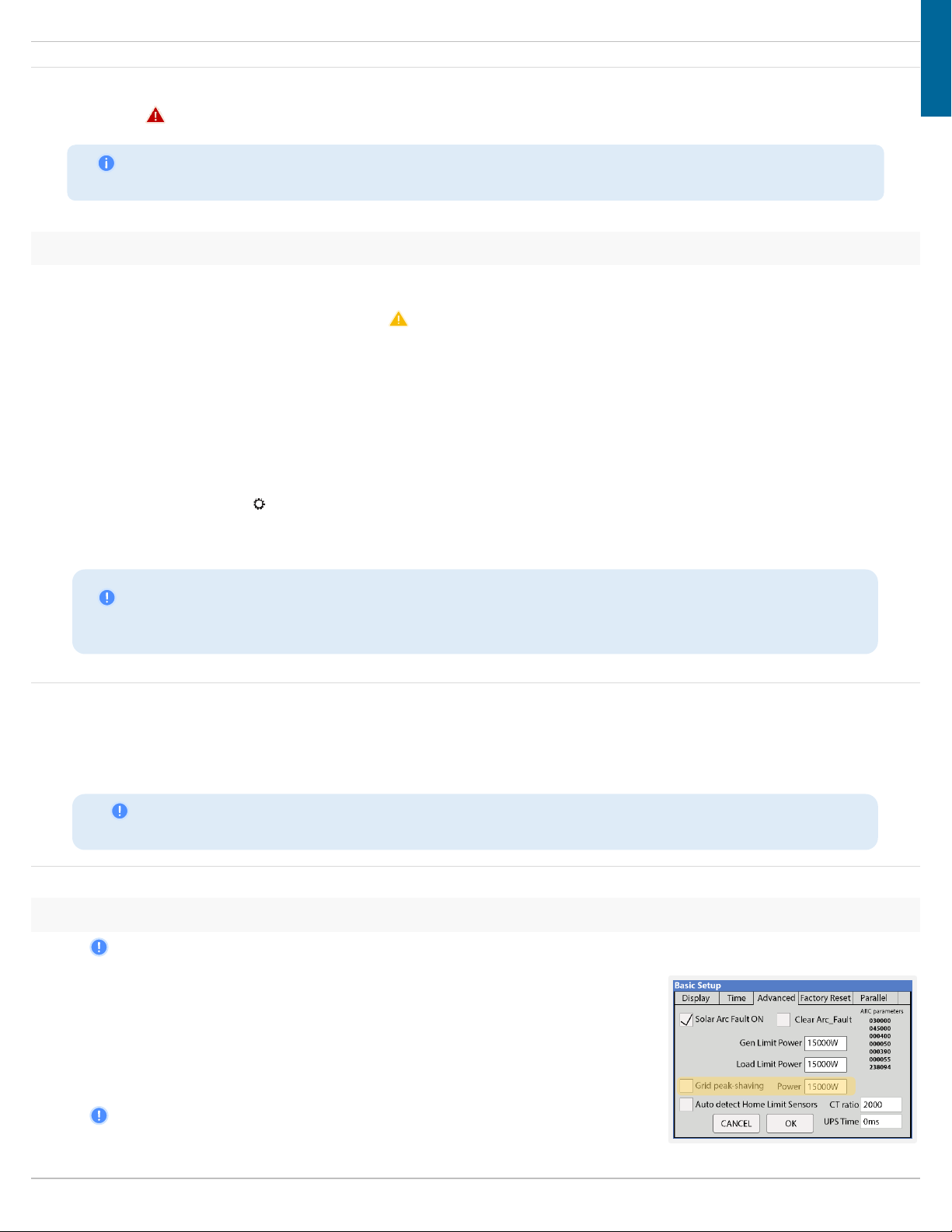
Automatic CT Limit Sensors Configuration
This function requires batteries to auto detect and auto correct CT orientation. AC coupled inverters need to
be OFF during the detection test. If this test is done with connected AC-coupled systems, a factory reset of
the Sol-Ark must be performed. Install the CT sensor as described in section 2.9 “Limit Sensor”. A battery
connection and grid power are required before starting the automatic configuration.
Basic Setup Advanced 🗹Auto detect Home Limit Sensors OK
Wait at least 10 to 15 seconds while the inverter performs the test. The inverter will alternate the current
distribution in L1, determining the correct orientation of the sensor.
CT sensor troubleshooting
•
If you are exclusively using “Limited power to Home”, HM values will read close to zero or positive. Keep in mind that all sensors
have a 3% error.
•
To avoid selling power to the utility use “Zero Export Power” equal to or greater than 20W.
•
Buying power from the grid will display positive (+) HM values, while selling to the grid displays negative (-) HM values.
+ -
Figure 17: CT wire extensions with
shielded CAT 6 cable
Copyright ©2023 Sol-Ark | Portable Solar LLC 19
EN
2.10 Powering-up and Testing the Sol-Ark
TURN ON the inverter with at least one power source: 1) Battery, 2) PV or 3) Grid
1. Check the voltage of the battery bank
A. Voltage of the battery must be between 40Vdc - 60Vdc.
B. If applicable, turn “ON” internal switches of battery modules or battery pack. Measure individual voltages.
C. Verify proper voltage of the battery bank at the battery terminals of the Sol-Ark.
2. Check the voltage of each PV input circuit
A. Input voltage must not exceed 500Vdc.
B. Input voltage must be above the startup voltage of 125Vdc.
C. Do not ground PV+ or PV-.
D. Verify polarity in each PV string. Backward polarity will measure 0Vdc or (-) Vdc. (May cause long term damage if not rectified).
E. PV input will only turn on the LCD screen. Inverter requires grid power and/or batteries to start inverting.
F. PV DC disconnect switch on the side of the inverter will turn the PV ON or OFF.
Figure 18: Built-in PV DC disconnect
3. Check GRID input voltage
A. Use the top screws above the terminals to measure AC voltages with a multimeter.
B. Measure line (L) to neutral (N) voltage on “GRID” terminal. Ensure 120Vac.
C. Verify that voltage between neutral (N) and ground (G) is 0Vac.
D. Verify that voltage between GRID L and LOAD L is 0Vac.
Figure 19: AC Terminals
4. Power ON Sol-Ark
A. Turn “ON” the external battery breaker. Wait for the “Normal” LED indicator to turn on. This may take a few minutes.
B. Turn “ON” the PV DC disconnect switch. Wait for “DC” LED indicator to turn on.
C. Turn “ON”the external “GRID”breaker. Wait for “AC” LED indicator to turn on.
D. Press the power button located on the side of the inverter.
E. Turn “ON” the external “LOAD”and “GEN”breakers.
OFF
ON
Figure 20: Power Button OFF / ON
OFF
ON
OFF
ON
9 flat head screws
L N G
GEN
L N G
LOAD
L N G
GRID
20 Copyright ©2023 Sol-Ark | Portable Solar LLC
2.11 Power Cycle sequence
1. Press the power button on the side of the inverter back to the OFF position.
2. TURN OFF all AC sources including the external GRID, GEN, and LOAD breakers.
3. TURN OFF the built-in PV DC disconnect switch on the side of the inverter.
4. TURN OFF the external battery disconnect.
5. Wait a moment (~1 min) to ensure the inverter is completely de-energized.
6. Make sure that the Sol-Ark is properly connected to the batteries, solar panels, grid, gen, and loads.
7. Reverse the steps to turn ON the inverter
2.12 LED Indicators
Figure 21: User interface and LED indicators
DC
AC
Normal
Alarm
Green DC Solar Panels
connected and providing
voltage.
Green Grid is connected
and providing voltage.
Green Sol-Ark is fully
energized* and inverting
power.
Red Alarm state. Check the
alarms menu. Home Screen
“System Alarms”
OFF Minimum MPPT
voltage not met, wrong
polarity or no PVDC.
OFF Grid voltage out of
range or Off-Grid system.
OFF Not fully energized*,
in fault state or in passthrough
mode.
OFF No alarms / error
codes / setting change
notifications
*Fully energizing the unit constitutes at least: a) DC Solar panels AND Grid or b) Just batteries
2.13 Main screen (Touchscreen)
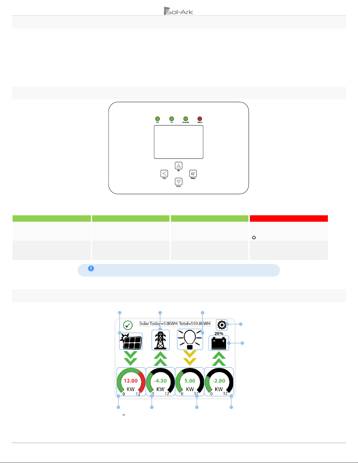
Figure 22: Main Screen
PV power generation graph
Hold 4 s to force Smart Loads
Settings
Details Screen
Solar power production
Grid power
Sell (+) / Buy (-)
Load power
consumption
Battery power
Charge (+) / Discharge (-)
Grid usage graph
This manual suits for next models
2
Table of contents
Other Solark Inverter manuals

Solark
Solark L8K-2P User manual

Solark
Solark 5K-IP-N Assembly instructions

Solark
Solark LATAM 12K-3P-L Troubleshooting guide

Solark
Solark 5K User manual

Solark
Solark 8K-1P-N Assembly instructions

Solark
Solark 8K User manual

Solark
Solark 12K User manual

Solark
Solark 8K-2P-L User manual

Solark
Solark 8K-2P-N User manual

Solark
Solark 5K User manual

Solark
Solark L12K-Tr User manual

Solark
Solark 8K User manual

Solark
Solark 8K-P User manual

Solark
Solark 5K-1P-N User manual

Solark
Solark 5K-2P-N User manual

Solark
Solark 5K User manual

Solark
Solark 8K User manual

Solark
Solark 60K-3P-N User manual

Solark
Solark 5K-P User manual

Solark
Solark 5K-2P-N Assembly instructions


