SolaX Power TBMS-MCS0800 User manual

SolaX Power Network Technology (Zhejiang) Co., Ltd.
Add.: No. 288, Shizhu Road, Tonglu Economic Development Zone, Tonglu City,
Zhejiang Province, 310000 P.R. China
Tel.: +86 (0) 571-5626 0011
E-mial: info@solaxpower.com
320101057700

Copyright © SolaX Power Technology (Zhejiang) Co., Ltd. All rights reserved.
No part of the document may be reproduced or transmitted in any form or by
any means without prior written consent of SolaX Power Technology (Zhejiang)
Co., Ltd. (hereinafter referred to as SolaX). SolaX reserves the right of final
interpretation.
www.solaxpower.com
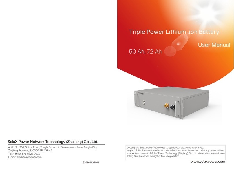
Triple Power Lithium-ion Battery
User Manual
50 Ah, 72 Ah


CHNAGE HISTORY
Changes between document versions are cumulative. The latest version contains
all updates made in previous versions.
Version 00 (Jan. 30, 2023)
Initial release

Content
1 Note on this Manual.......................................................................................... 1
1.1 Scope of Validity ............................................................................................1
1.2 Target Group ..................................................................................................1
1.3 Symbols............................................................................................................1
2 Safety...................................................................................................................2
2.1 Safety Instruction...........................................................................................2
2.1.1 General Safety Precautions ................................................................2
2.1.2 Explanation of Labels............................................................................3
2.2 Response to Emergency Situations...........................................................4
2.2.1 Leaking Batteries ...................................................................................4
2.2.2 Fire............................................................................................................4
2.2.3 Wet Batteries and Damaged Batteries..............................................4
2.3 Qualified Installer ..........................................................................................5
3 Production Information...................................................................................6
3.1 Dimensions and Weight ...............................................................................6
3.2 Installation Space ..........................................................................................8
3.3 Appearance.....................................................................................................9
3.4 Basic Features ...............................................................................................13
3.4.1 Features ..................................................................................................13
3.4.2 Certifications ..............................................................................................13
3.5 Specification...................................................................................................14
3.5.1 T-BAT-SYS-HV-S25................................................................................14
3.5.2 T-BAT-SYS-HV-S36 ...............................................................................16
4 Preparation before Installation.......................................................................18
4.1 Prerequisites....................................................................................................18
4.2 Safety Gear......................................................................................................19
4.3 Installation Tools............................................................................................19
4.4 Preparation ....................................................................................................20
4.4.1 Check for Transport Damage..............................................................20
4.4.2 Unpacking...............................................................................................20
4.4.3 Accessory ...............................................................................................21
5 Equipment Installation ....................................................................................24
5.1 Installation Environment Requirements....................................................24
5.2 Installation Procedure ..................................................................................25
6 Wiring ..................................................................................................................31
6.1 Current Terminal Connection.....................................................................31

6.2 Communication Connection (connecting to inverter).........................32
6.3 Cable Connection ........................................................................................33
6.3.1 Wiring without Series Box ..................................................................33
7 Commissioning .................................................................................................39
7.1 DIP Switch........................................................................................................39
7.2 Start and Shutdown Procedure ..................................................................40
7.3 Status Indicators.............................................................................................41
8 Troubleshooting................................................................................................44
9 Decommissioning .............................................................................................47
9.1 Dismantling Battery.......................................................................................47
9.2 Packing ............................................................................................................47
10 Maintenance ....................................................................................................48
11 Disclaimer .........................................................................................................49


1
1 Note on this Manual
1 Note on this Manual
1.1 Scope of Validity
This manual, an integral part of T-BAT Series, contains information on assembly,
commissioning, maintenance and failure of the device. Please read it carefully
before operation.
BMS
TBMS-MCS0800
Battery Module
TP-HS25, TP-HS36
Note: In case of one group, there are 3 parts of the T-BAT system, which includes
BMS, battery module(s) and base. In case of two groups, there 4 parts of the
system, such as, BMS, battery module(s), base and Series Box. For details, please
refer to 3.3.1 Configuration List on page.
1.2 Target Group
This Manual is designed for qualified electricians. The installation procedure
described in the Manual may only be performed by qualified electricians.
1.3 Symbols
There are several safety marks in the Manual. The detailed explanation is shown
as follows:
DANGER!
“DANGER” indicates a hazardous situation which, if not avoided, will
result in serious injury or death.
WARNING!
“WARNING“ indicates a hazardous situation which, if not avoided, could
result in serious injury or death.
CAUTION!
“CAUTION“ indicates a hazardous situation which, if not avoided, could
result in minor or moderate injury or death.
NOTE!
“NOTE“ indicates that tips will be given to achieve better using effect.

2
2 Safety
2 Safety
2.1 Safety Instruction
For safety reasons, installers are responsible for familiarizing themselves with the
contents of the Manual and all Warnings before performing installation.
2.1.1 General Safety Precautions
WARNING!
Do not crush or impact battery, and always dispose of it according to
relevant safety regulations.
Observe the following precautions:
■Risks of explosion:
• Do not involve the battery module in a collision;
• Do not crush or puncture the battery module;
• Do not dispose of the battery module in a fire.
■Risks of fire:
• Do not expose the battery module to the temperature in excess of
140°F/60°C;
• Do not place the battery module near a heat source, such as a fireplace;
• Do not expose the battery module to direct sunlight;
• Do not allow the battery connectors to touch conductive objects, such as
wires.
■Risks of electric shock:
• Do not disassemble the battery module
• Do not touch the battery module with wet hands;
• Do not install or operate the battery module in places where there is excessive
moisture or liquids;
• Keep children away from the battery module.
■Risks of damage to battery module:
• Do not expose the battery module in places where there is excessive moisture
or liquids;
• Do not place any objects on top of the battery module.
T-BAT SYS-HV should only be installed for residential applications and not be for
commercial application.
CAUTION!
If the battery module is not installed within a month after receipt, it
must be charged for maintenance. Non-operational batteries should be
discarded according to the local regulations.

3
2 Safety
2.1.2 Explanation of Labels
Label Explanation
CE mark for conformity
TUV certification
UKCA mark of conformity
The battery system must be disposed of at a proper facility for
environmentally-safe recycling.
Do not dispose of the battery together with household waste.
Do not dispose of the battery together with household waste.
Read the enclosed documentation.
Keep the battery system away from children.
Keep the battery system away from open flames or ignition sources.
Caution, risk of danger
Caution, risk of electric shock
The battery module may explode.

4
2 Safety
2.2 Response to Emergency Situations
2.2.1 Leaking Batteries
In case the leakage of electrolyte solution occurs, please avoid direct contact
with the electrolyte solution and the gas that may be generated by it. Direct
contact may lead to skin irritation or chemical burns. If users come into contact
with the electrolyte solution, please do as follows:
■Accidental inhalation of harmful substances: Evacuate from the contaminated
area, and seek medical attention immediately.
■Eye contact: Rinse eyes with flowing water for 15 minutes, and seek medical
attention immediately.
■Dermal contact: Wash the affected area thoroughly with soap and water, and
seek medical attention immediately.
■Ingestion: Induce vomiting, and seek medical attention immediately.
2.2.2 Fire
Please keep a Class ABC fire extinguisher or a carbon dioxide extinguisher near
the equipment.
WARNING!
The battery module may catch fire when heated above 302°F.
If a fire breaks out where the battery module is installed, please do as
follows:
■Extinguish the fire before the battery module catches fire;
■If the battery module catches fire, please do not try to put out the
fire, and evacuate immediately.
WARNING!
In case of catching fire, the battery module will produce noxious and
poisonous gases, and please keep away the battery.
2.2.3 Wet Batteries and Damaged Batteries
Do not touch the battery module after being wet from and soaked in the water.
Do not use the battery module if it is damaged. Otherwise, the loss to life and
property will be caused.
Please pack the battery in its original packaging, and return it to SolaX or the
distributor.
WARNING!
Damaged batteries may leak electrolyte or produce flammable gas. If
users suspect that the battery is damaged, please immediately contact
SolaX for advice and information.

5
2 Safety
2.3 Qualified Installer
WARNING!
All operations of T-BAT SYS-HV relating to electrical connection and
installation must be carried out by qualified personnel.
A skilled worker is defined as a trained and qualified electrician or installer who
has all of the following skills and experience:
■Knowledge of the functional principles and operation of grid-tied systems;
■Knowledge of the dangers and risks associated with installing and using elec-
trical devices and acceptable mitigation methods;
■Knowledge of the installation of electrical devices;
■Knowledge of and adherence to this Manual and all safety precautions and
best practices.

6
3 Production Information
3 Production Information
3.1 Dimensions and Weight
A battery management system (hereinafter referred to as BMS) is an electronic
system that manages a rechargeable battery.
A battery module is a type of electrical battery which can charge or discharge
loads.
The whole system mainly comprises a BMS, battery module(s), and base.
TBMS-MCS0800 TP-HS25 TP-HS36 Base Series Box
Length (mm) 510.00 510.00 510.00 510.00 510.00
Width (mm) 365.00 365.00 365.00 365.00 365.00
Height (mm) 157.00 152.00 152.00 90.00 157.00
Weight (kg) 13.00 28.00 34.00 9.00 10.00
BMS (TBMS-MCS0800)
510
365
157
Battery module (TP-HS25/TP-HS36)
510
365
152

7
3 Production Information
Base
510
365
90
Series Box
510
365
157

8
3 Production Information
3.2 Installation Space
One Group
> 100 mm
> 400 mm > 400 mm
Two groups
> 100 mm > 100 mm
> 400 mm > 400 mm
400 ~
800 mm
*Note: The above figures show an example of installation space of “One Group“
and “Two Groups“.

9
3 Production Information
3.3 Appearance
■BMS
Left side view
I II III IV V
Item No. Description
I
HEAT: Connect “HEAT“ port of Series Box (if any); or, the port must be
connected to a short-circuit plug.
*Note: The port has been insert the short-circuit plug before delivery,
DO NOT remove it.
II Grounding port: Connect the Grounding port of Series Box (if any); or,
the port doesn’t need to be connected .
III B-: Connect “B+“ of Series Box (if any); or, connect the “IV B+“ with short
power cable.
IV B+: Connect “B-“ of Series Box (if any); or, connect the “III B-“ with short
power cable.
V
COM: Connect “COM“ port of Series Box (if any); or, the port doesn’t
need to be connected.
*Note: The port has been covered a waterproof cap before delivery, DO
NOT remove it.

10
3 Production Information
Right side view
VI VII VIII IX X XIXII
Item No. Description
VI Switch: Start system
VII Breaker: A switch for battery’s input and output
VIII DIP: Realize battery’s parallel function (A reserved function)
IX BAT+: Connect BMS’s BAT+ to inverter’s BAT+
X BAT-: Connect BMS’s BAT- to inverter’s BAT-
XI GND: Grounding port of BMS to inverter’s grounding port
XII BMS: Connect the “BMS“ port of BMS to the “BMS“ port of inverter

11
3 Production Information
■Battery Module
Top
The hot-plug
interface is
connected to the
bottom of battery
module or BMS.
Bottom
The hot-plug
interface is
connected to the
top of battery
module or Base.
■Base
The hot-plug
interface is
connected to the
bottom of battery
module.

12
3 Production Information
■Series Box
Left side view
iii iii iv v
Item No. Description
i HEAT: Connect to the “HEAT“ port of BMS
ii GND: Connect the grounding port to the grounding port of BMS
iii B-: Connect to the ”B-” of BMS
iv B+: Connect to the “B+“ of BMS
v COM: Connect to the “COM“ port of BMS

13
3 Production Information
3.4 Basic Features
3.4.1 Features
The T-BAT SYS-HV is one of the most advanced energy storage systems on the
market today, using state-of-the-art technology, and having the characteristics
of high reliability and convenient control. Characteristics are shown as follows:
■90% DOD;
■95% Battery Round-trip Efficiency;
■Cycle Life > 6000 Cycles;
■Secondary Protection;
■IP65 Protection Level and Protection Class I;
■Safety & Reliability;
■Small Occupied Area;
■Floor Mounting.
3.4.2 Certifications
BAT system safety
CE, RCM, IEC 62619, IEC 62620, IEC 62477-1,
IEC 60730 Annex H, IEC 62040, VDE-AR-E2510,
IEC 60529, UN38.3
UN number UN 3480
Hazardous materials classification Class 9
UN transportation testing requirements UN 38.3
International protection marking IP65, Protection Class I
This manual suits for next models
2
Table of contents
Other SolaX Power Batteries Pack manuals
