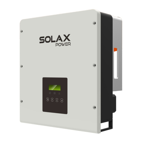
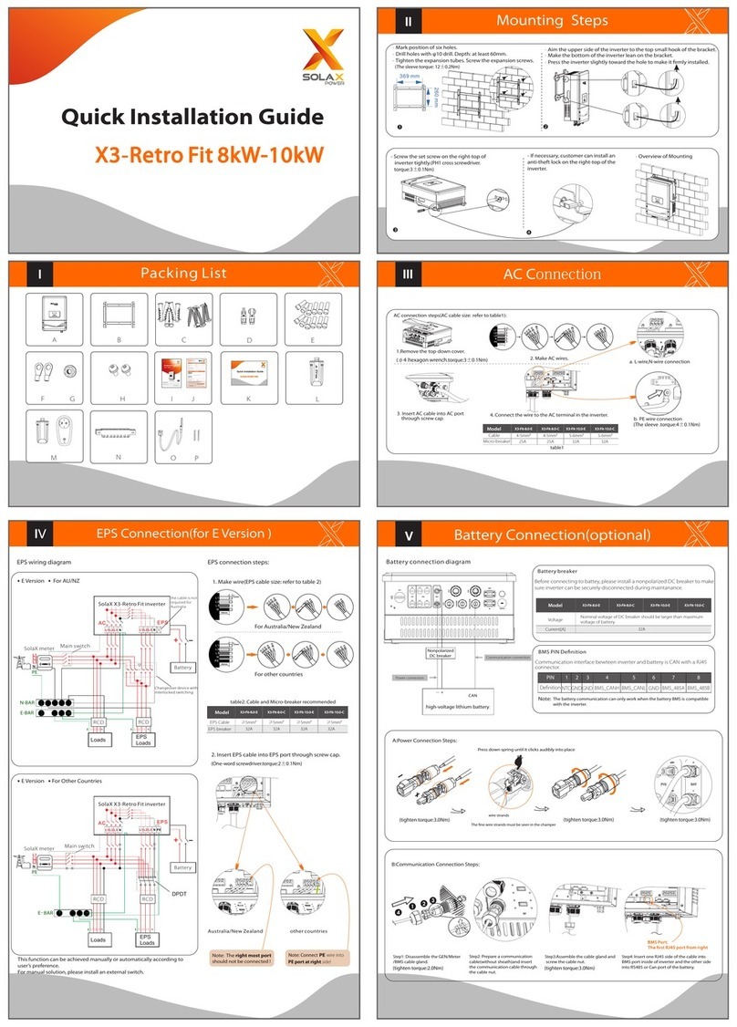
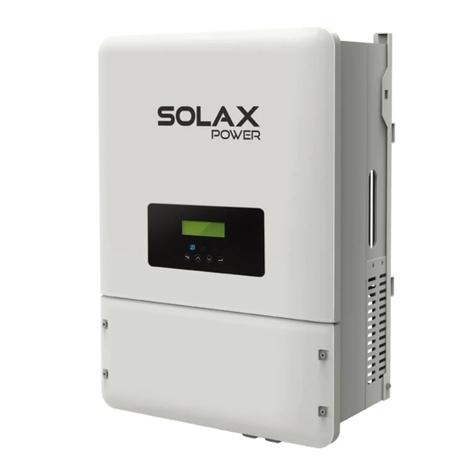
SK-TL Installation
614.00240.03
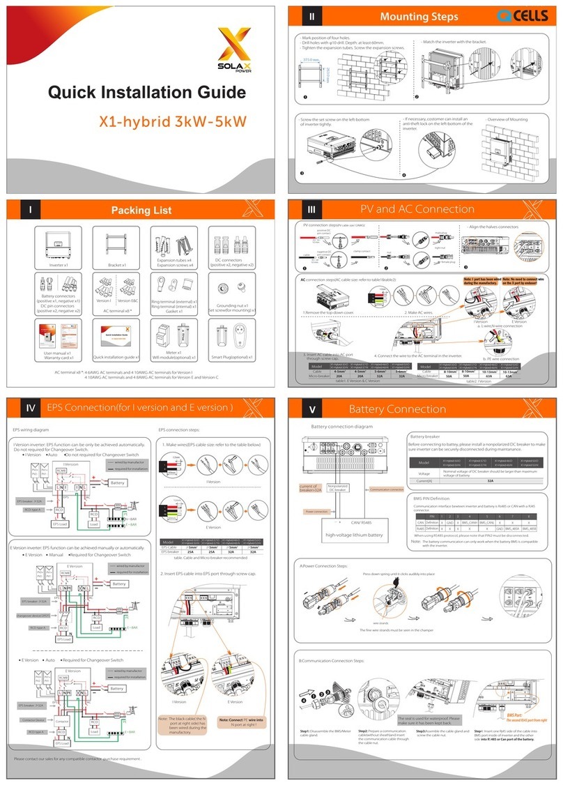
GRID/EPS LOAD/PV Connection
EPS Load connection steps (EPS Load cable size: 4~5mm):
2. Make EPS Load wires.
1. Insert EPS Load cable into “EPS” port.
3. Connect wires to the EPS Load circuit breaker (inside the box) and
N-bar respectively.
12mm
reserved
PV connection steps (Please use the PV special cables):
12mm
1. Insert PV+ and PV- cables into PV ports. 2. Make PV wires.
4.Connect wires to the DC
disconnect switch.
12mm
Grid connection steps (AC cable size: 4~5mm):
2. Make AC wires.
1. Insert AC cable into “GRID” port.
3. Connect wires to the Grid circuit breaker (inside the box), N-bar and
ground terminal respectively.
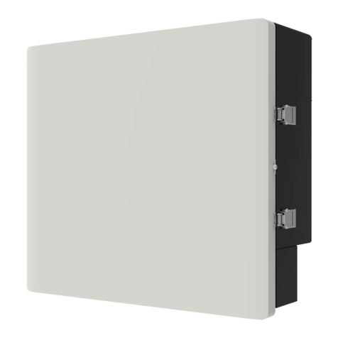
SK-TL BMU
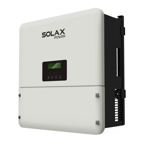
Connection between SK-TL and BMU (Wiring of SK-TL side).
- Find the BUS connectors and CAN connector that has already been inserted into the ports on the BMU.
- Insert RJ45 side of the CAN connector into “CAN” port on the SK-TL.
- Insert the BUS connectors into the “BUS” port on the SK-TL.
- Match SK-TL with the bracket.
- Install the bracket.
Connection between SK-TL and circuit breakers ( Wiring of SK-TL side).
- Find PV connectors, AC connector and EPS connector inside the box.
- Plug PV connectors to DC por ts on the SK-TL by numbers.
- Plug AC connector to “GRID” port. - Plug EPS connector to “EPS” port.
item⑥
item⑦
*Notes: Please refer to Quick Installation Guide or User Manual in SK-TL packaging for system setting.
Wi-Fi Connection
CT Installation
II
IX
- Find Wi-Fi connector and Wi-Fi antenna in Solax Box 3.0 packaging.
- Tighten the tube side of the Wi-Fi connector
with the “WIFI” port on the SK-TL clockwise.
- Tighten the screw side of the Wi-Fi
connector with Wi-Fi antenna through
the “WIFI” gland on the box.
(Make sure the hinge of the Wi-Fi antenna
is inside the box.)
item①
tube screw
item②
*Note: Please refer to Wi Setting Guide in SK-TL packaging for Wi-Fi setting.
hinge
item②
CT connection steps:
- Abbreviated drawing of the CT connection
- Find CT in SK-TL packaging.
- Cut off the RJ45 connector.
- Insert the CT wire though the “Meter” gland.
- Connect CT wire to a RJ45 connector.
- Please follow the sequence below:
Pin
1
CT
Red wire
2 3 4 5
X
76
X
8
X X X X Green wire
L
- Hang the CT on the Live line which
connects to the electric meter
(Arrow towards the public grid).
- Insert RJ45 to “CT” port on the SK-TL.
LOAD GRID
Home
Electric
Meter
Meter Box
Main
Switch
Battery Inverter
Main Switch
Pv1+
Pv1-
Pv2+
Pv2-
3.Pass the wires through the
corrugated tubing.
item⑩
Wiring Diagram
Pictorial Wiring Display
Ground
N-Bar
System Power On/Off Procedure
X
DC Disconnect Switch & Circuit Breakers
(Outside the box):
Circuit Breakers (Inside the box):
EPS Load
breaker-IN
Grid breaker-IN
EPS GRID Reserved
Step 7: Switch on AC “Main Switch (Battery Inverter & EPS Supply)”
located in the Meter box.
Step 6: Switch on Grid & EPS Load
& cooling circuit breakers.
Battery1 breaker Battery2 breaker
Grid breaker EPS Load
breaker
Battery1 breaker Battery2 breaker
Grid breaker EPS Load
breaker
Step 5: Switch off LG-Battery switch.
Step 6: Switch off Inverter switch.
Step 7: Switch off Grid & EPS load
circuit breakers inside the box.
PV system restart procedures: PV system shutdown procedures:
Step 1: Switch on Grid & EPS load
circuit breakers inside the box.
Step 4: Switch on DC disconnect switch.
Step 2: Switch on LG-Battery switch.
Step 3: Switch on Inverter switch.
Step 5: Switch on Battery1 & 2
circuit breakers.
Step 4: Switch off DC disconnect switch.
Step 3: Switch off Battery1 & 2
circuit breakers.
Step 1: Follow the “Battery Shutdown Procedure” to turn off the AC
“Main Switch (Battery Inverter & EPS Supply)” located at the Switchboard.
Step 2: Switch off Grid & EPS Load
& cooling circuit breakers.
EPS Load
breaker-IN
Grid breaker-IN
EPS Load
breaker-IN
Grid breaker-IN
DC disconnect switch
DC SWITCH
ON
OFF
GRID Battery1
EPS FAN Battery2
Circuit Breakers outside the Box
System wiring diagram:
Items highlighted in grey should be performed inside the box.
GRID EPS PV1 PV2
ON
OFF
METER WIFI
LAN
GRID Battery1
EPSFAN Battery2
*Notes: The system wiring diagram does not include the cooling circuit. The cooling circuit has
already been connected upon delivery.
The cooling circuit will run automatically when the ambient tempreture of the box is
over 45℃.
SK-TL
BMU
BUS
CAN
BMS
TEMP
BAT
+
-
+
-
EPS Contacter
N-BAR
Grid
breaker
-IN
Grid
breaker
EPS Load breaker
EPS Load
breaker-IN
ON
OFF
ON
OFF
*Notes: The alarm light will emit red when the inverter is faulty.
