Contents
1 Safety Information ......................................................................................................................................................................................................1
1.1
Symbols.........................................................................................................................................................................................................................1
1.2
Safety Instructions....................................................................................................................................................................................................2
1.2.1
General Safety Precautions......................................................................................................................................... 2
1.2.2
Battery Handling guide............................................................................................................................................... 2
1.2.3
Response to Emergency Situations............................................................................................................................. 3
1.3
Qualified Personnel..................................................................................................................................................................................................3
2 Product Introduction .................................................................................................................................................................................................4
2.1
General Information ................................................................................................................................................................................................4
2.2
Product Features.......................................................................................................................................................................................................4
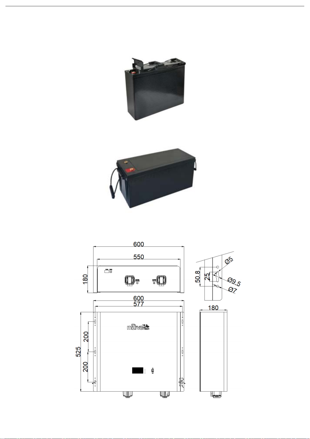
2.3
Appernce and Mechanical Drawing ..................................................................................................................................................................5
2.4
Electrical Performance ...........................................................................................................................................................................................7
2.4.1
Battery Pack Parameters ...................................................................................................................................................................................7
2.4.2
BMS and Display....................................................................................................................................................................................................7
2.4.3
Bluetooth & App Function.................................................................................................................................................................................9
2.5
Transportation and Storage .................................................................................................................................................................................9
2.5.1Transportation .......................................................................................................................................................................................................9
2.5.2 Storage......................................................................................................................................................................................................................9
3 Installation .................................................................................................................................................................................................................. 10
3.1
Install Location........................................................................................................................................................................................................ 10
3.2
Tools/Safety Gears Required............................................................................................................................................................................ 10
3.2.1Tools ........................................................................................................................................................................................................................ 10
3.2.2Safety Gears For Personal Protection........................................................................................................................................................ 10
3.3
DC Cable Prepared................................................................................................................................................................................................. 11
3.3.1Choose DC Cable ................................................................................................................................................................................................. 11
3.3.2Fabrication of DC Cable ................................................................................................................................................................................... 11
3.4
Battery Pack Installation .................................................................................................................................................................................... 13
3.4.1Battery Installation............................................................................................................................................................................................ 13
3.4.2Battery Parallel Installation Guide..........................................................................................................................................................................15
3.4.3System Installation Guide............................................................................................................................................................................................15
4 Commissioning and operation ........................................................................................................................................................................................16
4.1
Operating Conditions ........................................................................................................................................................................................... 16
4.2
Battery Commissioning Steps........................................................................................................................................................................... 16
4.3
Communication Protocol Setting .................................................................................................................................................................... 17
4.3.1Setting By Battery LCD..................................................................................................................................................................................... 17
4.3.2Setting By BMS Host Software(PC)............................................................................................................................................................. 18
4.4
Communication with INVERTER or MPPT................................................................................................................................................. 20
4.4.1Master/RS485/CAN Ports Introduction .................................................................................................................................................. 20
4.4.2Dial switch setting ............................................................................................................................................................................................. 21
5 Troubleshooting........................................................................................................................................................................................................ 21
6 Liability Limitation .................................................................................................................................................................................................. 22