Soldron 385D Technical manual

Operation instruction
LEAD-FREE SOLDERING STATION
Model:385D
Thank you for purchasing LEAD-FREE SOLDERING STATION.
Please read this manual before use, and keep
it after reading it for future reference.
Applicable product model: 385D

This product is a fully automatic tin output device, you can choose one-hand
operation, foot pedal tin feeding operation; flexible tin output, fixed metal pipe
output tin multiple ways; efficient, simple and easy welding. The stepper motor
is controlled by the instruction of the single-chip microcomputer, and the tin
WARN
The definitions of "Warning" and "Caution" in this manual are as follows:
WARNING: Misuse can result in death or serious injury to the user.
ATTENTION: Abuse may result in injury to the user or substantial damage to
the objects involved. NOTICE
● when the power is turned on, the temperature of the soldering iron tip
is in a high temperature state.
● Since abuse may result in burns or fire, please strictly observe the following:
● Do not touch the metal parts near the tip of the soldering iron.
● Do not use the soldering iron tip near flammable objects.
● Notify other people in the factory that the tip of the soldering iron is very
easy to burn and may cause a dangerous accident. Power should be turned
off during breaks or after work.
● When replacing parts or installing the tip, turn off the power and allow
the tip to cool to room temperature.
● In order to avoid damage to the welding station and maintain a safe working
environment, the following items should be observed:
● This product uses a three-wire grounding plug, which must be inserted into
a three-hole grounding socket. Do not change the plug or use an ungrounded
three-prong adapter to make a poor ground. For extension cords, use a grounded
three-wire power cord.
● Do not use a soldering iron tip for work other than soldering.
● Do not knock the soldering station against the worktable to remove
the flux residue, which may seriously damage the heating core.
● Do not modify the welding station without authorization.
● When replacing parts, the original parts should be used.
● Do not get the soldering station wet, or use the soldering station with wet hands.
● Smoke will be emitted during welding, and the work should have good ventilation
facilities.
● When using the soldering station, do not do anything that may injure the body or
damage objects.
Product overview
1

2
Welding station
Soldering Iron handle
Product structure and components
Model
Power
Input voltage:
Temperature range:
Maximum ambient temperature:
Temperature stability:
Shell material ferro:
Tin wire diameter:
Appearance volume:
Weight:
385
60W
AC 220V +/- 10% 50Hz/60Hz
200-480°C
40°C
+2°C (still air, no load)
alloy paint
0.6-1.2MM
Length 200mm, width 140mm, height 130mm
2.5KG
Soldering iron tip to ground resistance:
Soldering iron tip to ground potential:
Heating element:
Wire device:
Length ( without wies ):
Weight:
Less than 2ohms
Less than 2 mV
Ceramic
1.2 meters
190mm
123 grams (including tin conduit)
1.Tin Spool
2.Out of the box
3.Out of the tin tube
locking screw one
4.Wire diameter ajustment Screw
5.Display window of tin
output parameters
6.Button for parameters of tin output
7.Catheter
8.Handle
9. Stand
10. Pressure adjustment screw
11. Clutch lever
12. Heating indicator light
13. Temperature adjustment knob
Figure (1) Whole machine (Type B)
output is precisely and flexibly controlled. The length, speed and amount of tin
returning can be adjusted. All parameters are digitally displayed, which is clear
at a glance. The welding effect of the product is stable, the work efficiency is
significantly improved, and the combined structure is optimized. The heating
element of the soldering iron is imported low-voltage ceramic heating element,
which is fast and stable in heating, safe and reliable.

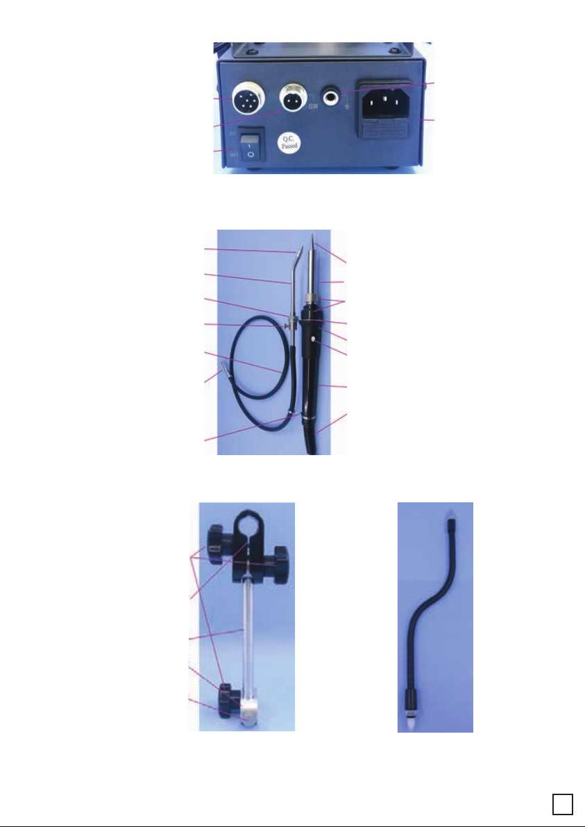
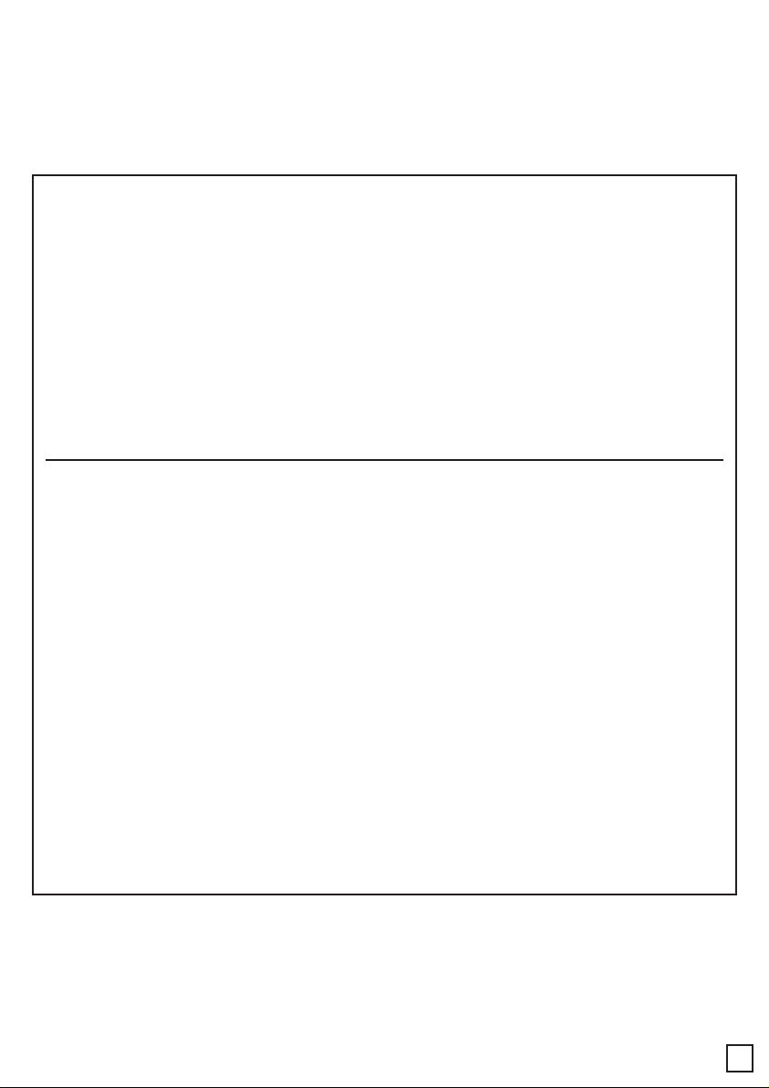
Figure (2) Rear panel
14. Handle interface
15. Foot pedal interface
16.Power switch
17.Ground
18.Power
8.Soldering iron tip
9. Stainless Steel Sheath
10. Socket + Nut
11. Connect mesons
12. Handle sheath
13. Out tin button
14. Handle tube
15. Handle wire and sheath
(c-type handle has this equipment)
2. Stainless steel guide tube
3. Lock nut
4. Catheter set screw
5.(B type ) tin tube
6. Outlet tin pipe joint
7.Locating ring
1. Out of the tin nozzle
1.Hand nut
2. Handle clip
3. Stand rod
4. Fix the cluminum cake
5.Aluminum pie screw
Figure (3) Handle assembly
Figure (4) Bracket Figure (5) Optional universal metal hose
(Type A)
3

Set up and use the soldering station
A. Solder stand and solder wire installation
Note: Before installing and electrifying, check whether the power supply
voltage is consistent with the working voltage on the nameplate of the
machine ,After the power is turned on, the heating indicator (1)-12 will light
up, and the heat pipe of the handle will heat up. Operate carefully to avoid
burns.
Select the tin wire with the appropriate wire diameter according to the solder
joint, adjust the normal pressure (10. Pressure adjustment screw), set the gap
between the transmission wheels (4. Wire diameter adjustment screw), pay
attention to the tin wire from the downward penetration into the tin hole , after
the power is turned on, the mode is set to (0), press the manual switch or pedal
until the tin wire is sent to the tin outlet, and select the tin outlet as a fixed metal
pipe and a movable tin hose according to actual needs.
1. Connect the assembly wires to the socket of the soldering station.
2. Place the soldering station on the soldering station stand.
3. Insert the plug into the power outlet. Remember to ground.
4. Press the power switch.
B. Connect the handle
Fix the handle on the bracket clip (4) or the soldering iron seat, insert the
handle into the rear panel and connect the handle as shown in Figure (2) (14.
Handle interface), and lock it tightly
C. Connect the foot switch
D. Connect the power
Calibrate Solder Station Temperature
Note: When connecting or disconnecting the soldering station, remember
to turn off the power to avoid damage to the soldering station.
Insert the plug of the foot switch into the "SW" jack on the rear panel of the
machine
Recalibrate the soldering station temperature every time the handle heating
element or the soldering iron tip is replaced.
The way to recalibrate the soldering station temperature is to use a soldering
iron tip thermometer to calibrate. This method is more accurate.
Calibration with a soldering iron tip thermometer
1) Set the temperature to 350 degrees Celsius.
2) When the temperature is stable, use a thermometer to measure the actual
temperature of the current soldering iron tip.
3) Use Phillips screws at the "CAL" hole at the bottom of the machine to adjust
the actual temperature to be consistent with the set temperature.
4

Operation panel
1. Adjustment of tin discharge: press "*" for more than 1 second, the 1-2 digits
of the adjustment parameter will flash (as shown in the figure below), enter the
setting of the length of the tin wire, and press "UP" "DOWN" to adjust the value
(this length is in non-0 mode is valid), the value is 0-99.
2. Press "*" to confirm and enter the third parameter adjustment, the adjust-
ment parameter of tin return setting flashes (as shown in the figure below), and
the value is 0-9.
Troubleshooting
Tin parameter setting
4) It is recommended to re-calibrate the temperature every time a new tip or
handle is replaced.
When the following problems occur with the welding station
1) The indicator light is on, but the heating core is damaged, replace the
handle or heating core
2) No power supply, the tin feeding indicator window is not on, check the fuse,
power cord and power socket
3) The tin force is not enough, the wire diameter gap is too large, adjust figure
(1)
4) Adjustment figure (1) 10. Pressure adjusting screw
Description: Motor Stepper Motor
Length 0-99mm
Back tin amount 0-9mm (fixed speed 40mm/S)
Interval time 0-9S
Speed 0=2mm/S, 1=8mm/S, 2=12mm/S, 3=16mm/S, 4=20mm/S, 5=24mm/S,
6=28mm/S, 7=32mm/S, 8 =36mm/S, 9=40mm/S;
Tin mode automatic (1-9)/manual (0)
5

3. Press "*" to confirm and enter the fourth parameter adjustment, enter the
interval time setting of multiple welding, the adjustment parameter flashes (as
shown in the figure below), the value is 0-9
4. Press "*" to confirm and enter the 5th parameter adjustment, enter the tin
feeding speed setting, the adjustment parameter flashes (as shown in the
figure below), and the value 0-9 valid.
5. Press " * " to confirm and enter the 6th parameter adjustment, enter the tin
feeding mode setting, the adjustment parameter flashes (as shown in the figure
below), the value 0-9 is valid, 0: jog, 1-9 automatic tin output times.
6. Press "*" to confirm and exit. After all parameters are adjusted and stored in
the chip memory, you can to use.
When manual work is started (in 0 mode), The length is shown in the figure
below. In automatic mode, the length will display the length of the tin to be sent
in real time.
LENGTH
1. A soldering iron tip with the largest contact area between the soldering iron
tip and the solder joint should be selected. The largest contact area can
produce the most effective heat transfer, so that the operator can quickly
solder high-quality solder joints.
Choose the right soldering iron tip to meet the welding requirements
6

2. A soldering iron tip that has a good path to transmit heat to the solder joints
should be selected. A soldering iron tip with a shorter length can be controlled
more precisely. For the soldering of densely assembled circuit boards, a longer
or angled soldering iron tip may be selected.
1. After the temperature is stable, clean the soldering iron tip with a cleaning
sponge and check the condition of the soldering iron tip.
2. If the tin-plated part of the soldering iron tip contains black oxide, a new tin
layer can be plated, and then wipe the soldering iron tip with a cleaning
sponge. This cleaning is repeated until the oxide is completely removed, and
then a new layer of tin is applied. Scrub the tip on a dry or dirty sponge or cloth
(a clean, moist industrial-grade and sulfur-containing sponge should be used).
● Soldering iron tip temperature If the temperature is too high, it will shorten
the life of the soldering iron tip, so you should choose the lowest possible
temperature.
temperature. At this time, the temperature of the soldering iron tip has recov-
ered well, and the appropriate temperature can Soldering is sufficient, and it
also protects temperature-sensitive components.
● Cleaning
The tip of the soldering iron should be cleaned regularly with a cleaning
sponge. After soldering, the soldering iron Residual flux-derived oxides and
carbides in the head damage the solder iron tip, causing welding errors, or
reducing the thermal conductivity of the soldering iron tip retreat. When using
the soldering station continuously for a long time, the soldering station should
be disassembled once a week ,The iron tip removes oxides to
prevent damage to the tip and reduce the temperature.
● When not in use
When the soldering station is not in use, do not allow the soldering station to
be in a high temperature state for a long time.It will convert the flux on the
soldering iron tip into oxides, causing the soldering iron tip,The thermal
conductivity is greatly reduced.
● After use
After use, the tip of the soldering iron should be wiped clean, and a new layer
of tin should be applied to prevent the soldering station Head causes oxidation.
Use of soldering iron tips
Maintenance of soldering iron tips
● Inspect and clean the tip of the soldering iron
The solder or iron plating is impure, or the soldering surface is not clean
1. Remove the tip from the soldering station handle after the tip has cooled.
2. Use 80# polyurethane grinding foam to set the temperature to 250 degrees
Celsius.
7

● Note: Proper daily maintenance will effectively prevent the soldering
iron tip from not getting tin.
Schedule 1
List of packing accessories:
Power cord*1 piece
Manual*1 book
Handle 385B*1 stick
Tin spool*1 piece
Bracket *1 set
Foot pedal *1 pay
Hexagonal *1 piece
key *1 piece
Schedule 2
Commonly used 900M series
soldering iron tip selection 900M-I 0.2I
900M-B 0.5B 1B 2B
900M-C 1C 2C 3C 4C 5C
Cross from the tin tube*1 set
3. Use a foam block or 100# emery paper to remove the dirt and oxides on the
tinned surface of the soldering iron tip.
4. Put the soldering iron tip into the handle, wrap the newly exposed soldering
iron tip with tin wire (above Φ0.8mm) containing rosin, and turn on the power
of the soldering station.
1. Immerse the solder with fresh solder after each use, which can prevent the
oxidation of the iron tip and prolong the life.
2. Try to use a lower temperature when it can work. Low temperature can
reduce the oxidation of the soldering iron tip.
3. Use a thin tip only when necessary, the coating on a thin tip is not as dura-
ble as the coating on a blunt tip.
4. Do not use a soldering iron tip as a probing tool. Bending the soldering iron
tip will crack the coating and shorten the service life.
5. Try to use less active rosin flux, because high content of active rosin will
accelerate the corrosion of the iron tip coating.
6. Turn off the power as much as possible without using the soldering iron to
prolong the life.
7. Do not apply heavy pressure to the soldering iron tip, because greater
pressure does not equal fast heat transfer. In order to improve heat transfer,
the solder must be melted to form a thermally conductive solder bridge
between the soldering iron tip and the solder joint.
8

Schedule 3
Optional accessories
385C with manual switch handle
Advanced Aluminum Alloy Soldering Iron Stand
Universal metal tin hose (type A)
900M-D 1.2D 1.6D 2.4D 3.2D
900M-K SK K LK
9
Table of contents
Other Soldron Soldering Gun manuals