Solex GAG-08DC User manual

- 1-
DC INVERTER
AIR TO WATER HEAT PUMP
User Manual
Model: GAG-08DC/12DC/16DC

- 2-
Contents list
1 GENERAL……………………………………………………………………………………………..……….3
2 SYSTEM DESCRIPTION……………………………………………………………...………..……………3
3 INSTALLATION………………………………………………………………………………………………...3
3.1 General points for installation engineer………………………………………………………………...3
3.1-1 Transport and storage………………………………………………..........................................3
3.1-2 Inspection of the installation…………………………………………........................................4
3.1-3 Sitting the heat pump…………………………………………………........................................4
3.1-4 Controller………………………………………………………………........................................5
3.2 Installation design…………………………………………………………………………………………5
3.3 Pipe Connection…………………………………………………………………………………………..8
3.4 Electrical Connection……………………………………………………………………………………..9
3.4.1 Installation Drawing…………………………………………………………………………….…11
3.4.2 Important: You need to install a separate circuit breaker in all installations………….….….11
3.4.3 Anti-freeze Function………..………………………….……………………………………….....11
3.5 Commissioning………..…………..………..………..………..………………………………..............11
3.5.1 Preparations…………………..………..………..…………………………….……………….….11
3.5.2 Inspection before Start up………..………..………..………..……………………...........….…12
3.5.3 Start up and Commissioning………...………..………..……………………............…………12
4 CONTROLLER MANUAL……..………...…………..………..……….………..…………………….…….12
4.1 Electric Parts Control Program working theory………..……..………..…………...........………….12
4.2 Operating Mode Principle………………………………………………………………………………13
4.3 Wire controller……………………………………………………………………………………………14
4.3.1 Controller……………………………………………………………………………..…………....14
4.3.2 Buttons definition………………………………………………………………………………….15
4.4 keys operation………………………………………………………………………………………...…15
4.4.1 Unlock screen……………………………………………………………………………...…...…15
4.4.2 Turn on/off………………………………………………………………………………...…..…...15
4.4.3 Change mode (5 modes) ………………………………………………………………….…….15
4.4.4 Modify the setting parameters…………………………………………………………………...15
4.4.5 Clock setting………………………………………………………………………..………..…....16
4.4.6 Timer setting……………………………………………………………………............…………16
4.4.7 Night mode…………………………………………………………………………………………18
4.4.8 Auto heat curve…………………………………………………………………………….......…18
4.4.9 Communication with LCD controller…………………………………………………………….18
4.5 System Protection and Error Codes……………………………………………………………….….18
4.6 System Adjustable Parameter Table………………………………………………………………..…20
4.7 Parameter check (Only checkable parameter list) ………………………………………………..…22
5 TECHNICALSPECIFICATION………………………………………………………………………...……24
5.1 Internal View…………………………………………………………………………………………..…24
5.2 System Drawing…………………………………………………………………………………………27
5.3 Dimensions(mm) ………………………………………………………………………………….........27
5.4 Specification…………………………………………………………………………………..…………29
6 Maintenance……………………………………………………………………………………………..……30
6.1 Maintenance and Cleaning for User……………………………………………………………...……30
7 How To Get The Most Out Of Your Heat Pump……………………………………………………………30
- 3-
1 GENERAL
The unit is an air source heat pump for space heating and sanitary water heater for houses,
apartment blocks and small industrial premises. Outdoor air is used as a heat source creating free
energy to heat your home.
2 SYSTEM DESCRIPTION
The unit is a monoblock (single unit) air/water heat pump, specially designed for the colder climate.
There is no need for bore holes and usually the system can be installed within 1 day.
The unit can both heat hot water effectively at high outdoor temperatures and give a high output to
the heating system at low outdoor temperatures. If the outdoor temperature drops to a level lower
than minus 0°C (factory setting), the auxiliary heater switches on to ensure the heat pump unit
works normally. The unit is also capable of cooling in the summer. The heat pump controller is an
intelligent wired system.
The unit is rated as 8KW/12KW/16KW. The Material/components are chosen to provide a long
service life and to fully withstand harsh outdoor conditions.
The unit has two different installation options:
1). Space heating/cooling + DHW (Domestic hot water)
2). Space heating/cooling only or DHW only
3 INSTALLATION
3.1 General points for installation engineer
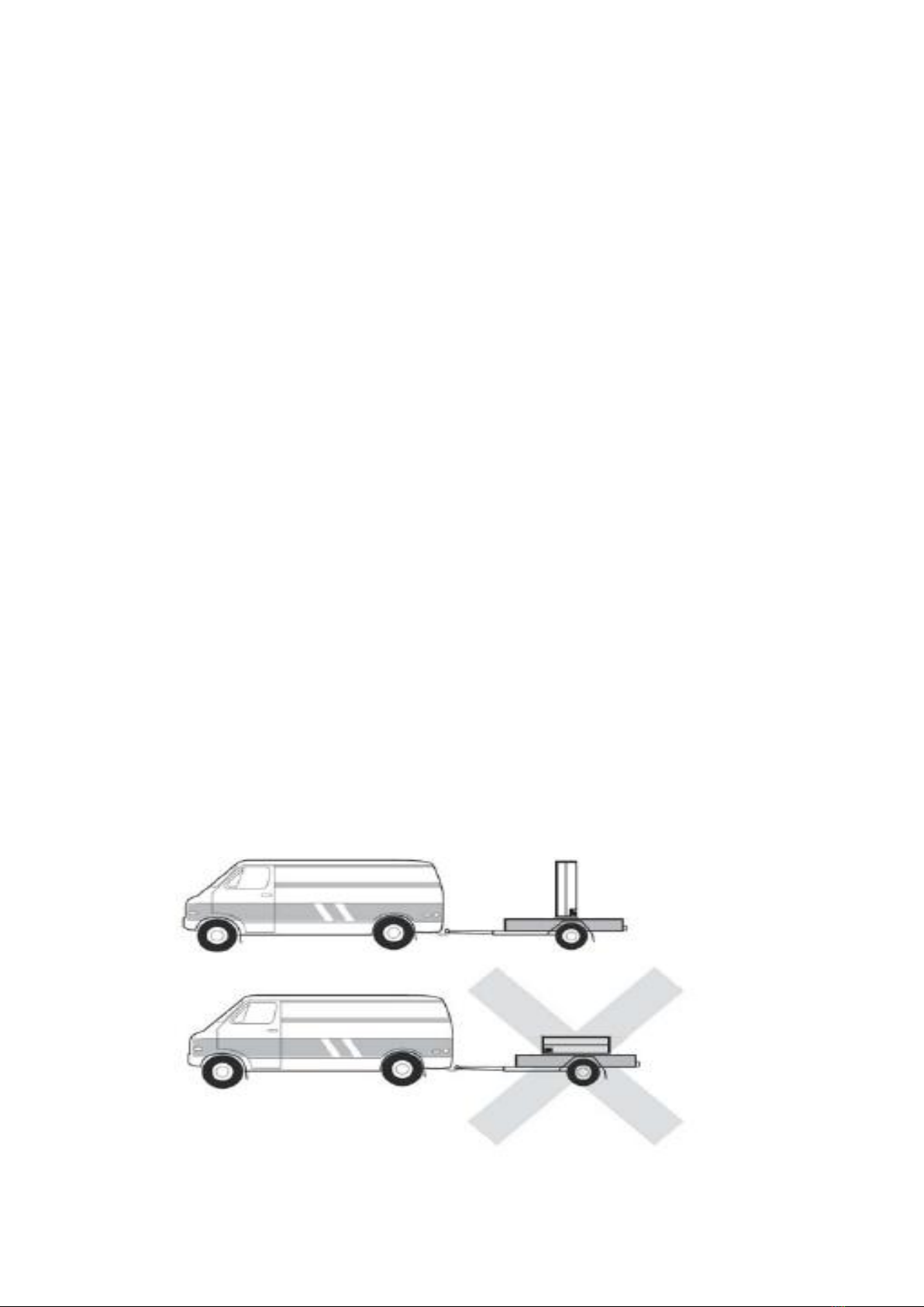
3.1-1 Transport and storage
The unit should be transported and stored vertically.
- 4-
3.1-2 Inspection of the installation
Current regulations require the heating installation to be inspected before it is commissioned .
The inspection must be carried out by a suitably qualified person and should be documented. If the
heat pump is replaced, the installation must be inspected again. In the event of installation with
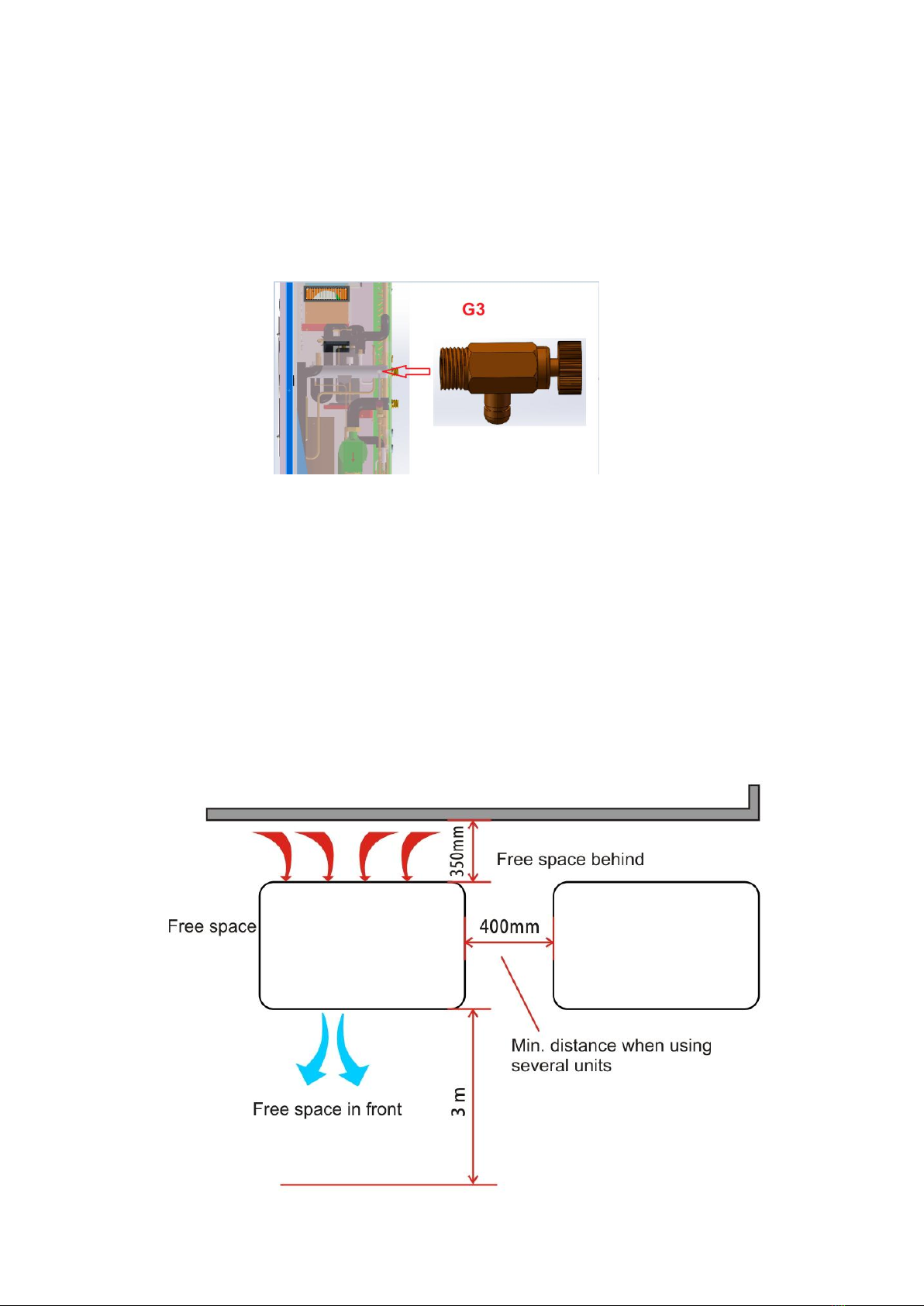
unvented (closed) heating systems, G3 unvented guidelines must be
followed during the install. It should be noted that the heat pump provides the first measure of
defense against high pressure/temperatures. A further 2 must be installed to comply with the G3
unvented procedures.
3.1-3 Sitting the heat pump
The unit is placed (securely fixed) outdoors on a firm base, preferably a concrete foundation. It
should not be positioned next to sensitive walls, for example, next to a bedroom. Also ensure that
the placement does not inconvenience any neighbors’.
Large amounts of condensation water as well as de-icing water from defrosting can be produced.
You must provide good drainage at the installation area and make sure the water cannot run out
onto paths or the like during periods that ice can form. Ideally, condensation water is led off to a
water drain or a suitable soak away. The distance between the unit and the exterior wall must be at
least 350 mm. The free space above must be at least one meter. The unit must not be placed in a
position so that air can re-circulate thus lowering the COP.
Care must be exercised so that the heat pump is not scratched during installation.

- 5-
3.1-4 Controller
The unit is equipped with an external electronic controller that handles all functions necessary for
heat pump operations. Defrosting, stop at max/min temperature, connection of the compressor
heater as well as enabling the aux electrical heater, monitoring of motor protection and pressure
switches are all controlled.
The number of starts and the operating time can also be read.
The controller is set during installation and can be used during a service.
Under normal operating conditions the home owner does not need to have access to the controller.
The unit has an integrated electronic outlet water temperature sensor that limits the outlet
temperature up to 60°C.
3.2 Installation design
The unit can be installed in several different ways.
The safety equipment must be installed in accordance with current regulations for all installation
options.
When connecting with the unit, the total water volume in the heat pump pipe system and buffer
tank must be at least 10 liters per KW of output.
A) Space Heating/Cooling + DHW
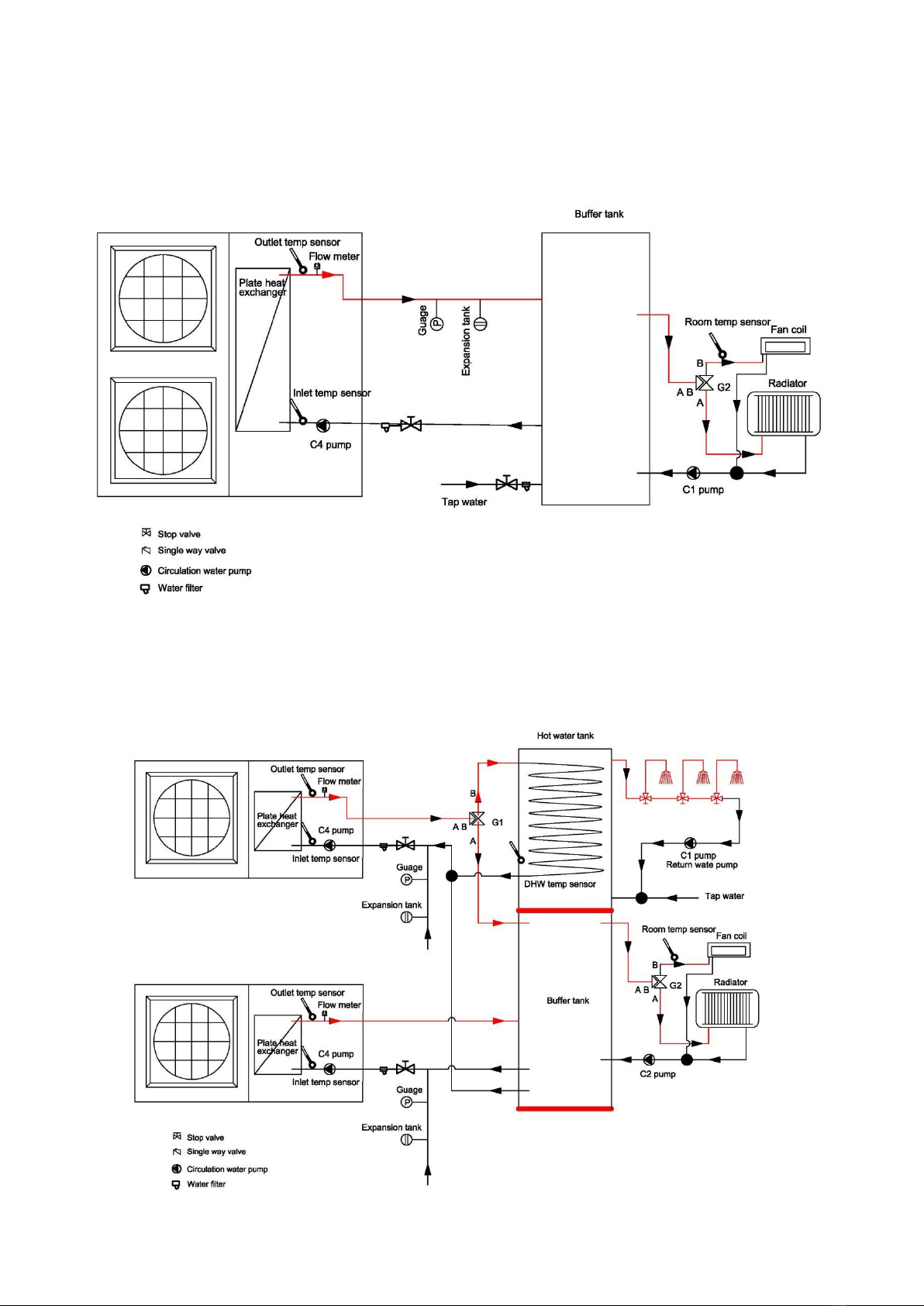
- 6-
B) Space Heating/Cooling Mode Only
C) 2x8/12/16 Installation. Space Heating/Cooling + DHW

- 7-
D)3x8/12/16 Installation. Space Heating/Cooling + DHW.
Solar Application 1

- 8-
Solar Application 2
3.3 Pipe Connection
28mm pipe is recommended.
The pipe work must be flushed before the heat pump is connected, so that any contaminants do
not damage the components parts.
The heating/cooling water inlet and outlet direction must be connected according to the marked
areas on the heat pump.
All outdoor pipes must be thermally insulated with at least 19 mm thick pipe insulation. The
insulation must also be vapor resistant.
The water circulation pump must at all times be operational (even if unit is not running) to prevent
any possible damage due to freezing. Even when in standby mode, the circulation pump is
controlled directly from the unit, which takes the outdoor temperature and temperature in pipe into
consideration to decide whether to circulate water within the system.
Shut-off valves and drain valves are fitted so that unit can be emptied in the event of prolonged
power failures.
The supplied flexible hoses act as vibration dampers. The flexible hoses are fitted so a slight bend
is created, thus acting as vibration dampening.
Important: Even though the unit has anti-freeze protection, if the circulation pump fails or there is
a problem with the power supply, there is still a risk of damage due to freezing. During the
installation Anti-freeze (Ethylene Glycol) is strongly recommended. If the air
temp is ever lower than 0c, it must use enough glycol.
- 9-
3.4 Electrical Connection
Electrical installation and service must be carried out under the supervision of a qualified
electrician. Electrical installation and wiring must be carried out in accordance with the stipulations
in force.
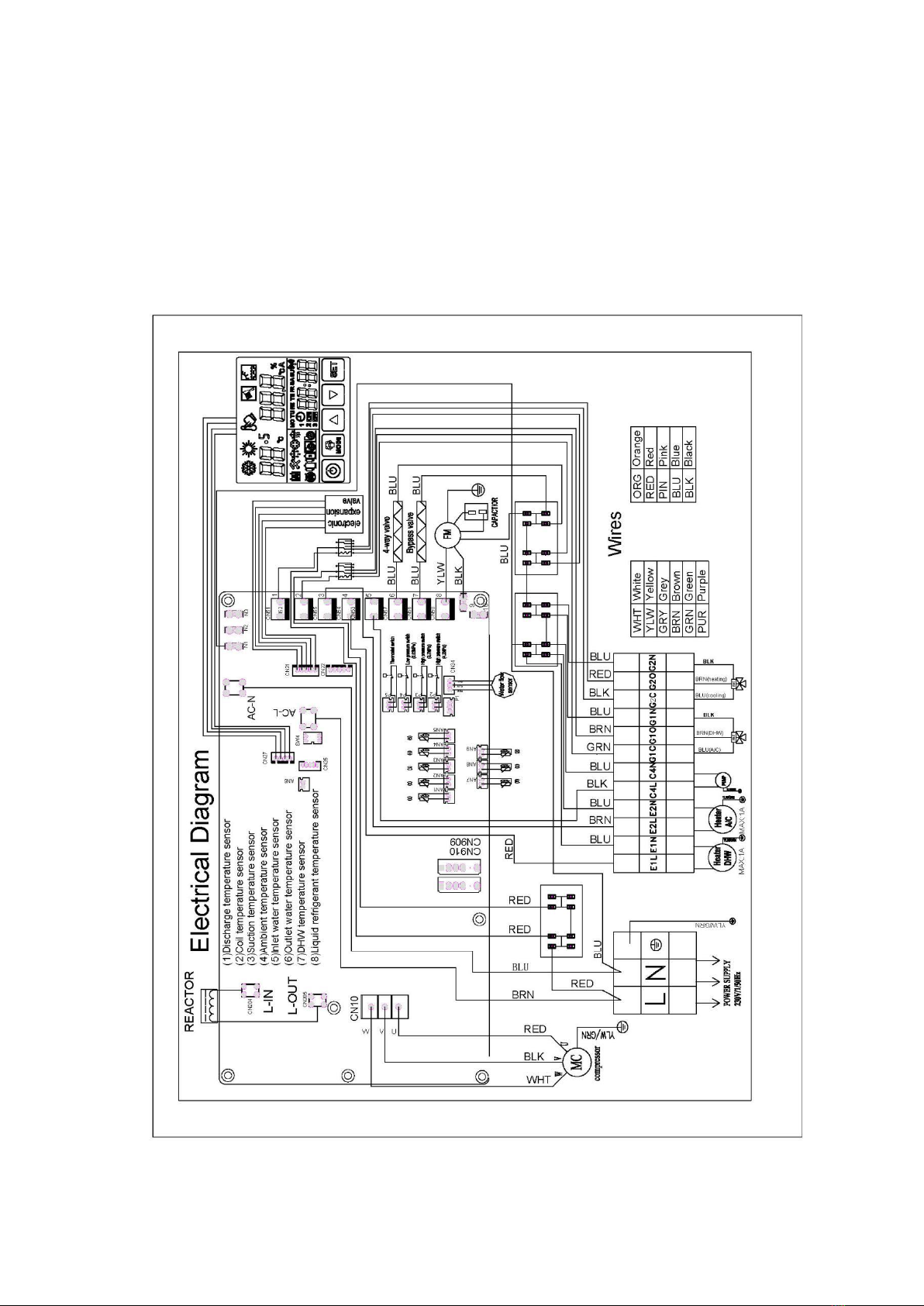
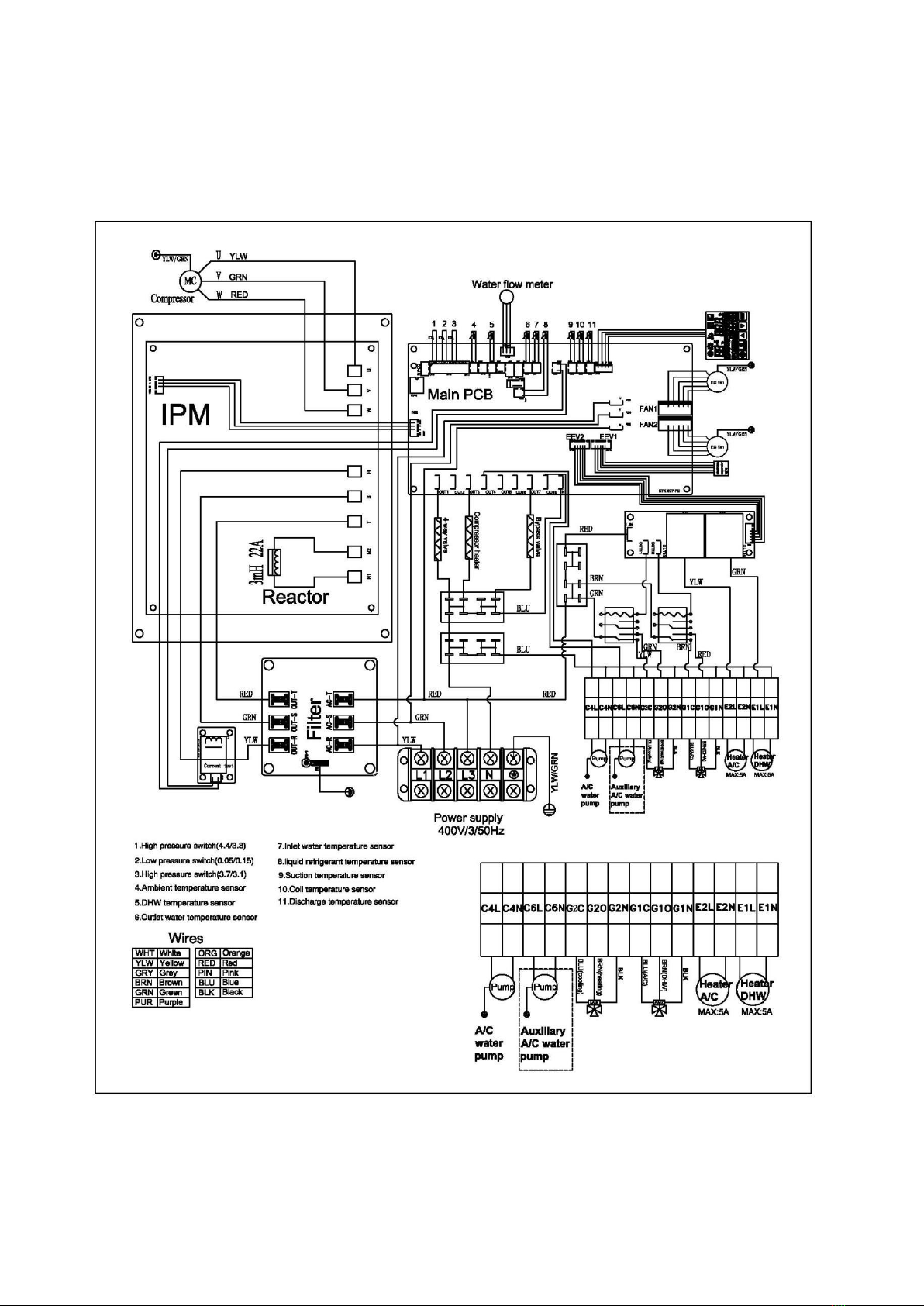
Wiring Diagram GAG-08DC/12DC
- 10-
Wiring Diagram:GAG-16DC

- 11-
3.4-1 Installation Drawing
3.4-2 Important: You need to install a separate circuit breaker in all installations.
3.4-3 Anti-freeze Function
DHW anti-freeze
When DHW water tank(AN8) temperature ≤ 4°C, system starts hot water antifreeze, start domestic hot
water mode and compressor, When hot water temperature is 12°C or higher, withdraw DHW antifreeze. If
the compressor starts over 30 minutes, withdraw DHW antifreeze.
AC anti-freeze
Air conditioning inlet (AN5) or outlet (AN7) water temperature is 4°C or lower, system starts AC antifreeze,
water pump C1 start。
When the input water temperature ≥ 12°C or compressor operates over 30 minutes , withdraw AC
antifreeze.
3.5 Commissioning
3.5.1 Preparations
Before commissioning, make sure compressor heater has already pre-heated for 3-10 minutes.
1) Compressor Heater
As mentioned above, if the temperature is lower than 10°C, it is important that the compressor heater can
heat the compressor before the first start up. In order to ensure this happens, please follow the
instructions below:
a. Disconnect the power connection of compressor, aux electric heater, circulation pump. (Due to
anti-freeze protection, the compressor, aux electric heater and circulation pump could start in
stand-by status.
b. Switch on the outside Isolator and power connection of the unit.
c. After 3-10 minutes, switch off the outside Isolator and re-connect the power connection of compressor,
aux electric heater and circulation pump.
2) Filling and Venting
Fill the system slowly ensuring bleed valves are open (if not automatic).

- 12-
3.5.2 Inspection before Start up
1) Mechanical Inspection:
a. Check the cabinet and inside pipe system for possible damage during transportation.
b. Check that the heating water circuit is filled and well vented. Check the pipe system for leaks.
c. Check the Fan making sure it can move freely.
2) Electric System Inspection
a. Check the power supply (voltage/frequency) matches the rating label and specification.
b. Check all the electrical connections for loose or damaged wires due to transportation.
3) Pipe Inspection
a. Check all the valves, and water flow directions.
b. Check for any possible leaks inside or outside of unit.
c. Check the insulation of all the pipes.
3.5.3 Start up and Commissioning
a. After the system inspection is finished, startup can begin.
b. Connect the power supply; switch on the isolator to turn on the heat pump.
c. The circulation pumps starts immediately. After 30 seconds, the fan motor starts. After another 10
seconds, compressor starts.
d. Air is initially released from the hot water and venting may be necessary. If bubbling sounds can be
heard from the heat pump, the circulation pump or radiators the entire system will require further venting.
When the system is stable (correct pressure and all air eliminated) the automatic heating control system
can be set as required.
e. Check heating water inlet/outlet temperature difference after the system is stable.
f. Check the compressor exhaust and suction temperature.
g. Adjust the parameters according to different weather conditions and user requirements.
4 CONTROLLER MANUAL
4.1 Electric Parts Control Program working theory
a) Compressor
After the compressor is shut down, it has a minimum interval of 3 minutes before the next start up
The initial "power-up" does not require the protection of three minutes;
During defrost, compress on/off interval is based on the defrost parameters.
b) Start up / Shut down Cycle
When the heat pump switches on, the water circulation pump and the fan will start 60 seconds before
compressor
When the heat pump switches off, the water circulation pump shuts down 30 seconds after the
compressor. The fan switches off 5 seconds after the compressor
During defrost, the water circulation pump does not stop running;
c) DHW Auxiliary Electric Heater E1
F08=0, E1 is not valid ; F08=1,E1 is valid.
E1 turns on as set out in the conditions below:
Ambient temperature ≤ set value (parameter F09,-20°C ~ 30°C, default 0°C);

- 13-
Compressor’s working time ≥set value (parameter F10,10 ~ 30min, default 15min);
DHW water tank temperature <setting temperature;
When DHW anti-freeze, E1 is on, when DH>15°C, E1 off.
When some error cause compressor stop, if DHW required, E1 will be on.
d) A/C Auxiliary Electric Heater E2
F05=0; E2 is not valid; F05=1,E2 is valid.
A, E2 turns on as set out in the conditions below:
The heat pump is running heating:
Ambient temperature ≤ set value (parameter F06,-20°C ~ 20°C, default 0°C);
Compressor’s working time ≥ 15minutes;
AC water inlet temperature <setting temperature;
B, When start defrost at AC heating mode, if inlet water temperature ≤39°C, E2 turns on. When Ac inlet
temp>45°C, E2 off.
C, During anti-freezing, the auxiliary electric heater E2 turns on.
D, If inlet or outlet temperature sensor breakdown, the auxiliary electric heater E2 turns on.
e) Motorized 3 way Valve G1
In DHW mode, the motorized 3 way valve is power on. In any other mode, it is power off.
4.2Operating Mode Principle
1) Space Cooling Mode
Temperature setting range is 10-25°C, the factory setting is 12°C;
2) Space Heating Mode
Temperature setting range is 10-55°C, the factory setting is 45°C;
3) Hot Water Mode
Temperature setting range is 10-60°C (50~60°C is increased by electric heater), the factory setting is
50°C;
4) Defrost Cycle
Auto Defrost mode (normal defrosting)
All heat pumps are fitted with intelligent defrost controls. A number of parameters are taken into account
before defrost begins and ends. The parameters should be set as per factory settings or otherwise set out
by an engineer. The defrost time will vary depending upon the conditions the heat pump is working in. The
length between defrosts will either extend or contract depending upon the parameters set.

- 14-
4.3 Wire controller
4.3.1 Controller
There are 5 keys for operation. Auto restart function,weekly timer.
Compresso
r1
Heating
Wifi
Anti-freeze
zeze
A/C heater
DHW temp/AC outlet
temp/parameter
value
Defrost
Cooling
DHW
Time/
Parameter
number
Timer point
Target temp setting
Mode
DHW pump
Up
Down
SET
Compressor
2
DHW
heater
A/C
pump
ON/OFF
Error
A/C inlet temp
Sterilization
Timer ON/OFF
- 15-
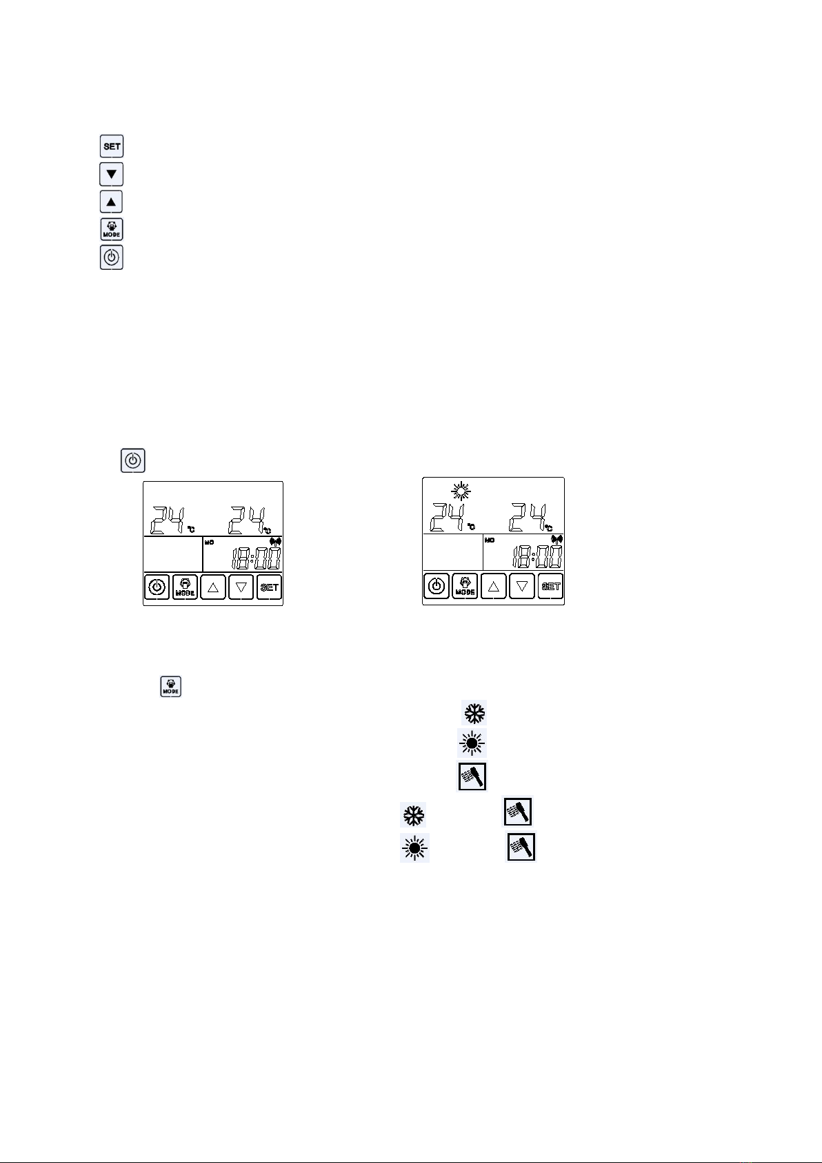
4.3.2 Buttons definition
(1) SET key: confirm the setting or check/set the parameter or manual defrost
(2) down key: reduce
(3) up key:increase
(4) mode key: change the mode or adjust time or timer setting
(5) On/Off key: Turn on or off heat pump or return the main window
4.4 keys operation
4.4.1 Unlock screen
When the screen’s light is off, the screen is locked. Touch any key, the screen is unlocked and the light on.
4.4.2 Turn on / off
Touch key.
OFF ON
4.4.3 Change mode (5 modes)
A, press the key repeatly, the mode icons will flash by recycling.
COOLING
HEATING
DHW
COOLING + DHW
HEATING + DHW
B, When selected cooling or heating plus DHW, DHW will be priority.
C, When selected DHW mode, only DHW operation, no cooling and heating.
D, Healthy sterilization is an independent automatic operation mode, if necessary, modify the parameters
individually.
4.4.4 Modify the setting parameters
A, When the selected mode is running, the unit will run in accordance with the factory set default values or
the last modification of the temperature.

- 16-
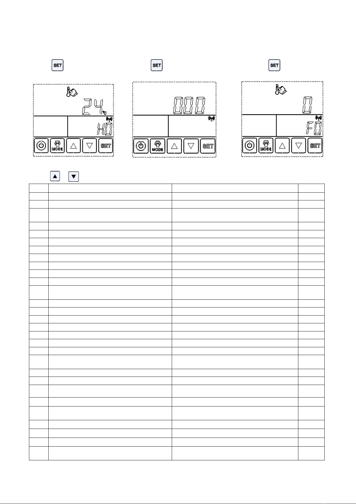
B, Set the target temperature
(1) Touch or key, the target temp setting appears.
(2) Touch key, choose the mode that you need to modify the target temperature.
Cooling mode Heating mode DHW mode
(3) Touch or key to adjust the target temperature.
C, The detailed settings in the table below
Item
Meaning
Setting range
Default
Change setting date
1
AC cooling
10°C~25°C
12°C
2
AC heating
10°C~55°C
45°C
3
Hot water
10°C~60°C
50°C
4
Antibacterial
60°C~70°C
65°C
4.4.5 Clock setting
Press key for 6 seconds, clock icon flashes :
Touch or key to adjust the time.
4.4.6 Timer setting
Press key for 6 seconds, clock icon flashes,
Press key for 6 seconds again, then ‘S’ or ‘C’appears
on the screen.
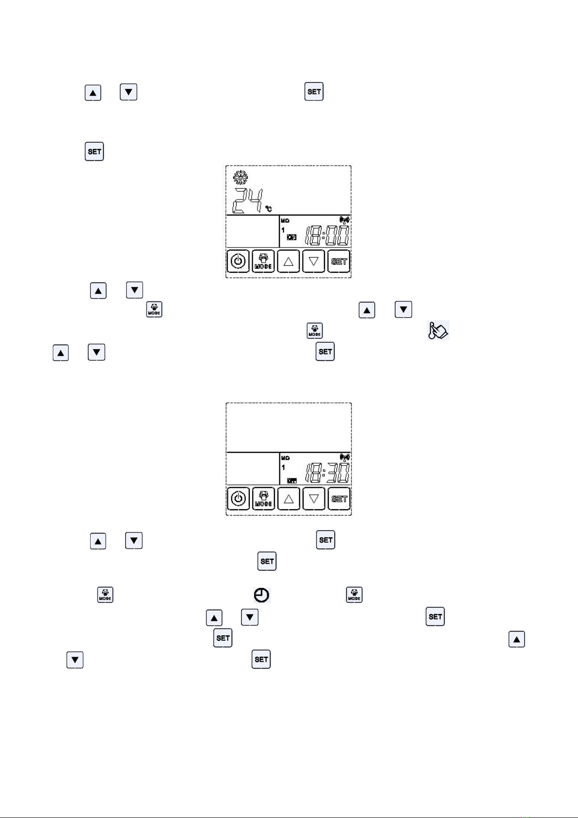
- 17-
S: once validity C:cyclic validity
Touch or key to choose ‘S’ or ‘C’, then touch to confirm, and enter to adjust time window.
A) One day can set 3 points for on.
Touch key to the day of week, then the timer No and the time data flash,
Touch or key to adjust the time of timer. Then choose the working mode and adjust the target
temperature. Touch key, ON and mode icon will flash, touch or key to choose the mode
you need. Then change the target temperature, touch key again , ON and will flash, touch
or key to change the target temperature. Touch key to confirm.
B) One day can set 3 points for on, 3 points for off .
When timer point 1 ON is finished, point 1 OFF flash.
Touch or key to adjust the time of timer, touch key to confirm.
C) If some points don’t need to be set, touch key to jump.
D) Press key for 6 seconds, clock icon flashes,Press key for 6 seconds again, then ‘S’ or
‘C’ appears on the screen. Touch or key to choose ‘S’ or ‘C’, then touch to confirm, and
enter to adjust time window. Touch key to choose the timer point that need to be cancel. Touch
or key to adjust the time to --:--, touch key, this timer point will be cancel.
- 18-
4.4.7 Night mode
(1) Night mode valid or not is up to parameter F21. If the data is set 0, means off, 1 means on. The
night mode starting time is decided by data F22. Ending time is decided by data F23.
(2) With night mode, hot water mode will run with the current setting temp +3° C, room heating run
with current setting -2°C. Room cooling run with current setting +2°C. Outdoor fan run at low
speed.
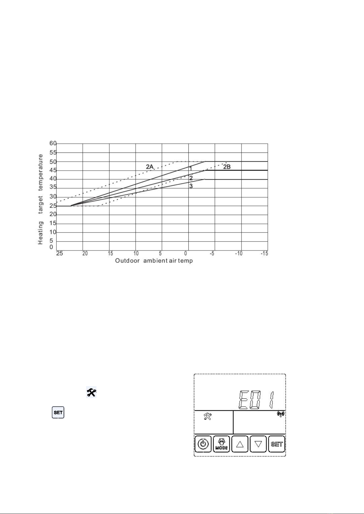
4.4.8 Auto heat curve
A. AU curve translate is decided by parameter(F14) , positive value means move up, negative value
means move down. (-15~15)
B. AC AU heat curve highest temp is decided by parameter (F13), from 30~50, default 45. When the
parameter is 45, the AU highest target temp is 45°C.
4.4.9 Communication with LCD controller
LCD controlled is connected with heat pump CN27 by 4 wires,(must in order) max 100m.
4.5 System Protection and Error Codes
If error,The Icon displays on the screen ,
touch key, the error code displays。
For example:E01

- 19-
Code
Meaning
Remark
E01/HP
High pressure switch off
1.Refrigerant volume too much 2.throtting part error
3. pressure switch fault.
E02
High pressure protection
1.Refrigerant volume too much 2.throtting part error
3. High pressure switch fault.
E03/LP
Low pressure switch off
1.Refrigerant volume too little 2.throtting part error
3. pressure switch fault.
E04
Low pressure protection
1.Refrigerant volume too little 2.throtting part error
3. Low pressure switch fault.
E06
Over current protection
Compressor current is too high
E08
High discharge temperature
protection
1.Refrigerant volume too little 2.throtting part error
3.discharge temperature sensor fault.
E09
Discharge sensor error
Temp sensor open circuit or short circuit
E10
Suction temperature sensor error
Temp sensor open circuit or short circuit
E11
Coil temperature sensor error
Temp sensor open circuit or short circuit
E12
Outdoor air temp sensor error
Outdoor air temp sensor open circuit or short circuit
E14
Inlet water temp sensor error
Temp sensor open circuit or short circuit
E15
DHW temp sensor error
Temp sensor open circuit or short circuit
E16
Outlet water temp sensor error
Temp sensor open circuit or short circuit
E17/FLO
Water flow error
1.Water flow volume too small 2. Water flow switch error
E18
Ambient temp too low
1.Outdoor air temp too low 2.temp sensor error
En
Communication error
Communication wire open or PCB error
E20
Miss/Wrong phase
Power supply error
E22
Password valid
E23
Memorizer error
PCB fault
E38
Temperature difference too high
Temperature difference between inlet and outlet water is
too high
E84
voltage protection
Voltage is too high or too low, heat pump will recover when
voltage be normal (165~265VAC)
E85
Voltage too high
Voltage≥265VAC
E86
Voltage too low
Voltage≤165 VAC
E97
DC Voltage too high
DC Voltage ≥ VDC
E98
DC Voltage too low
Voltage ≤ VDC
E99
Phase current too high
Phase current ≥ A
E100
DC motor out of step
DC motor out of step
E101/E102
Compressor Miss phase
Compressor connection line fault
E103/E103
IPM Error
IPM fault
E108
IPM temperature abnormity
IPM temperature sensor fault
E111
IPM doesn’t match compressor
IPM fault
E113/E114
PFC error
IPM fault
E116
PFC over current
IPM fault
E117
DC voltage abnormity
DC Voltage
E118
AC voltage too low
Voltage≤165 VAC
- 20-
4.6 System Adjustable Parameter Table
Press key for 6 seconds,Press key for 6 seconds again, Press key, enter the
the screen will show Hxx. then enter the password window. parameter check window.
Press or key to check different parameter.
Code
Name
Range
Default
F00
Parameter’s value return to default
0~255 : 10(return)
0
F01
Auto restart
0:off, 1:on
1
F02
Functional parameter
0: only heating 1:Cooling+heating
2: only cooling 3: DHW+(C+H)
3
F03
AC temp difference
1~30°C,minus difference
2°C
F04
DHW temp difference
1~30°C,minus difference
3°C
F05
AC auxiliary electric heater E2 validation
0: Invalid; 1:valid
0
F06
Ambient temperature to activate E2
-20~30°C
7°C
F07
The time of delayed to active E2
1~99 minutes
20
F08
DHW auxiliary electric heater E1 validation
0: Invalid; 1:valid
0
F09
Ambient temperature to activate E1
-20~30°C
7°C
F10
The time of delayed to active E1
1~99 minutes
20
F11
Water pump working mode
0(no stop),1(stop when reach temp)
2(running 1 minute every (15=F12)minutes)
F12
Water pump mode 2 interval time(F11=2)
1~99 minutes
15
F13
AC AU curve max temp value
30~50°C
45°C
F14
AC AU curve offset value
-10~10°C
0°C
F15
Auto remove error
0: no remove; 1~255minutes
30
F16
Sterilization temperature
40~80°C
65°C
F17
Sterilization interval time
0:sterilization invalid; 1~99 days
7
F18
Sterilization duration
1~99minutes
10
F21
Night mode validation (night mode: DHW
increase 3C, AC temp reduce 2C)
0:invalid; 1:valid
0
F22
Night mode starting point
0-23(time)
21
F23
Night mode ending point
0-23(time)
6
F24
Compressor and Motor speed’s output
ratio for night mode
0-100
80
F30
Defrost interval time
10~200 minutes
50
F31
Defrost time(defrost action lasting max time,will
stop defrost if longer than this value)
5~20 minutes
8
F32
Coil temp to active defrost
-30~15°C
-5°C
F33
Coil copper pipe temp to stop defrost
10~35°C
25°C
F34
Ambient temperature to active defrost
0~55°C
15°C
F35
Difference between ambient and coil temperature
to active defrost(Ambient temp lower than -7°C)
0~25°C
8°C
This manual suits for next models
2
Table of contents
Popular Inverter manuals by other brands


IPS
IPS IPS-600 Installation and user manual

IVT
IVT SW-100 user manual

GW Instek
GW Instek AFG-3021 quick start guide

Generac Power Systems
Generac Power Systems 00919-0 owner's manual

Tigo
Tigo ENERGY MODULE MAXIMIZER ES Series Installation and safety manual

Mitsubishi Electric
Mitsubishi Electric 800 Series INSTALLATION GUIDELINE


