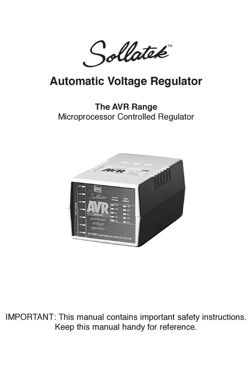
Sollatek SPCC16E User manual

SOLLATEK SPCC16E
SOLAR CHARGE CONTROLLER
Typical Solar System
Solar Charge Current 16 Amps
Load Current 16 Amps
Nominal Voltage (field selectable) 12 or 24 VDC
Current Consumption : Charging
Discharging
No Load
12 mA
12 mA
12 mA
Voltage Thresholds : Load disconnect
Load reconnect Hys.
Charge disconnect
Charge reconnect Hys.
10 - 12 V
0.5 - 1.0 V
13 - 15 V
0.5 - 2.0 V
Battery Temp. Compensation (int or ext) -3mV/°C/cell
Operating Temperature -10° to +50° C
Connections (max cable 6mm²) Screw Type
Dimensions (mm) 182x132x53
Weight (Kg) 0.4
SPCC16E Specifications
Installation Sequence
Having made any adjustments necessary for operation of the SPCC16E, follow the installation sequence below :-
1. Mount the SPCC16E on to a flat, verticle surface with the cable glands facing towards the floor. Insert one
screw into the wall upon which to hang the controller, afterwhich insert mounting screws into the two holes
at the bottom section of the SPCC16E. The controller should be as close to the battery as possible, in a
well ventilated room and away from direct sunlight.
2. Connect the load cable to the controller through the left hand cable gland. The cable should have been
stripped of 10mm of insulation and inserted into the terminals, observing the correct polarity. (Red/Brown is
normally positive ‘+’, Black/Blue is normally negative ‘-’)
3. If required, install the external battery sense cable between the battery terminals and the ‘Batt sense’
terminals in the SPCC16E. The external temperature compensation probe cable should be connected to the
terminals of the SPCC16E and the actual probe stuck onto the side of the nearest battery within the system.
4. Connect the Battery cable, observing the correct polarity. A fuse (20A) should be fitted in the battery cable
at the positive terminal of the battery to prevent accidental short circuit damage of the controller and
system.
5. Connect the cable from the solar module (s) ensuring that the solar module is covered. (During daylight
sparks may occur at the controller terminals if the module is not covered)
· Ensure that all connections and terminals are clean and tight
· Always use the largest available cross section of cable in order to prevent voltage drops. If in doubt consult
your dealer.
System Status Indication
* Solar panel is generating electricty and charging the battery
except when green ‘Battery full’ LED is illuminated.
* Battery is fully charged and the solar module has been
disconnected
* Battery is in a good state of charge.
* Battery is in a low state of charge and the load will soon be
disconnected, depending upon LVD setting
* The load output has been disconnected to avoid damaging
the battery due to excessive discharge.
* The reset switch will re-connect the load after LVD has
occured and before LVD-H in case of an emergency or the
LVD occuring at an inconvienient time. The load will dis-
connect when LVD is reached again.
Troubleshooting
MOTPMYSMOTPMYS MOTPMYS MOTPMYSMOTPMYS ESUACESUAC ESUAC ESUACESUAC NOITULOSNOITULOS NOITULOS NOITULOSNOITULOS
thgilyadgniruddetanimullitonsiDELnuS detcennocylreporptonseludoM
raloS· tahterusnednasnoitcennoceludomkcehC· tcerroceraseitiralop
etanimullitonodsDELsutatSyrettaB
nwolbe
sufrodellatsniyltcerrocniyrettaB· seirettabteW(wolyrevsidicAyrettaB· )ylno daedsiyrettaB·
stiucrictrohsrofesufdnaselbackcehC· snoitcennocytiraloptcerrocdna retawdellitsidhtiwsllecyrettabehtlliF· ecalpeR·
)pmA02
(swolbesufdaollanretnI daolehtnitiucrictrohS· tnerruchcumootgniwardsidaoL· selbackcehc,tiucrictrohsriape
rdnadniF· ezisdaolecudeR·
ehtfo)gnirettahc(noitarepoffo/nodipaR syaler
tesneebevahsdlohserhtegatloV· yltce
rrocni dezisrednuyltnacifingissiyrettaB·
nidetacidnistimilotsdlohserhttsujdA· snoitcurtsnieseht yrettabfo
yticapacrorebmunesaercnI·
etarepotonodsdaoL
esufdaolnwolB· pmalroebutdaeD:sthgiL· egatlovhgiH(llamsootsir
etemaidelbaC· )pord
)evobaees(nwolbsahesufyhwhsilbatsE· ecalperneht pmalroebutecalpeR· egatlovecuderotezis
elbacesaercnI· sessol
noitarepOmetsyStcerrocnI .yltcerrocnIteSsrepmuJ· .gnittesersdeeNmetsyS·
.faelrevoelb
atrepsasrepmuJteS· 5retfaecalperdna1Jevomer,teseroT· sdnoces
Charge controllers are one of the most
essential parts of any solar electric system,
monitoring and controlling the system and
protecting the battery against overcharge by
the solar modules and over discharge by the
loads. A Sollatek SPCC will greatly increase
battery lifetime and system reliability, whilst
also giving the user a constant display of the
system status.
Once installed, the SPCC operates
automatically and requires no attention or
maintenance from the user.
The SPCC16E is protected against short
circuit, overload, reverse current flow, reverse
polarity and lightning power surges.
Fuse
LVD Low Voltage Disconnect
LVD-H Low Voltage Disconnect
Hysteris
Hysteresis The voltage the battery
must rise by before
reconnecting again.
Reset

For Qualified personnel only
The SPCC16E is factory set at for immediate use at 12V using internal battery sense and temperature
compensation and at the voltage thresholds set for a flooded lead-acid battery (see below). In order to adjust
please follow the instructons noted below. Make sure that the SPCC16E is disconnected from the system
before attempting any adjustments.
Voltage Thresholds
The voltage thresholds can be re-set using the four rotary controls located in the upper half of the controller.
The adjustable controls allow the installer to set the voltage thresholds to their particular preference, depend-
ing upon battery type and system requirements. (for 24V double all figures)
Recommended
thresholds Flooded lead-acid
batter
y
Sealed Gel t
yp
e
batteries
LVD 11.3 11.3
LVD-H 12.3
(
1V
)
12.3
(
1V
)
HVD 14.4 14.0
HVD-H 12.8
(
1.6V
)
12.8
(
1.2V
)
Advanced Technical Modifications
!
The minature thumbwheels are removable to prevent un-authorised tampering of the rotary controls. When
replacing them, ensure they are fitted in the correct orientation.
The low and high reconnect voltages are a hysterisis of the low and high disconnect voltages. If the required
low volt disconnect is 11.5 volts and the required reconnect 12.3 volts then the LVD-H rotary control should be
set to 0.8 v (11.5 + 0.8 = 12.3). Similarly if the HVD is 14V and the required reconnect is 12.9V, the HVD-H
control should be set to 1.1V (14-1.1=12.9)
12 or 24V Operation
The SPCC16E is supplied ready for 12V operation. The installer can easily set the controller for 24V operation
by adjusting jumpers as shown in Jumper Position table opposite. All voltage figures will double.
External Battery Sense
Although the SPCC16E is fitted with internal battery voltage sensing, for greater accuracy an external sense
cable can be installed between the battery terminals and the ‘Batt sense’ terminals within the controller as
shown below. It is important to make sure that the battery sense cable polarities are correct and J1 and J2 are
set to 2+3 position. A 1Amp fuse should befitted in the positive sense wire at the battery end.
Jumper Positions
External Temperature Compensation
The SPCC16E is fitted with internal temperature compensation which will adjust the controllers operation
according to the ambient temperature, however for greater accuracy or if the batteries are located in an
enclosure or a different room then an external temperature compensation probe (Code No. 94900000) should
be fitted and J5 should be set to 1+2.
The Power To Protect
Sollatek (UK) Ltd.
Unit 10, Poyle 14,
Newlands Drive,
SLOUGH SL3 0DX.
ENGLAND.
Tel. +44 1753 688300 Fax. +44 1753 685306 Tlx. 849057 SUKL G
Email:[email protected]
http://www.sollatek.com
T E C H N O L O G Y . Q U A L I T Y . S E R V I C E
The SPCC16E Charge Controller is covered by a two year world-wide warranty. If any problems should arise
please return the SPCC16E to your local dealer or contact your nearest Sollatek company.
DO NOT ADJUST J7 (Leave in 1+2 position)
DO NOT ADJUST P1 or P2.
1
2
3
1
3
2
2
1
3
J9
J6 J7
J5
J2
J1
J8
Fuse
123
2
1
3
Other Sollatek Controllers manuals
