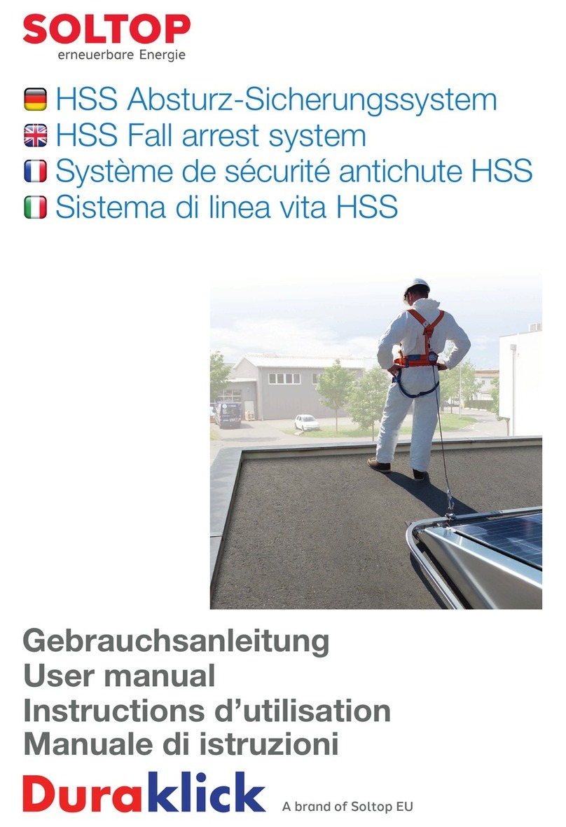
SOLTOP Duraklick HSS User manual

HSS-
Height safety system
Assembly instruction

2
For mounting you need the mounting set:
Drilling template for floor rail for the single
fixing points
Drilling template for floor rail for the single fixing
points
Metal drill 11,5 mm, 10,5 mm und 8,0 mm
2 x Special drill for sinking of the fitings
2 x Ratchet wrench 17 mm
Allen Key 6 mm
Socket Wrench 8 mm
Metal file
Yardstick or tape measure
+ Cordless screwdriver
+ Assembly paste for stainless steel screws
(please order as well)
Introduction and Overview
The Duraklick height safety system
consists of the following components:
Fitting pieces are made
during assembly
step in / out
HSS-rail in different lengths 1m, 3m und 6m
rail curve e.g. 90 ° also available in
other angles
rail connector rail switch
single fixing point
Spacer
(optional to raise the
system)
Each HSS comes with two „equipment sets“. These bags contain the
equipment necessary for securing one person
rail runner
Full body harness
Guided Fall Arrest Device
Type AM4 with shock
absorber
clap rail runner
(optionally)
fixing point with cantilever
hight safety
device
7
8
9
9
8
Assembly paste for stainless
steel screws
(please order as well)

3
TIP Photograph roof
damage!
The Duraklick HSS is a personal safety device and was spe-
cially developed for the Duraklick PV mounting systems. It can
be installed on all systems (SR, EW, GR and ECO). The safety
system may only be installed by Duraklick certified fitters. It
must be installed according to the specifications in these in-
stallation instructions.
1. Anchor devices
Anchor devices Type D and E according to DIN EN 795,
CEN/TS 16415:2013 Type: Duraklick-HSS-Hight Safety Sys-
tem tested by DEKRA EXAM GmbH according to dynamic
and static load capacity according to item 4.4.4 und 4.4.5
DIN EN 795:2012 und CEN/TS 16415:2013 am 06.03.2013.
Approved for max. 4 persons at the same time.
2. Equipment sets (case/bag)
The cases/bags containing the equipment sets (safety
harness, fall protection runner, fall arrester/ AM4 fall arrester)
should be stored near the entrance or roof access.
3. Protection during assembly
Please ensure that you are properly secured against falling
during installation! For safety reasons, work in the fall area
must not be carried out alone
Photograph roof damages!
Before installation, it should be checked whether there is any
damage of any kind - especially water seepage or damage
to the roof cladding. These should be documented with the
digital camera to avoid later recourse claims.
Clean roof
Drilling and metal chips must be removed from the roof! Do
not place any screws or sharp tools on the roof foil!
The roof membrane could be damaged!
General instructions and preparations
Clean roof!
!
The installation of the HSS height safe-
ty system may only be carried out by a
certified fitter.
Attention!
!
Gloves!
Wear gloves during assembly!
Risk of injury from sharp edges!
!
Instruction manual

4
1. Planning and requirements
Each Duraklick and HSS system is planned by Soltop
for the respective PV system and the installing
company receives an installation plan.
1. Delivery check
Immediately after delivery, check the components for
completeness and possible damage.
1
2
3
4
5
6
7
8
9
10
11
12
13
13 12 11 10 9 8 7 6 5 4 3 2 1
Feld Grundschule
Breite: 22.66 m
Länge: 24.96 m
Leistung: 39.62 kWp
Modulanzahl: 139
Sprungmaß: 2.00 m
Modullänge: 1.690 m
Module pro Reihe: 13
Anzahl Reihen: 13
30
we
g
fallende Module:
Objektname:
DE_München_Emmy-Noether-
Straße_200099
Kommission:Grundschule / Leopoldsed erstellt von: uwe.lorinser
erstellt am: 28.02.20 08:15
Feld 1 von 1
Schraffierte Fläche ist Überstand und kann ab
g
elän
g
t werden
Lageplan
2
,
70m Dur
a
4
,
70m Dur
a
6
,
00m Dur
a
Dehnun
g
skl.
zz
xx xx x xx
x x x x
xxxxxx
x xx xxx
#
#
4x6m
4x6m
4x6m
1x3m
1x3m
12x6m
4x Kurve
2x ein+aus
12x Lang
11x kurz
108m Seil
100 Klemmen
3x Motagepaste
1x Sperrschild
25 Verbinder
Key:
Guide rail
+Switch - 3 or 4 track
OEndstop
#Entry / Exit
xAnchor point HSS-D long
xAnchor point HSS-D short
xAnchor point 45°
Wire rope stainless 5mm

5
1.Checking the conditions
Before starting the installation, check the dimensions
and specifications in the planning with the actual condi-
tions. It is possible that a PV system was built differently
than originally planned.
Very important:
- Minimum compound
Minimum size of the module field must be 3 x 4
modules. The minimum weight of the plant must be
460.00 kg (incl. ballast).
Position of the entry/exit
For safety reasons, the entrances must be at least
2.50m away from the nearest fall edge. The entry can
also be integrated into existing guardrails or railings.
(Not applicable for a ring installation. Here there are no
entrances and the folding fall protection runners are
used).
Placement of the anchor points
The anchor points are mounted on the floor rails. The
standard distance is 3 m to 4.5 m - only in special
cases a distance of up to 6 m is permitted.
Requirements for the floor rails
Don´t install short rails (0.70 m and 1.40 m) at the be
ginning and end of a composite where anchor points
are to be installed.
The profile connectors ot the floor profiles can only
withstand a maximum of 9 kn, so short rails must
always be placed in the middle of the compound or
secured accordingly.
2. Important dimensions
Disantance floor rail to support: min.15cm
Minimum compound 3 x 4 modules
Distance from entrance to roof edge of min. 2.50 m
Distance from floor rail to windshield: min.15cm
minimum 2,50 m
Standard distance of anchor points is 3m to 4,50 m

6
3. Installation of the achor points (short)
Lubricate the threads and screws with anti size paste
Put the first anchor point into the foor rail
Attach and screw on load distribution plate
Drill holes in floor rails with drilling template
1. Position of the short anchor
points
The short anchor point must be mounted at least
20 mm from the end of the floor rail. So choose the
distance of the drilling template accordingly.
2. Drilling
Drill the 4 holes for mounting the single point stop with
11.5 mm drill bit. Please use the original HSS drilling
template to drill the holes exactly.
3. Grease the components
The threads of the stainless steel nuts in the anchor
points must be completely greased with anti-seize
assembly Paste
4. Assembly of the front anchor
points (short)
Insert the two halves of the anchor point into the bot-
tom rail and fix them with the supplied stainless steel
screws - but do not tighten them!
The two screws (M10) must be greased before
insertion, otherwise the stainless steel nuts may seize
when tightened.
5. Tightening
Stainless steel screws (M10 x 25) are screwed to the
base plate from the outside through the floor rails with
the anchor point. (Tightening torque = 25 Nm)
Option: Lifting with spacer
In the case of green roofs or elevated gravel, the
spacers can be used. They raise the guide rails.
Drilling and metal chips must be
removed from the roof!
ATTENTION!
!
Distance of min. 20 mm to the end of the floor rail
Always grease screws!
If stainless steel screws and nuts
are not sufficiently greased, there is
a risk that the screws will seize in
the threads when tightened.
ACHTUNG!
!

7
1. Position of the long anchor
points
The lateral (long) anchor points are normally placed
centrally between the modules.
2. Drilling
Drill the 4 holes for mounting the single point stop
with 11.5 mm drill bit. Please use the original HSS
drilling template to drill the holes exactly.
3. Grease the components
The threads of the stainless steel nuts in the anchor
points must be completely greased with anti-seize
assembly Paste
4. Assembly of the lateral anchor
points
Insert the two halves of the anchor point into the bot-
tom rail and fix them with the supplied stainless steel
screws - but do not tighten them!
The two screws (M10) must be greased before
insertion, otherwise the stainless steel nuts may seize
when tightened.
5. Tightening
Stainless steel screws (M10 x 25) are screwed to the
base plate from the outside through the floor rails with
the anchor point. (Tightening torque = 25 Nm)
6. Cantilever mounting
Place the cantilever and fix it with the supplied stainless
steel screws - but do not tighten!
Option: Lifting with spacer
In the case of green roofs or elevated gravel, the
spacers can be used. They raise the guide rails.
4. Installation of the lateral anchor points (long)
Put the second anchor point into the foor rail...
Place the cantilever
…and tighten!
Position of the long anchor points
Drill holes in floor rails with drilling template

8
The lateral anchor points must be connected to the floor
rails behind them by a steel cable. This is the only way
they can absorb and distribute the load in an emergency.
1. Mounting the rope on anchor
points
Guide the wire rope end through the hole provided for
this purpose in the end of the cantilever and fix it with
two rope clamps. (Overlap approx. 30 cm)
2. Feedthrough through floor rail
Guide the steel cable through the bottom rail to the
opposite anchor point (or according to the plan).
Mark the rails at the corresponding position and drill
through with an 8 mm drill bit.
3. Attach rope clamps
Thread 2 rope clamps between each rail and guide the
rope through the holes in the rails.
(If an anchor point is only mounted on one side, one
rope clamp is enough. This must then be mounted on
the opposite side to the anchor point).
Tension the steel rope and fasten it to the opposite an-
chor point with 2 rope clamps. If the anchor point is on
one side, pass it through the last drilled rail and guide
it back. Form a loop with a rope clamp. Now push the
rope clamps onto the rails and clamp them tight.
5. Installation of the wire rope system
Attach rope clamps on each floor rail
Loop on the last floor rail
Rope feedthrough through the floor rail
Tight the rope clamps
Rope system for load introduction into the system
Drilling and metal chips must be
removed from the roof!
ATTENTION!
!

9
1. Insert stainless steel screws
Insert two M10 x 20 stainless steel screws into each of
the guide rails
2. Insert sliding blocks
Place sliding blocks on the EPO to absorb thermal ex-
pansion. The guide collar points upwards - i.e. towards
the rail!
3. Grease and insert screws
Grease the threads of the self-locking stainless steel
nuts with the lubricant supplied.
Guide the two screws through the sliding blocks and
holes on the anchor point.
4. Fixing the guide rail
Fix guide rail with washer and nut but do not tighten
yet!
5. Connecting the guide rails
Insert the corresponding number of M10 x 20 stain
less steel screws into the next rail. Join the rails using
the connectors and screw them together.
6. Finnishing
Fasten the rail as described under point 1 but do not
tighten it!
Repeat this procedure until the next bend or entry
point.
6. Installation of the guide rails
Fixieren of the guide rail
Connecting the guide rails
Insert screws but do not tighten yet!
Insert stainless steel screws
Insert screws through the sliding blocks
Always grease screws!
If stainless steel screws and nuts
are not sufficiently greased, there is
a risk that the screws will seize in
the threads when tightened.
ATTENTION!
!

10
1. Measuring
First measure the distance between the rails to be
connected (minimum distance = 15 cm).
2. Assembling the passport
pieces
Cut best with a chop saw
Drill holes for connectors using the drilling template.
Drill Ø 10.5mm
1. Countersinking holes outside
With sinker 20,5mm 90°
3. Countersinking holes inside
With sinker 12,4 mm 90° with cut tip
7. Assembling the fitting pieces
Measure the distance between the rails
… drilling with the template
… sink the holes outside
… sink the holes inside
Drilling and metal chips must be
removed from the roof!
ATTENTION!
!

11
1. Insert the fitting pieces
Assemble the fitting piece accordingly. Insert it, move
the rails apart a bit to make it easier and screw them
together with connectors.
2. Tightening the rails on the
anchor point
After all rails have been mounted, align the system so
that it is stress-free.
Then tighten all screw connections (M10 x 20) between
rails and anchor point. The torque for stainless steel
screws M10 strength class 70 is 25 Nm.
Finally, check all screw connections for tightness.
3. Assembly of the entrys and
end stops
Please check the position of the entrys before mounting
them. The entry should be at least 2.5 m away from the
nearest fall edge to allow safe use of the HSS-System.
Every entry or end stop must be fixed on an anchor
point and not protrude more than 30 cm above the last
anchor point. Entry or endstop may protrude a maximum of 30 cm
Fixing entry / end-stop
Assemble the fitting piece accordingly.

12
1. Final inspection
Check the system for tight fit of all connecting ele-
ments. Then check the function of the accesses/end
stops.
2. Final testwalk
Check the supplied „equipment set(s)“ (red case/bag)
for completeness and function. Put on the equipment
according to the instructions and perform a test walk
of the system. In particular, check that the entrances
move smoothly and ensure that the fall protection
runner runs smoothly in bends and curves.
3. Fill out acceptance protocol
After completion, fill out the complete
HSS acceptance protocol.
4. Attach type plate
The HSS nameplate should be attached to the HSS
entrance closest to the roof access. It can be stuck
directly onto the guide rail.
5. Attach lock sign
The warning sign indicates whether the system is ready
for operation and use or not (e.g. due to maintenance
or conversion work). Attach the holder in a clearly
visible position either to the roof ladder or to the nearest
HSS entrance and insert the card with the
corresponding side.
6. Providing the equipment sets
The „equipment sets“ (red bag/case) should be stored
in such a way that they are quickly available to any roof
climbers. The ideal place is directly at the roof ascent,
which is dry and easily accessible. The equipment set
should also always contain an HSS instruction manual.
8. Final inspection
Function of the entrance
Attaching the type plate to the next access
Safe working on the roof!
The HSS fall arrest system is
now ready for use.
For the correct use of the sys-
tem, please refer to the instruc-
tions for use enclosed with
each „equipment set“ (red case/
bag).
We wish you safe work!
The warning sign must be on the roof
ascent or on the system.

13
SOLTOP EU GmbH
Sonnenhalde 5
D-88161 Lindenberg
www.soltop.eu
Hauptsitz Schweiz:
SOLTOP Schuppisser AG
St. Gallerstrasse 3 + 5a
CH-8353 Elgg
www.soltop.ch
Sitz der Gesellschaft:
Lindenberg
Registergericht: Kempten
(Allgäu)
Geschäftsführer:
Andreas Zimmerer
Handelsregister: HRB 14331
MwSt: 127/137/60143
UID: DE300491338
EORI: DE314291943832627

14
© SOLTOP EU GmbH • Montageanleitung HSS dt. • Printed in Germany 3/2020 • Änderungen vorbehalten!
Version: 03/ 2020
SOLTOP EU GmbH
Sonnenhalde 5
D-88161 Lindenberg
www.soltop.eu
Hauptsitz Schweiz:
SOLTOP Schuppisser AG
St. Gallerstrasse 3 + 5a
CH-8353 Elgg
www.soltop.ch
Sitz der Gesellschaft:
Lindenberg
Registergericht: Kempten
(Allgäu)
Geschäftsführer:
Andreas Zimmerer
Handelsregister: HRB 14331
MwSt: 127/137/60143
UID: DE300491338
EORI: DE314291943832627
Table of contents
Other SOLTOP Safety Equipment manuals