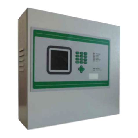
Somati system SLIDETRONIC II User manual

Platné od: 7.3.2017
Somati system s.r.o., Jihlavská 510/2c, 664 41 Troubsko
IČ: 29260159, DIČ: CZ29260159
tel: +420 547 427 011, www.somati-system.cz
02/2017
CONTROL PANEL SLIDETRONIC II
Producer: Somati system s.r.o.
Jihlavská 510/2c
664 41 Troubsko, okr.Brno - venkov
Tel.: 547 427 011
Fax: 547 427 013
www.somati-system.cz

Platné od: 7.3.2017
Somati system s.r.o., Jihlavská 510/2c, 664 41 Troubsko
IČ: 29260159, DIČ: CZ29260159
tel: +420 547 427 011, www.somati-system.cz
02/2017
Contents
1. CONTROL PANEL SLIDETRONIC II...................................................... 1
2. CONFIGURATION ................................................................................ 2
3. INSTALLATION AND SETUP................................................................. 2
4. FUNCTIONS OF THE CONTROL PANEL SLIDETRONIC ii ...................... 3
5. DESCRIPTION OF INTERNAL TERMINAL ............................................ 4
6. DESCRIPTION OF SETTINGS OF DIP SWITCH FUNCTIONS ................ 4
7. DESCRIPTION OF FUNCTION WITH INDIVIDUAL SYSTEMS OF GATES
SOMATI SYSTEM.................................................................................. 6
8. RECOMMENDED EXTERNAL DEVICES.................................................. 7
9. ELECTRICAL AND DIMENSION DATA .................................................. 7
10. DIAGRAMS .......................................................................................... 8
11. DECLARATION OF CONFORMITY......................................................... 9

Platné od: 7.3.2017
Somati system s.r.o., Jihlavská 510/2c, 664 41 Troubsko
IČ: 29260159, DIČ: CZ29260159
tel: +420 547 427 011, www.somati-system.cz
1
Primarily designed to control gravitational fire closures produced by Somati system s.r.o.
The panel can be also used to control hinged fire closures together with electromagnetic
anchors and closers.
1. CONTROL PANEL SLIDETRONIC II

Platné od: 7.3.2017
Somati system s.r.o., Jihlavská 510/2c, 664 41 Troubsko
IČ: 29260159, DIČ: CZ29260159
tel: +420 547 427 011, www.somati-system.cz
2
2. CONFIGURATION
Project Slidetronic II solves control of magnets (brakes) of fire gates. Power of control
circuits can be backed up by an additional battery module, which can keep gate in open
position in case of power failure.
3. INSTALLATION AND SETUP
Before the initial startup, mechanical part of gate installation has to be fully completed to
avoid mechanical damage of the gate during magnet/brake release.
Before first activation connect only:
- power cable
- cable of magnet/brake
- terminals EPS (10 and 11) NC contact (during the contact disconnection, the panel is in
alarm)
- if Slidetronic II is equipped with a battery module, connect the battery to control
panel, the battery is delivered in disconnected status –there is an insulator
between the battery contact, which has to be removed (see the Picture 2: Battery
Module)
- check if the resistance 4.7 kΩ is connected to the terminals 1, 2 (if the resistance is
not connected, the panel is in alarm)
Control panel Slidetronic II is standardly equipped with a keyboard with "Start / Stop"
buttons and also "Reset" button, which causes reset of the panel in case of alarm raised
by local sensors. Gate can be stopped by the STOP button at any time.
When opening the control panel, be careful to avoid damage of printed cable placed
between the keyboard and PCB.
When you activate the EPS –contact between 10 and 11 is disconnected and panel is in
alarm. In case of connection of the contacts, the panel is automatically in standby mode.
In case of power failure, voltage is kept approximately 1 hour and then the power supply is
disconnected in 8, 9 and the panel goes into standby mode.
IF ANY FUSES IN THE SWITCHBOARD ARE BLOWN, THEY CAN BE REPLACED
ONLY ONCE. IF THEY ARE BLOWN AGAIN, THEIR REPLACEMENT IS NOT
PERMITTED.
IF THE PROCEDURE STATED IN THE TECHNICAL DOCUMENTATION IS NOT
RESPECTED, IT MAY LEAD TO THE LOSS OF WARRANTY.
IN THE EVENT OF MALFUNCTION, AT FIRST, IT IS NECESSARY TO DETECT THE
POSSIBLE CAUSE OF THE MALFUNCTION AND REPAIR IT. AFTER THE
MALFUNCTION IS REPAIRED, IT IS POSSIBLE TO REPLACE THE BLOWN FUSE.
IT IS FORBIDDEN TO MANIPULATE WITH THE CIRCUITS OF THE
SWITCHBOARD AND CHANGE THEIR CONNECTIONS. IF THIS CONDITION IS
NOT COMPLIED, IT IS NO LONGER POSSIBLE TO APPLY THE SWITCHBOARD
WARRANTY.
THE SWITCHBOARD CANNOT BE OPENED BY A PERSON WITHOUT AN
APPROPRIATE TRAINING AND QUALIFICATION ACCORDING TO THE DECREE
NO. 50/1978, § 6.

Platné od: 7.3.2017
Somati system s.r.o., Jihlavská 510/2c, 664 41 Troubsko
IČ: 29260159, DIČ: CZ29260159
tel: +420 547 427 011, www.somati-system.cz
3
Operating temperature of the Slidetronic II switchboard is from +10°C to +35°C. If the
ambient temperature is lower than +10 °C or higher than+35 °C, the switchboard cannot
be used! Temperatures above +25 °C and under +15 °C, cause shortening of battery life.
Exceptionally, the Slidetronic II switchboard can be operated at lower temperatures,
maximally to −5 °C, on condition that the input power is permanently connected to
provide minimal warming of the control circuits.
4. FUNCTIONS OF THE CONTROL PANEL SLIDETRONIC II
LED switch plate:
LED (green LED) = network (voltage 230 V)
- On = network is connected
- Flashing = no network (if the battery is connected)
- Off = stopped activity (no voltage 230 V and no battery)
LED (red LED) = movement of gate
- On = gate is not moving
- Flashing = gate is closing
LED (yellow LED) = battery status
- On = charged over 3,9 V
- Flashing = battery is charging
- Off = discharged or no battery
LED (red LED) error (!)
- 1flash = alarm of detectors
- 2 flash = alarm of EPS
If the two alarms are activated at the same time, they are displayed sequentially i.e. one
flash –pause –two flashes.
Note: If the battery is in the device and there is a power failure, the standby mode is
activated. Voltage of the battery falls below 3.3 V, the unit goes into standby mode, turns
off all relays, disconnects the detectors, reduces its own consumption and repeatedly after
35 s., the LEDs gradually flash on the swich plate from left to right.
START/STOP
RESET
START/STOP
Figure 1: Control Panel

Platné od: 7.3.2017
Somati system s.r.o., Jihlavská 510/2c, 664 41 Troubsko
IČ: 29260159, DIČ: CZ29260159
tel: +420 547 427 011, www.somati-system.cz
4
5. DESCRIPTION OF INTERNAL TERMINAL
Input side:
1 –detectors 0 V –closed 4,7 kΩ loop for connection of
detectors between 1 and 2
2 –detectors +24 V –closed 4,7 kΩ loop for connection of
detectors between 1 and 2
10,11 –EPS –potential-free contact NC
11,12 –START/STOP potential-free buttons –NO contact (external button)
Output side:
3 –COM
4 –NO
5 –NC
6 –warning light +24 V
7 –warning light 0 V
8 –brake/magnet +24 V
9 –brake/magnet 0 V
6. DESCRIPTION OF SETTINGS OF DIP SWITCH FUNCTIONS
Controls:
DIP 1 output for warning light
ON = flashing only during alarm
OFF = flashing always when movement is detected
DIP 2 ON = time of brake release is set by trimmer T2 0–130 s.
OFF = brake release has no time limit
DIP 3 ON = time of brake activation is set by trimmer T2x3 = 0-390 s. (DIP 3 is
valid for new devices from 2015, older devices are without the function)
OFF = brake activation has no time limit
DIP 4 no function
Trimmer T1 time of pre-flashing 0-13 s. (from program version V2.3 it is 0-51 s.)
After pressing the START button, siren is activated at first and after passage of the set
time, the gate starts closing.
Trimmer T2 time of release 0 –130 s.
It is an adjustable time during which, after pressing START button, the brake is released.
After passage of the set time the brake is activated again (by recovery of voltage in
terminals 8, 9). Time T2 is normally set the way that after complete closure of gate,
release of brake lasts another 10 seconds and then is activated again.
By setting of time T2 there is automatically set time of brake activation on triple value of
brake release (in case DIP 3 = ON).
output relay max. 60 V/3 A
max. 0,1 A
max. 0,1 A

Platné od: 7.3.2017
Somati system s.r.o., Jihlavská 510/2c, 664 41 Troubsko
IČ: 29260159, DIČ: CZ29260159
tel: +420 547 427 011, www.somati-system.cz
5
Description of DIP 3 function–time of brake activation:
- After power reboot or pressing keyboard button, the brake is activated for the time
3 x T2, then is released again.
- After returning from alarm, EPS activates the brake and after the time 3 x T2 it also
releases the brake.
- After pressing keyboard button or external button for release, brake is released
permanently if DIP2 is OFF , in case DIP2 is ON, brake is released for T2, then is
activated for time 3 x T2, and after that is released permanently.
Changes are valid for devices from 2015, which has label SLIDE-II_V2.1, older devices
(without label SLIDE-II_V2.1) do not have DIP 3 function.

Platné od: 7.3.2017
Somati system s.r.o., Jihlavská 510/2c, 664 41 Troubsko
IČ: 29260159, DIČ: CZ29260159
tel: +420 547 427 011, www.somati-system.cz
6
7. DESCRIPTION OF FUNCTION WITH INDIVIDUAL SYSTEMS OF
GATES SOMATI SYSTEM
A. System of electromagnet
In case of fire, the central unit of fire alarm system or local detectors send a signal into
the control panel which releases electromagnet holding the gate in open position. After
the magnet is released the gate is closed gravitationally (using an inclined rail). After
alarm of local detectors and the reactivation of the system, it is necessary to RESET
the control panel (Figure 1: Control Panel) pressing the RESET button.If there is not
installed a backup power, the gate also closes in case of power failure. During normal
operation, the leaf can be opened manually with recessed handles and closed by
pressing START-STOP buttons on the control panel (Picture 1: Control Panel). By
pressing the START-STOP buttons once again, the voltage 24V on magnet is restored
and gate stays in open position (due to the magnet). When opening the fire closure,
please, take extra care to avoid mechanical damage of the magnet and its function –
especially, when the gate is almost closed to the end position (max. opening), it is
necessary to reduce the speed of closing (to minimize the impact on the
electromagnet).
B. System of electromagnetic brake:
In case of fire, the central unit of fire alarm system or local detectors send a signal
into the control panel which releases electromagnetic brake holding the gate in open
position. After the el. brake is released the gate is closed using counterweight system.
After alarm of local detectors and the reactivation of the system, it is necessary to RESET
the control panel (Figure 1: Control Panel) pressing the RESET button.If there is not
installed a backup power, the gate also closes in case of power failure. During normal
operation, the leaf can be opened manually with recessed handles and closed by
pressing START-STOP buttons on the control panel (Picture 1: Control Panel). By
pressing the START-STOP buttons once again, the gate stops. The advantage of the
system is that it enables to stop the gate in any position and also to regulate the
closing speed directly on electromagnetic brake.

Platné od: 7.3.2017
Somati system s.r.o., Jihlavská 510/2c, 664 41 Troubsko
IČ: 29260159, DIČ: CZ29260159
tel: +420 547 427 011, www.somati-system.cz
7
8. RECOMMENDED EXTERNAL DEVICES
- light and acoustic signalization, siren + warning light FLASHNI mark., FL/RL/T/D, 24 V DC, 1 W
- electromagnetic brake LINNIG SB 3.3.0, 24 V DC, 2,2 W
- electromagnet MEC@Fire M05411D, 24 V DC, 1,6 W
- base of detector SS with the resistor 470 Ohm, mark. B401R, optical smoke
detector mark.2351E or thermo-differential detector 58 °C mark.5351E, SYSTEM
SENZOR
- UPS backup power –is not part of the set (additional batteries can be
purchased). Battery Lion 3.7 V/2200 mAh - when transported or
disconnected for a long time, it has to be removed from power. When it is
inserted again, polarity has to be kept –otherwise the fuse on the module is
interrupted. Time of the backup function of the battery, fully charged and in
good condition, is about 1 hour assuming own consumption and usage of
brake (24 V - 0.1 A) or warning light (24 V - 0.08 A). New battery can reach
2 hours. Fully charged battery requires approx. 10 hours of charging.
9. ELECTRICAL AND DIMENSION DATA
Voltage 230 V/50 Hz
Power input 10 VA
Output brake max. 24 V/0,1 A
Output alarm max. 24 V/0,1 A
Relay alarm 60 V/3 A
Output detectors 24 V
Backup battery 3,2 V/2,2 Ah
Backup time about 1 hod.
Protection IP 54
Panel size H: 20 cm; W: 14 cm; D: 8 cm
Working temperature from -15 to +35 °C (lower temperatures cause reduction of backup time)
Grommets (3 pieces) supplied in the package have to be drilled according to the
dimensions. Standardly the grommets are not drilled. They have to be drilled according to
the location of cables (from the top or the bottom).
insulator
Picture 2:Battery Module

Platné od: 7.3.2017
Somati system s.r.o., Jihlavská 510/2c, 664 41 Troubsko
IČ: 29260159, DIČ: CZ29260159
tel: +420 547 427 011, www.somati-system.cz
8
10. DIAGRAMS
2 types of detector slots (D + H or B401R)
2
2
1
1
DETECTOR SLOTS
Cable installation to
the control panel
Installation of the Battery Module
Complete connections
connections

Platné od: 7.3.2017
Somati system s.r.o., Jihlavská 510/2c, 664 41 Troubsko
IČ: 29260159, DIČ: CZ29260159
tel: +420 547 427 011, www.somati-system.cz
9
11. DECLARATION OF CONFORMITY
Table of contents
