SOMFY animeo Solo Series User manual

© 2007, SOMFY SAS. ALL RIGHTS RESERVED. REF. 5053517 – 01/11/07
somfy.com
UK SE DK ES FR HU IT NL NO PT RO FI CZ DE PL
Installation guide
UK SE DK ES FR HU IT NL NO PT RO FI CZ DE PL
Installationshandbok
UK SE DK ES FR HU IT NL NO PT RO FI CZ DE PL
Installationsvejledning
UK SE DK ES FR HU IT NL NO PT RO FI CZ DE PL
Guía De Instalación
UK SE DK ES FR HU IT NL NO PT RO FI CZ DE PL
Guide D’installation
UK SE DK ES FR HU IT NL NO PT RO FI CZ DE PL
Telepítési Útmutató
UK SE DK ES FR HU IT NL NO PT RO FI CZ DE PL
Guida all’installazione
UK SE DK ES FR HU IT NL NO PT RO FI CZ DE PL
Installatiehandleiding
UK SE DK ES FR HU IT NL NO PT RO FI CZ DE PL
Installasjonsveiledning
UK SE DK ES FR HU IT NL NO PT RO FI CZ DE PL
Guia De Instalação
UK SE DK ES FR HU IT NL NO PT RO FI CZ DE PL
Ghid De Instalare
UK SE DK ES FR HU IT NL NO PT RO FI CZ DE PL
Asennusopas
UK SE DK ES FR HU IT NL NO PT RO FI CZ DE PL
Instalacní prírucka
UK SE DK ES FR HU IT NL NO PT RO FI CZ DE PL
Installationsanweisung
UK SE DK ES FR HU IT NL NO PT RO FI CZ DE PL
Przewodnik Instalacji
animeo®Solo
1 zone: 1860143
2 zone: 1860144
UK SE DK ES FR HU IT NL NO PT RO FI CZ DE PL
Before installation, please read and follow these instructions.
An incorrect installation could lead to serious injury. The product
must be installed by a qualied electrician. SOMFY’s liability
for defects and damages is excluded if they were caused by
disregard of the instructions. Keep these instructions for future
reference.
UK SE DK ES FR HU IT NL NO PT RO FI CZ DE PL
Före installation, läs noggrant igenom denna manual och följ se-
dan instruktionerna. En felaktig installation kan medföra livsfara.
Produkten skall installeras av behörig elektriker. SOMFY’s åta-
ganden gäller ej om installation inte utförts enligt instruktionerna.
Spara manualen för framtida bruk.
UK SE DK ES FR HU IT NL NO PT RO FI CZ DE PL
Læs disse vejledninger omhyggeligt inden produktet installeres.
En forkert installation kan medføre alvorlige kvæstelser. Produk-
tet må kun installeres af en autoriseret elektriker. SOMFY er ikke
ansvarlig for fejl og skader, som opstår som følge af at vejlednin-
gerne ikke følges. Gem denne vejledning til fremtidig brug.
UK SE DK ES FR HU IT NL NO PT RO FI CZ DE PL
Antes de la instalación lea y siga estas instrucciones. Una insta-
lación incorrecta puede signicar accidentes graves. El producto
debe ser instalado por un electricista profesional. La respon-
sabilidad de SOMFY por defectos y averías queda anulada si
los problemas se producen por no seguir estas instrucciones.
Guarde estas instrucciones para el uso futuro
UK SE DK ES FR HU IT NL NO PT RO FI CZ DE PL
Avant l’installation, prière de lire et d’appliquer les présentes ins-
tructions. Une installation incorrecte peut en effet provoquer des
blessures graves. Le produit doit être installé par un électricien
qualié. La responsabilité de SOMFY en cas de défauts et de
dommages est exclue si ceux-ci sont dus à la négligence des
instructions. Prière de conserver ces instructions en vue d’une
utilisation future.
UK SE DK ES FR HU IT NL NO PT RO FI CZ DE PL
A telepítés megkezdése előtt, kérjük, olvassa el, és kövesse az
alábbi utasításokat. Egy helytelen telepítés súlyos károsodás-
hoz vezethet. A terméket egy képzett elektrotechnikusnak kell
telepítenie. A SOMFY nem vállal felelősséget azokért a károkért
és hibákért, amelyek a telepítési utasítások gyelmen kívül
hagyása miatt jelentkeznek. Őrizze meg ezeket az utasításokat
a későbbiekre.
UK SE DK ES FR HU IT NL NO PT RO FI CZ DE PL
Leggere attentamente le presenti istruzioni prima dell’installazio-
ne. L’installazione errata può provocare gravi lesioni personali.
Il prodotto deve essere installato da un elettricista qualicato.
SOMFY declina qualsiasi responsabilità per eventuali difetti o
danni in caso di mancato rispetto delle istruzioni. Conservare le
presenti istruzioni in caso di necessità futura.
UK SE DK ES FR HU IT NL NO PT RO FI CZ DE PL
Voordat u met de installatie begint, verzoeken wij u deze instruc-
ties goed te lezen en op te volgen. Een onjuiste installatie kan
ernstig persoonlijk letsel veroorzaken. Dit product moet worden
geïnstalleerd door een erkend installateur. De aansprakelijkheid
van SOMFY voor defecten en beschadigingen vervalt als deze
instructies niet worden opgevolgd. Bewaar deze handleiding voor
toekomstig gebruik.
UK SE DK ES FR HU IT NL NO PT RO FI CZ DE PL
Les og følg disse instruksjonene før du starter installeringen. Feil
installering kan føre til alvorlig skade. Produktet må installeres av
en godkjent elektriker. SOMFY er ikke ansvarlig for skader og feil
som skyldes at instruksjonene ikke er blitt fulgt. Ta vare på denne
veiledningen for fremtidig bruk.
UK SE DK ES FR HU IT NL NO PT RO FI CZ DE PL
Antes de instalar, queira ler e seguir estas instruções. Uma
instalação errada pode causar graves danos. O produto deve ser
instalado por um electricista habilitado. A SOMFY declina qual-
quer responsabilidade por danos causados pelo não seguimento
das instruções. Mantenha estas instruções para uso como
referência no futuro.
UK SE DK ES FR HU IT NL NO PT RO FI CZ DE PL
Înainte de instalare, vă rugăm să citiţi şi să respectaţi aceste
instrucţiuni. O instalare incorectă ar putea duce la vătămări
grave. Produsul trebuie instalat de către un electrician calicat.
Răspunderea SOMFY pentru defecte şi deteriorări este exclusă
în cazul în care au fost cauzate prin nerespectarea instrucţiunilor.
Păstraţi aceste instrucţiuni pentru o consultare viitoare.
UK SE DK ES FR HU IT NL NO PT RO FI CZ DE PL
Lue ennen asennusta nämä ohjeet ja noudata niitä. Virheellinen
asennus voi johtaa vakavaan tapaturmaan. Tuotteen asennus on
jätettävä pätevälle sähköasentajalle. SOMFY ei ole vastuussa
puutteista ja vahingoista, jos ne johtuivat siitä, ettei ohjeita
noudatettu. Pidä nämä ohjeet tallessa.
UK SE DK ES FR HU IT NL NO PT RO FI CZ DE PL
Před instalací si prosím přečtěte a dodržujte následující pokyny.
Nesprávná instalace by mohla vést k vážnému zranění.
Výrobek musí být instalován kvalikovaným technikem. Právní
odpovědnost rmy SOMFY za vady a poškození se zamítá,
jestliže byly způsobeny nedodržením pokynů, uvedených v této
příručce. Příručku uschovejte pro budoucí použití.
UK SE DK ES FR HU IT NL NO PT RO FI CZ DE PL
Vor der Installation bitte die nachstehenden Anweisungen lesen
und beachten. Eine unsachgemäße Installation kann zu ernst-
haften Verletzungen führen. Das Produkt ist von einer Elektro-
fachkraft zu installieren. Die Haftung von SOMFY in Bezug auf
Mängel und Beschädigungen entfällt, wenn die Anweisungen
nicht beachtet werden. Diese Anweisungen sind aufzubewahren.
UK SE DK ES FR HU IT NL NO PT RO FI CZ DE PL
Przed instalacją należy przeczytać poniższe instrukcje. Niepra-
widłowa instalacja może doprowadzić do poważnych obrażeń.
Produkt musi zostać zainstalowany przez wykwalikowanego
elektryka. Firma SOMFY nie ponosi odpowiedzialności za uszko-
dzenia i szkody powstałe w wyniku nieprzestrzegania instrukcji.
Niniejsze instrukcje należy zachować w razie konieczności ich
ponownego zastosowania.
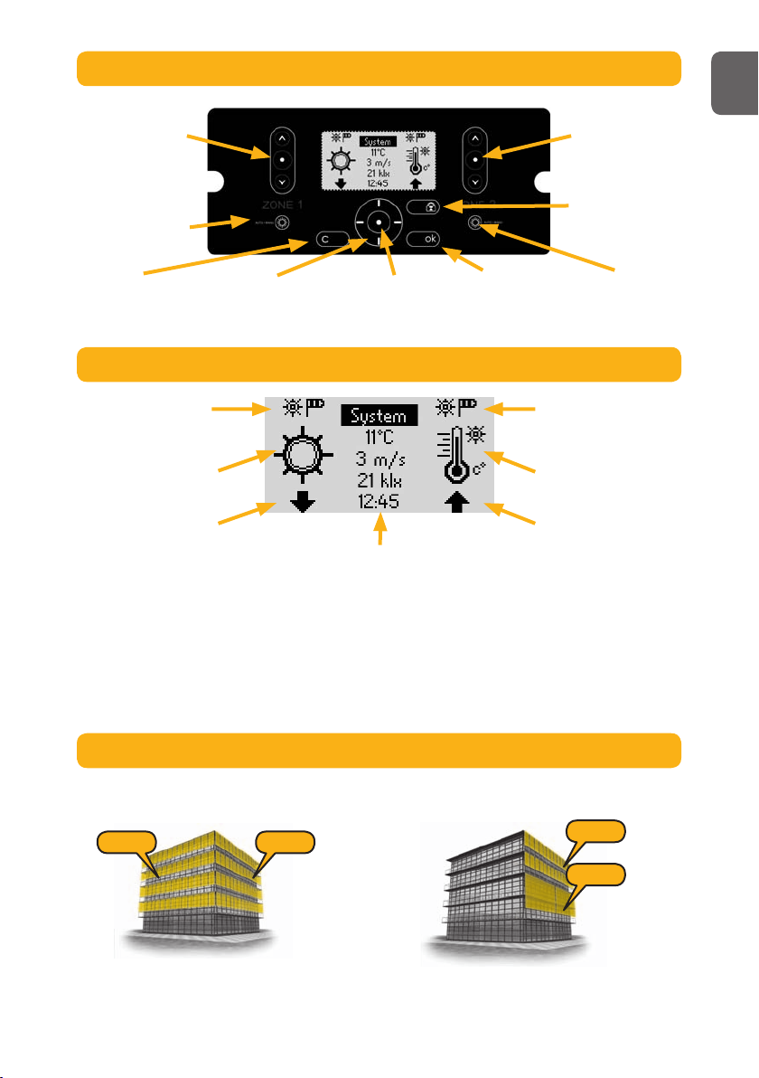
A. EXPLANATION OF USER INTERFACE
3
1. Manual command
up, stop and down
for zone 1.
2. Selector for Manual
and Automatic mode
for zone 1.
3. Cancel and
Back.
4. Navigate up,
down, left and
right on the LCD.
5. Select item. 6. Confirm setting. 7. Selector for
Manual and
Automatic mode
for zone 2.
8. Lock solar
protection up.
9. Manual
command up,
stop and down
for zone 2.
1. Mode zone 1.
Sun+Wind icon = Automatic.
Wind icon = Manual.
2. Active function zone 1.
When flashing the on or off
delay are active.
3. Position zone 1.
Flashing means moving or
locked. 4. Menu selection and information.
a. System: Enter system settings.
b. Present weather information and shortcut to ”Sensor
status”.
c. Time and shortcut to ”Set time”.
Notes:
lIf the control is in ”demo” or ”test mode” the mode
toggles with ”time”.
lBlack background means selected (”System” in this case).
7. Mode zone 2.
Sun+Wind icon = Automatic.
Wind icon = Manual.
6. Active function zone 2.
When flashing the on or off
delay are active.
5. Position zone 2.
Flashing means moving or
locked.
In this example you use one set of wind and sun
sensors per zone.
In this example you normally use the same set of wind
and sun sensors for both zones.
B. LCD EXPLANATION
A zone is a facade with one type of solar protection with the same dimensions.
C. WHAT IS A ZONE?
Zone 2Zone 1 Zone 1
Zone 2
Pic. 1 Pic. 2
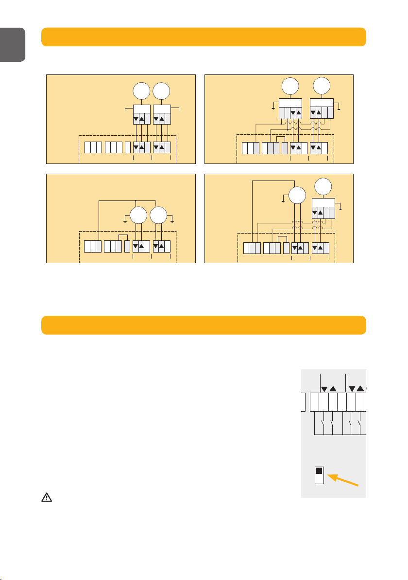
UK

Cabling possible from back and top of the controller.
1 2 3 4 5
12 3 4
5
175
80
4
Wind
Precipitation
Timer Heat Settings Motor
Preserve heat
Get heat
Threshold
- On threshold
Advanced
Use Function
- Function used?
Threshold
- On threshold
- Off threshold
Delay
- On delay
- Off delay
Sensor allocation
- Allocation
System Sensors Time / (Demo) / (Test)
Use Function
- Function used?
Threshold
- Threshold
Delay
- On delay
- Off delay
Sensor allocation
- Allocation
Wind unit
- Unit
Threshold
- Threshold
Advanced
Use Function
- Function used?
Advanced
Use Function
- Function used?
Delay
- On delay
- Off delay
Use Function
- Function used?
Set timer
- Start time
- Stop time
Advanced
Use Function
- Function used?
Set timer
- Start time
- Stop time
Direction
- Set direction
Use Function
- Function used?
Set timer
- Start time
- Stop time
Advanced
Use Function
- Function used?
Set timer
- Start time
- Stop time
Delay
- On delay
- Off delay
Temp. threshold
- Threshold
Use Function
- Function used?
Set timer
- Start time
- Stop time
Advanced
Use Function
- Function used?
Set timer
- Start time
- Stop time
Delay
- On delay
- Off delay
Temp. threshold
- Threshold
Sun threshold
- Threshold
Sensor allocation
- Allocation
Test and Demo
- Select mode
Status
- Functions
- Sensors
Screen Options
- Contrast
- Backlight
- LCD light period (min)
Error list
- Reset error list
Alarm
- Function used?
Clock setting
- Set clock
Language
- Language chosen
Contact info
Network mode
Software version
Factory reset
Set down running time
- Time
Set tilt time
- Time
Advanced
Set down running time
- Time
Set tilt time
- Time
Set up running time
- Time
Advanced
Sun
D. MENU STRUCTURE
E. MOUNTING THE CONTROLLER
UK

C
LLLNNN
Zone 1 Zone 2
PE
Error
+C
E x te rn a l
Co m m an d
Z on e 2
1
+
1
Out
Side
2
2
+
+
C
C
C
Ex t er n al
C o mm a nd
Z o n e 1
RK
IB
CC
PE PE
1 1
Outside22
Zone 2 Zone 1
Animeo Solo to… Cable Max distance Remark
IB/Zone Switch Min: 3 x 0,6 mm2/19 AWG
Max: 3 x 2,5 mm2/ 13 AWG
1000 m/50 m
RK Min: 5 x 1,5 mm2/16 AWG
Max: 5 x 2,5 mm2/ 13 AWG
150 m Incl. protective earth (PE)
Mains (230 V AC) Min: 3 x 1,5 mm2/16 AWG
Max: 3 x 2,5 mm2/ 13 AWG
150 m Incl. protective earth (PE)
Motor (230 V AC) Min: 4 x 1,5 mm2/16 AWG
Max: 4 x 2,5 mm2/ 13 AWG
150 m Incl. protective earth (PE)
Sensor / Key Switch /
Error Output / Alarm
Min: 2 x 0,6 mm2/19 AWG
Max: 2 x 2,5 mm2/ 13 AWG
100 m
”L” to ”C bridge” Min: 1 x 1,5 mm2/16 AWG
Max: 1 x 2,5 mm2/ 13 AWG
Only use in RK mode
5
F. MOUNTING THE SENSORS
Please study the appropriate sensors installation guides.
G. GENERAL WIRING DIAGRAM
UK
C
LLLNNN
Zone 1 Zone 2
PE
Error
+C
E x te rna l
Co m m an d
Z on e 2
1
+
1
Out
Side
2
2
+
+
C
C
C
Ext er n al
C o mm a nd
Z o n e 1
RK
IB
CC
PE PE
1 1
Outside22
Zone 2 Zone 1
C
C C CLLLNNN
IB
230V
IB
C
230V
MotorMotor
Zone 1 Zone 2
C C CLLLNNN
RK
Motor
LN
RK
Motor
LN
Zone 1 Zone 2
C C CLLLNNN
Zone 1 Zone 2
Motor
230V
Motor
230V
C C CLLLNNN
Zone 1 Zone 2
RK
LN
Motor
230V
Motor
Please study the appropriate motor relay’s installation guide.
The number of motors that can be connected in RK mode is dependent on the main fuse
used. Normally you can count one motor per 1A. This means a 10A fuse allows maximum 10
motors to be connected.
IB RK
Motor direct Motor direct
+ RK
6
H. MOTOR CONNECTION PRINCIPLES
Animeo Solo consists of two different modes to control motor relays, IB and RK. Select the type
you are using. IB network mode is default. (The switch is located on the printed circuit board.)
IB network mode
IB is Somfy’s standard communication mode. Typical motor relays
with IB mode are Somfy CD 1x1, Somfy animeo Motor controllers and
Centralis Uno IB.
RK network mode
RK is an older network mode using no electronics or “intelligence” in
the motor relays. A typical motor relay with RK is Somfy RK2. RK mode
is also used when connecting one AC motor directly to the controller.
Important!
It’s very important that you select the correct network mode for your installation. Otherwise
there is risk that you will damage the products. If more than one motor is to be connected
to a zone, a motor relay must be used.
I. SELECT NETWORK MODE
UK

Start up
Language chosen:
English
Next
Start up
Used network mode:
If not correct, change
before you continue! Next
IB
Start up
Set clock
8:20
Next
Motor
Set down running time…
Set tilt time…
Set up running time…
1 sek
25 sek
25 sek
Set running time Set tilting time
IMPORTANT: If you change the network mode,
you must power the controller off and on.
Select language.
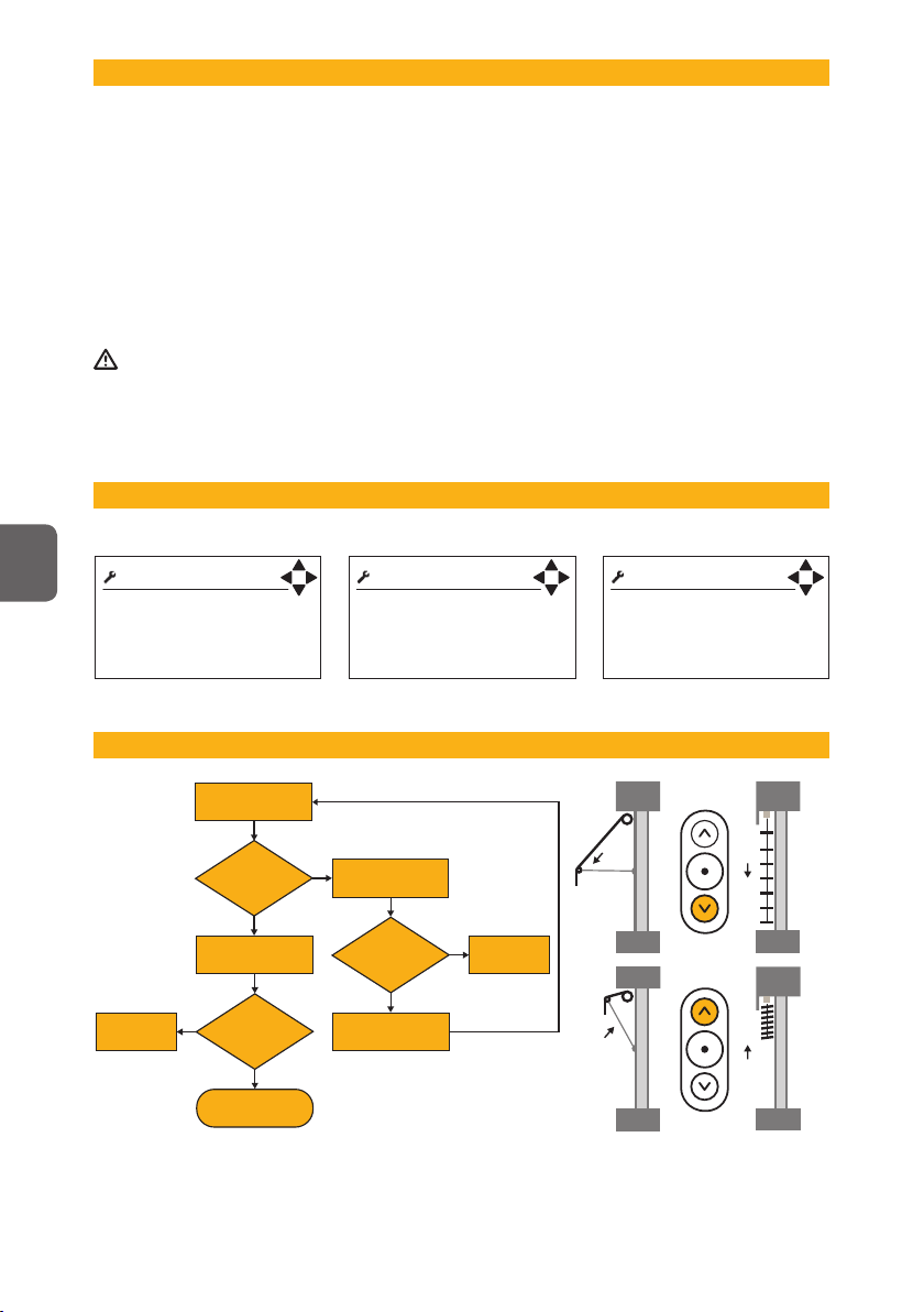
Give a manual up
command for zone 1. Check cabling.
Check cabling. Switch up and down
cable to motor/relay.
Give a manual
up command.
Repeat for zone 2.
Then done.
Give a manual down
command for zone 1.
Solar protection
going down?
Solar protection
going down?
No
No
No
Ye s
Ye s
Ye s
Solar protection
going up?
7
J. POWER UP THE CONTROLLER THE FIRST TIME
K. CHECK MOTOR DIRECTION
Enter the time (down running time) needed for the solar protection to move from fully up/in
position to the position where you want the solar protection to move to when e.g. sun and
timer functions are active.
If blinds are used also enter the time (tilt time) needed for the slats to move from fully
closed to the angle you want when the sun function is active. As a rule of thumb the time
up (up running time) should be double that of the down time (down running time).
To test your running and tilt times make sure that the solar protection is in the fully up/in
position and then give a manual down command.
L. SET MOTOR RUNNING AND TILTING TIME.
UK
/ Sensor status
Sun 1: 12 klx
Sun 2: 12 klx
Wind 1: 12 m/s
Wind 2: 12 m/s
/ Error
Reset error list…
Sun 1: Not connected
Temperature: Short circuit
8
M. CHECK SENSORS
Go to Sensors status. Wind and sun sensors
should normally show a value higher then zero.
If that is the case, then everything is fine. If it’s
very dark use a flashlight on the sun sensor to
simulate sun and check the value. If there’s
no wind just turn the windmill manually and
check the value. If you have more then one
sun and/or wind sensor make sure that the
corresponding sensor is connected to the correct input. The easiest way of doing this is to
cover one sensor and then check the value/s.
N. ERRORS
Check Error list if any errors.
If yes, consult the owners manual.
O. SETTINGS
The settings depend on the functions to be used. For detailed information, please see the
owner’s manual.
The minimum settings are listed below:
lDisable functions that are not to be used. Especially important for wind, sun and heat
functions as they will generate errors if the referring sensor is not connected.
lSensor allocation for wind and sun, if more then one sun and/or wind sensor are used.
lWind threshold. For exact values please contact the solar protection supplier.
The table below is for guidance only:
lIf Alarm function is to be used, enable function.
Type Wind Speed
m/s km/h Mph
Façade awning / Screen 10 36 22
External Venetian blind 15 54 33
Folding arm awning 8 28 18
UK
Tip when testing
If you want to test a function, e.g. the sun, you have to wait for the on and off delays.
By setting the controller to test mode all delays will be shortened by a factor of 60.
Important! Do not forget to return to normal mode when finished.
9
nWhy do the solar protection go down when I press the Up button (or vice versa)
There is an error in the wiring (see section G+H+I+K).
nThe solar protection does not go sufficiently low when the sun shines.
Increase the down running time (see section D+L).
nThe blinds do not tilt enough when the sun shines.
Increase the tilt time (see section D+L).
nI can’t move the solar protection manually
Check LCD to see if any blocking function is active (e.g. wind) (see section B+D).
nThere is sun but the solar protection is not down.
Is the control in automatic mode? (See section A+B).
Is the sun function enabled? (See section D+O).
Check LCD to see if any blocking function is active (e.g. Wind, Timer, Error or Get Heat) (see section B+D).
Is there sun on the sun sensor?
Perhaps your sun on threshold is set to high? Check present sun value in sensor status and
compare with your “On threshold” (see section B+D+M).
Is the sensor allocated correctly? (See section D+M+O).
nThere is no sun but the solar protection is down.
Is the control in automatic mode? (See section A+B).
Is the sun function enabled? (See section D+O).
Check LCD to see if any blocking function is active (e.g. Preserve Heat ,Timer) (see section B+D).
Is there sun on the sun sensor?
Perhaps your sun up threshold is set to low? Check present sun value in sensor status and
compare with your on threshold (see section B+D+M).
Is the sensor allocated correctly? (See section D+M+O).
nThe solar protection moves to often up and down during a partially cloudy day
Increase “sun off” and “sun on” delay (see section D+O).
nIt’s very windy but the solar protection is still out.
Is wind function enabled? (See section D+O).
Is wind sensor turning?
Is the wind sensor mounted in adequate position?
Perhaps your wind threshold is set to high? Check present wind value in sensor status and
compare with your threshold (see section B+D+M).
Is the sensor allocated correctly? (See section D+M+O).
nNothing seams to work as it used to do
Check if there is an error indicated on the LCD or in the error list (see section B+D+N).
Contact your supplier or www.somfy.com
P. FAQ
UK
10
Q. COMPATIBLE SENSORS & SWITCHES
Ref.No. Type Description
9 101 479
Out-
side
(wind) Eolis wind sensor
9 154 217
Out-
side
(sun) Soliris sun sensor
9 154 080
Out-
side
(wind + sun) Soliris combi sensor
1 800 278
Out-
side
(switch) Centralis IB (double push button)
9 001 611
Out-
side
(outside temp. sensor) Temperature Sensor Outside
9 709 808
Out-
side
(thermostat) Inside thermostat
9 705 588
Out-
side
(rain) Rain sensor (230 V, dry contact)
9 001 610
Out-
side
(rain) Rain sensor (24 V, dry contact) *
9 011 235
Out-
side
(rain) Rain sensor aquatic
R. TECHNICAL DATA
Supply Voltage 230 V AC
Frequency 50 Hz
Max. operating current (primary) Stand-by: 12,5 mA (=1W) (typical)
Backlight: 20 mA (=1,3W) max
Mechanical data Housing Wall mounted
Length / Height / Width 225 mm / 149 mm / 49 mm
Weight 540 g
Housing material ABS (recyclable)
Protection code IP 20
Input General Short circuit secured
Major alarm input 15 V DC Normally closed (NC)
Switch Double push button (C, UP, DOWN)
Potential free output Error Dry contact, normally closed (NC), 24 V max 1 A
Motor output Relay 250 V, 3.15 A, cos F= 0.95
Temperature range Operating temperature 0 to 45 ˚C
Storage temperature -20 to 70 ˚C
Relative humidity 85%
Conformity CE by EN 60730-1
* = additional power supply needed
UK

36
Leggere attentamente le presenti istruzioni prima dell’installazione. L’installazione errata
può provocare gravi lesioni personali. Il prodotto deve essere installato da un elettricista
qualificato. SOMFY declina qualsiasi responsabilità per eventuali difetti o danni in caso di
mancato rispetto delle istruzioni. Conservare le presenti istruzioni per riferimento futuro.
➽ Dati tecnici e Accessori sono riportati a pagina 10.
➽ Vedere il capitolo in Inglese (UK) per le figure.
A. Descrizione dell’interfaccia dell’utente vedere pag. 3
1. Comando manuale Salita, Stop e Discesa per la zona 1.
2. Selettore modalità Manuale e Automatica per la zona 1.
3. Annulla e Indietro.
4. Navigatore sù, giù, destra, sinistra sul display LCD.
5. Selezione.
6. Conferma impostazione.
7. Selettore modalità Manuale e Automatica per la zona 2.
8. Blocco protezione solare in fine corsa alto.
9. Comando manuale Salita, Stop e Discesa per la zona 2.
B. Descrizione del display LCD vedere pag. 3
1. Modalità zona 1. Icona Sole+Vento = Automatico. Icona Vento = Manuale.
2. Funzione attiva zona 1. Quando lampeggia è attivato il ritardo di comparsa o scomparsa.
3. Posizione zona 1. Lampeggia durante il movimento o il blocco.
4. Selezione menu e informazioni.
a. Sistema: Inserimento impostazioni di sistema.
b. Visualizzazione informazioni meteo, selezione rapida di “Stato sensori”.
c. Orologio e selezione rapida di “Regola orologio”.
Note:
lSe il controllo è in modalità “Demo” o ”Test”, è possibile cambiare modalità con
“Orologio”.
lLo sfondo nero indica l’opzione selezionata (in tal caso “Sistema”).
5. Posizione zona 2. Lampeggia durante il movimento o il blocco.
6. Funzione attiva zona 2. Quando lampeggia è attivato il ritardo di comparsa o scomparsa.
7. Modalità zona 2. Icona Sole+Vento = Automatico. Icona Vento = Manuale.
C. Che cosa è una zona? vedere pag. 3
Una zona è una facciata con una sola tipologia di trotezioni solari con le stresse dimensioni.
In figura 1 viene utilizzato un set di sensori vento e sole per zona.
In figura 2 normalmente viene utilizzato lo stesso set di sensori vento e sole per entrambe le
zone.
UK SE DK ES FR HU IT NL NO PT RO FI CZ DE PL
GUIDA ALL’INSTALLAZIONE
IT

37
D. Struttura dei menu vedere pag. 4
E. Montaggio del controller vedere pag. 4
Il cablaggio può essere effettuato sia dal retro che dal lato superiore del controller.
F. Montaggio dei sensori vedere pag. 5
Fare riferimento alle guide all’installazione dei sensori utilizzati.
G. Schema elettrico generale vedere pag. 5
Vedere lo schema elettrico a pagina 5.
H. Principio di collegamento del motore vedere pag. 6
Fare riserimento alle guide all’installazione dei controlli utilizzati.
Il numero di motori collegabili in modalità RK dipende dal fusibile di rete utilizzato. In genere
è possibile utilizzare un motore per 1 A. Un fusibile da 10 A permette quindi di collegare un
massimo di 10 motori.
Vento
Pioggia/neve
Orologio Calore Settings Motor
Conserva calore
Ottieni calore
Soglia
- Soglia comparsa
Avanzato
Funzione usata
- Usa la funzione?
Soglia
- Soglia comparsa
- Soglia scomparsa
Ritardo
- Ritardo comparsa
- Ritardo Scomparsa
Assegnazione sensori
- Assegnazione
Sistema Sensori Tempo / (Demo) / (Test)
Funzione usata
- Usa la funzione?
Soglia
- Soglia
Ritardo
- Ritardo comparsa
- Ritardo Scomparsa
Assegnazione sensori
- Assegnazione
Unità del vento
- Unità
Soglia
- Soglia
Avanzato
Funzione usata
- Usa la funzione?
Avanzato
Funzione usata
- Usa la funzione?
Ritardo
- Ritardo comparsa
- Ritardo Scomparsa
Funzione usata
- Usa la funzione?
Regola orologio
- Avvio orologio
- Arresto orologio
Avanzato
Funzione usata
- Usa la funzione?
Regola orologio
- Avvio orologio
- Arresto orologio
Direzione
- Scegli direzione
Funzione usata
- Usa la funzione?
Regola orologio
- Avvio orologio
- Arresto orologio
Avanzato
Funzione usata
- Usa la funzione?
Regola orologio
- Avvio orologio
- Arresto orologio
Ritardo
- Ritardo comparsa
- Ritardo
Scomparsa
Soglia temperatura
- Soglia
Funzione usata
- Usa la funzione?
Regola orologio
- Avvio orologio
- Arresto orologio
Avanzato
Funzione usata
- Usa la funzione?
Regola orologio
- Avvio orologio
- Arresto orologio
Ritardo
- Ritardo comparsa
- Ritardo Scomparsa
Soglia temperatura
- Soglia
Soglia luminosità
- Soglia
Assegnazione sensori
- Assegnazione
Test e Demo
- Modo scelto
Stato
- Funzioni
- Sensori
Opzioni Schermo
- Contrasto
- Luminosità
- Attivazione LCD (min.)
Elenco degli errori
- Svuota lista errori
Allarme
- Usa la funzione?
Regolazione dell'orologio
- Config. orologio
Lingua
- Lingua scelta
Informazioni
Rete
Vers. software
Reset configurazione
Definisci tempo discesa
- Tempo
Tempo tilting
- Tempo
Avanzato
Definisci tempo discesa
- Tempo
Tempo tilting
- Tempo
Definisci tempo di salita
- Tempo
Avanzato
Sole
IT
Start up
Language chosen:
English
Next
Avvio
Tipologia di rete:
Se non corretto, cambia
prima di continuare! Dopo
IB
Avvio
Config. orologio
8:20
Dopo
38
I. Selezione della modalità di rete vedere pag. 6
Animeo Solo prevede due tecnologie differenti per il controllo del motore, IB e RK. Selezionare il
tipo desiderato. La tecnologia predefinita è IB. (L’interruttore è situato sul circuito stampato.)
Tecnologia IB
IB è la modalità di comunicazione standard Somfy. Tipici controlli in modalità IB sono ad es. Il
CD 1x1, il Motor Controller animeo e il Centralis IB .
Tecnologia RK
RK è una tecnologia obsoleta priva di elettronica intelligente. Un tipico controllo è il Somfy RK2.
La tecnologia RK viene utilizzata anche per collegare direttamente un motore AC al controller.
Importante!
È molto importante selezionare la tecnologia corretta per la propria installazione. In caso
contrario, si possono danneggiare i prodotti. Qualora si colleghino più motori ad una zona,
deve essere utilizzato un opportuno controllo.
J. Primo avviamento del controller vedere pag. 7
K. Controllo della direzione di rotazione del motore vedere pag. 7
Impartire un comando
manuale salita per la
zona 1.
Controllare il
cablaggio.
Controllare il
cablaggio.
Invertirei fili di salita e
discesa al motore/relè.
Impartire un comando
manuale salita.
Ripetere la procedura
per la zona 2.
Impartire un comando
manuale discesa per la
zona 1.
La protezione
solare si abbassa?
La protezione
solare si abbassa?
No
No
No
Sì
Sì
Sì
La protezione
solare si solleva?
IT
IMPORTANTE: Se si modifica la tecnologia
bisogna togliere e ridare corrente .
Scegliere la lingua.

39
L. Impostazione dei tempi di funzionamento e di tilting. vedere pag. 7
Impostazione del tempo di funzionamento (Set running time)
Inserire il tempo necessario affinché la protezione solare si muova dalla posizione completamente
sollevata alla posizione bassa al momento desiderato, ad es. con le funzioni Sole e Orologio
attivate.
Impostazione del tempo di tilting (Set tilting time)
Qualora si utilizzino le veneziane, inserire il tempo necessario affinché le lamelle si
muovano dalla posizione completamente chiusa all’angolazione desiderata, ad es. con la
funzione Sole attivata.
Di norma, il tempo di sollevamento deve corrispondere al doppio del tempo di abbassamento.
Verificare i tempi di funzionamento e apertura per accertarsi che la protezione solare sia in
posizione completamente sollevata, quindi impartire un comando manuale di discesa.
M. Controllo dei sensori vedere pag. 8
Selezionare “Stato sensori”. In genere, i sensori di vento e sole mostrano un valore maggiore
di zero. In tal caso, è tutto OK. Se è molto buio, illuminare il sensore del sole con una torcia
elettrica per simulare il sole e controllare il valore. In assenza di vento, è sufficiente azionare
manualmente il sensore e controllare il valore. Nel caso di più sensori di sole e/o vento,
accertarsi che ogni sensore sia collegato all’ingresso giusto. A tal scopo è sufficiente coprire
un sensore e controllare il/i valore/i.
N. Errori vedere pag. 8
Verificare gli eventuali errori nell’Elenco degli errori. In caso di errori, consultare il manuale
istruzioni.
O. Configurazione vedere pag. 8
La configurazione dipende dalle funzioni utilizzate. Per informazioni dettagliate, consultare
il manuale istruzioni. Di seguito sono riportate le impostazioni minime raccomandate:
lDisabilitare le funzioni inutilizzate. Questo è particolarmente importante per le funzioni Vento,
Sole e Calore che possono comportare errori se i sensori corrispondenti non sono collegati.
lAssegnazione dei sensori di vento e/o sole in caso di utilizzo di più sensori.
lSoglia del vento. Per i valori precisi, contattare il fornitore della protezione solare. La
seguente tabella contiene solamente valori indicativi:
lAbilitare l’eventuale funzione di allarme.
Tipo Velocità del vento
m/s km/h Mph
Tenda/prot. solare per facciata 10 36 22
Veneziana esterna 15 54 33
Tenda a braccio 8 28 18
IT

40
P. Domande più frequenti
nPerché la protezione solare si abbassa quando premo il pulsante Salita (o viceversa)?
Il cablaggio del motore non è corretto (vedere sezione G+H+I+K).
nLa protezione solare non si abbassa in misura sufficiente con il sole.
Aumentare il tempo di apertura (vedere sezione D+L).
nLe veneziane non si aprono in misura sufficiente con il sole.
Aumentare il tempo di apertura (vedere sezione D+L).
nLa protezione solare non può essere regolata manualmente.
Verificare che non sia attivata una funzione di blocco (ad es. Vento) sul display LCD (vedere sezione B+D).
nLa protezione solare non si abbassa con il sole.
Il controller è in modalità automatica? (Vedere sezione A+B.)
La funzione Sole è abilitata? (Vedere sezione D+O.)
Verificare che non sia attivata una funzione di blocco (ad es. Vento, Orologio, Errore o Ottieni calore)
sul display LCD (vedere sezione B+D).
Il sensore del sole è illuminato?
Probabilmente la soglia di luminosità è troppo elevata. Controllare il valore di luminosità in Stato
sensori e confrontarlo con “Soglia comparsa” (vedere sezione B+D+M).
Il sensore è assegnato correttamente? (Vedere sezione D+M+O.)
nLa protezione solare si abbassa in assenza di sole.
Il controller è in modalità automatica? (Vedere sezione A+B.)
La funzione Sole è abilitata? (Vedere sezione D+O.)
Verificare che non sia attivata una funzione di blocco (ad es. Conserva calore, Orologio) sul display LCD
(vedere sezione B+D).
Il sensore del sole è illuminato?
Probabilmente la soglia di luminosità è troppo bassa. Controllare il valore di luminosità in Stato
sensori e confrontarlo con “Soglia comparsa” (vedere sezione B+D+M).
Il sensore è assegnato correttamente? (Vedere sezione D+M+O.)
nLa protezione solare si abbassa e si alza frequentemente nelle giornate parzialmente nuvolose.
Aumentare il ritardo di “scomparsa” e “comparsa” (vedere sezione D+O).
nLa protezione solare rimane aperta in presenza di vento forte.
La funzione Vento è abilitata? (Vedere sezione D+O.)
Il sensore del vento ruota?
Il sensore del vento è montato in posizione appropriata?
Probabilmente la soglia del vento è troppo elevata. Controllare il valore del vento in Stato sensori e
confrontarlo con la soglia impostata (vedere sezione B+D+M).
Il sensore è assegnato correttamente? (Vedere sezione D+M+O.)
nNulla sembra funzionare come dovrebbe.
Verificare che non sia presente un errore sul display LCD o nell’Elenco degli errori (vedere sezione B+D+N).
Contattare il proprio rivenditore oppure www.somfy.com
Suggerimento per il collaudo
Per testare una funzione, ad es. Sole, è necessario attendere i ritardi di comparsa e scomparsa.
Impostando il controller in modalità Test, tutti i ritardi verranno abbreviati del 60%.
Importante! Non dimenticare di reimpostare la modalità Normale al termine del test.
IT

somfy.com
© 2007 Somfy Nordic AB • 0413-Animeo Solo_IM • 071206
Table of contents
Languages:
Other SOMFY Control Panel manuals


