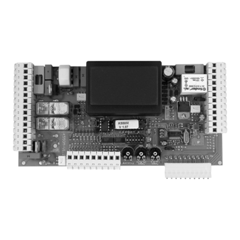
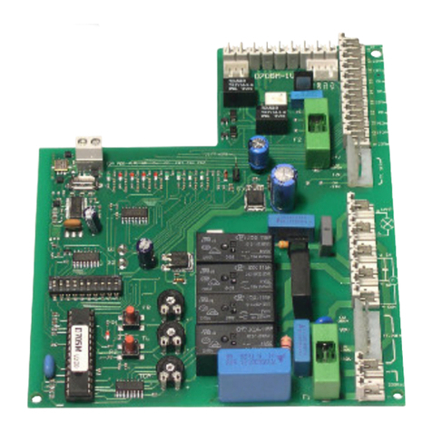
tau D704M User manual

1
D704M
Edizione 02 - anno 2007 rev. 07 del 07/03/2008
http://www.tauitalia.com
D704M
TAU srl via E. Fermi, 43 - 36066 Sandrigo (VI) Italia - Tel ++390444750190 - Fax ++390444750376 - E-mail: info@tauitalia.com
GUIDA ALL’INSTALLAZIONE
INSTALLATION GUIDE
INSTALLATIONSANLEITUNG
NOTICE D’INSTALLATION
GUÍA PARA LA INSTALACIÓN
QUADRO DI COMANDO PER MOTORIDUTTORE MASTER20Q
CONTROL PANEL FOR MASTER20Q GEARMOTOR
SCHALT- UND STEUERTAFEL FÜR DEN GETRIEBEMOTOR MASTER20Q
LOGIQUE DE COMMANDE POUR MOTORÉDUCTEUR MASTER20Q
PANEL DE MANDOS PARA MOTORREDUCTOR MASTER20Q
>ITALIANO
>ENGLISH
>DEUTSCH
>FRANÇAIS
>ESPAÑOL
Revendeur
http://automatismes.lj-system.net

2
D704M
Introduzione
Il presente manuale è destinato solamente al personale tecnico qualificato per l’installazione.
Nessuna informazione contenuta nel presente fascicolo può essere considerata d’interesse per
l’utilizzatore finale. Questo manuale è allegato alla centralina D704M montata sul motoriduttore
MASTER20Q, non deve pertanto essere utilizzato per prodotti diversi!
Avvertenze importanti:
Togliere l’alimentazione di rete alla scheda prima di accedervi.
La centralina D704M è destinata al comando di un motoriduttore elettromeccanico per
l’automazione di cancelli, porte e portoni.
Ogni altro uso è improprio e, quindi, vietato dalle normative vigenti.
È nostro dovere ricordare che l’automazione che state per eseguire, è classificata come
“costruzione di una macchina” e quindi ricade nel campo di applicazione della direttiva europea
89/392 CEE (Direttiva Macchine).
Questa, nei punti essenziali, prevede che:
- l’installazione deve essere eseguita solo da personale qualificato ed esperto;
- chi esegue l’installazione dovrà preventivamente eseguire “l’analisi dei rischi” della macchi-
na;
- l’installazione dovrà essere fatta a “regola d’arte”, applicando cioè le norme;
- infine dovrà essere rilasciata al proprietario della macchina la”dichiarazione di conformità”.
Risulta chiaro quindi che l’installazione ed eventuali interventi di manutenzione devono essere
effettuati solo da personale professionalmente qualificato, in conformità a quanto previsto dalle
leggi, norme o direttive vigenti.
Nella progettazione delle proprie apparecchiture, TAU rispetta le normative applicabili al prodotto
(vedere la dichiarazione di conformità allegata); è fondamentale che anche l’installatore, nel
realizzare gli impianti, prosegua nel rispetto scrupoloso delle norme.
Personale non qualificato o non a conoscenza delle normative applicabili alla categoria dei
“cancelli e porte automatiche” deve assolutamente astenersi dall’eseguire installazioni ed
impianti.
Chi non rispetta le normative è responsabile dei danni che l’impianto potrà causare!
si consiglia di leggere attentamente tutte le istruzioni prima di procedere con l’installazione.
Italiano
Introduction
This manual has been especially written for use by qualified fitters. No information given in this
manual can be considered as being of interest to end users. This manual is attached to the
D704M control unit mounted on the MASTER20Q gearmotor, therefore it may not be used for
different products!
Important information:
Disconnect the panel from the power supply before opening it.
The D704M control unit has been designed to control an electromechanical gear motor for
automating gates and doors of all kinds.
Any other use is considered improper and is consequently forbidden by current laws.
Please note that the automation system you are going to install is classified as “machine
construction” and therefore is included in the application of European directive 89/392 EEC
(Machinery Directive).
This directive includes the following prescriptions:
- Only trained and qualified personnel should install the equipment;
English
D-MNL0D704M

3
D704M
- the installer must first make a “risk analysis” of the machine;
- the equipment must be installed in a correct and workmanlike manner in compliance with all
the standards concerned;
- after installation, the machine owner must be given the “declaration of conformity”.
This product may only be installed and serviced by qualified personnel in compliance with current,
laws, regulations and directives.
When designing its products, TAU observes all applicable standards (please see the attached
declaration of conformity) but it is of paramount importance that installers strictly observe the
same standards when installing the system.
Unqualified personnel or those who are unaware of the standards applicable to the “auto-
matic gates and doors” category may not install systems under any circumstances.
Whoever ignores such standards shall be held responsible for any damage caused by the
system!
Do not install the unit before you have read all the instructions.
Einleitung
Das vorliegende Handbuch ist nur für technisches, zur Installation qualifiziertes Personal bestimmt.
Die im vorliegenden Heft enthaltenen Informationen sind für den Endbenutzer nicht interessant.
Diese Anleitung liegt der Steuerung D704M bei, die an den Getriebemotor MASTER20Q montiert
ist, und darf daher nicht für andere Produkte verwendet werden!
Wichtige Hinweise:
Die Netzstromversorgung vor dem Zugriff zur Schalt- und Steuertafel abschalten.
Die Steuerung D704M dient zum Steuern eines elektromechanischen Getriebemotors für die
Automatisierung von Türen und Toren.
Jeder andere Einsatz ist unsachgemäß und daher laut gültiger Vorschriften verboten.
Unsere Pflicht ist, Sie daran zu erinnern, dass die Automatisierung, die Sie ausführen werden,
als „Maschinenkonstruktion” klassiert ist und daher zum Anwendungsbereich der Europäischen
Richtlinie 89/392 (Maschinenrichtlinie) gehört.
Nach den wichtigsten Punkten dieser Vorschrift:
- darf die Installation ausschließlich von erfahrenem Fachpersonal ausgeführt werden;
- muss jener, der die Installation ausführt, vorher eine „Risikoanalyse” der Maschine ma-
chen;
- muss die Installation “fachgerecht” bzw. unter Anwendung der Vorschriften ausgeführt sein;
- muss dem Besitzer der Maschine die „Konformitätserklärung” ausgehändigt werden.
Es ist daher offensichtlich, dass Installation und eventuelle Wartungseingriffe nur von beruflich
qualifiziertem Personal in Übereinstimmung mit den Verordnungen der gültigen Gesetze, Normen
und Vorschriften ausgeführt werden dürfen.
Bei der Planung ihrer Apparaturen hält sich TAU an die für das Produkt anwendbaren Vorschriften
(siehe anliegende Konformitätserklärung); von grundlegender Wichtigkeit ist, dass sich auch der
Installateur bei der Durchführung der Anlage genauestens an die Vorschriften hält.
Personal, das nicht qualifiziert ist oder die Vorschriften nicht kennt, die für die Kategorie
“automatische Türen und Tore” anwendbar sind, darf Installationen und Anlagen keinesfalls
ausführen.
Wer sich nicht an die Vorschriften hält, haftet für die Schäden, die von der Anlage verursacht
werden können.
Vor der Installation bitte alle Anweisungen genau lesen.
Deutsch

4
D704M
Introduction
Le présent manuel est destiné exclusivement au personnel technique qualifié pour l’installation.
Aucune information contenue dans ce fascicule ne peut être considérée comme intéressante
pour l’utilisateur final. Ce manuel est joint à la logique de commande D704M montée sur le
motoréducteur MASTER20Q, il ne doit donc pas être utilisé pour des produits différents !
ecommandations importantes :
Couper l’alimentation électrique de l’armoire avant d’y accéder.
L’armoire de commande D704M est destinée à la commande d’un motoréducteur
électromécanique pour l’automatisation de portails et de portes.
Toute autre utilisation est impropre et donc interdite par les normes en vigueur.
Nous nous devons de rappeler que l’automatisation que vous vous apprêtez à exécuter est
classée comme “construction d’une machine” et rentre donc dans le domaine d’application de la
Directive Européenne 89/392 CEE (Directive Machines).
Cette directive, dans ses grandes lignes, prévoit que :
- l’installation doit être exécutée exclusivement par du personnel qualifié et expert ;
- qui effectue l’installation devra procéder au préalable à “l’analyse des risques” de la ma-
chine ;
- l’installation devra être faite dans les “règles de l’art”, c’est-à-dire en appliquant les nor-
mes ;
- l’installateur devra remettre au propriétaire de la machine la “déclaration de conformité”.
Il est donc clair que l’installation et les éventuelles interventions de maintenance doivent être
effectuées exclusivement par du personnel professionnellement qualifié, conformément aux
prescriptions des lois, normes ou directives en vigueur.
Dans le projet de ses appareils, TAU respecte les normes applicables au produit (voir la
déclaration de conformité jointe) ; il est fondamental que l’installateur lui aussi, lorsque qu’il
réalise l’installation, respecte scrupuleusement les normes.
Tout personnel non qualifié ou ne connaissant pas les normes applicables à la catégorie des
“portails et portes automatiques” doit absolument s’abstenir d’effectuer des installations.
Qui ne respecte pas les normes est responsable des dommages que l’installation pourra
causer !
Nous conseillons de lire attentivement toutes les instructions avant de procéder à l’installa-
tion.
Français
Introducción
Este manual está destinado sólo al personal técnico cualificado para la instalación. Ninguna
información contenida en este manual puede ser considerada interesante para el usuario final.
Este manual se adjunta a la centralina D704M montada en el motorreductor MASTER20Q y, por
lo tanto, no debe utilizarse para productos diversos.
Advertencias importantes:
Corte la alimentación de red a la tarjeta antes de acceder a ella.
La central D704M está destinada al accionamiento de un motorreductor electromecánico para
la automatización de cancelas, puertas y portones.
Cualquier otro uso es considerado inadecuado y, por consiguiente, está prohibido por las
normativas vigentes.
Es nuestro deber recordarle que la automatización que está por realizar está clasificada como
«construcción de una máquina» y, por consiguiente, entra dentro del campo de aplicación de la
directiva europea 89/392 CEE (Directiva de máquinas).
Dicha normativa, en los puntos fundamentales, prevé que:
Español

5
D704M
- la instalación debe ser efectuada sólo por personal cualificado y experto;
- la persona que efectúe la instalación deberá analizar preventivamente los riesgos de la
máquina;
- la instalación deberá ser hecha según las reglas del arte, es decir aplicando las normas;
- por último, habrá que expedir al dueño de la máquina la «declaración de conformidad».
Por consiguiente, es evidente que la instalación y los posibles trabajos de mantenimiento deben
ser efectuados por personal cualificado, de acuerdo con cuanto previsto por las leyes, normas
y directivas vigentes.
Durante el diseño de sus equipos, TAU respeta las normativas aplicables al producto (véase la
declaración de conformidad adjunta); también es fundamental que el instalador, al realizar la
instalación, respete escrupulosamente las normas.
Personal no cualificado, o que no conozca las normativas aplicables a la categoría de las
«cancelas y puertas automáticas», debe abstenerse de efectuar instalaciones.
¡Quien no respeta las normativas es responsable de los daños que la instalación podría
provocar!
se aconseja leer con atención todas las instrucciones antes de proceder con la instalación.
Pag. 7 ITALIANO
Pag. 11 ENGLISH
Pag. 15 DEUTSCH
Pag. 19 FRANÇAIS
Pag. 23 ESPAÑOL
Pag. 27 DICHIARAZIONE CE / KONFORMITÄTSERKLÄRUNG / DECLARATION OF
CONFORMITY / DECLARATlON DE CONFORMITY / DECLARACIÓN DE
CONFORMIDAD
Pag. 28 SCHEMA CABLAGGIO D704M / D704M WIRING DIAGRAM / SCHALTPLAN
DER D704M / SCHÉMA CÂBLAGE D704M / ESQUEMA DEL CABLEADO
D704M
Pag. 30 GARANZIA / GARANTIE / GUARANTEE / GARANTIE / GARANTÍA
INDICE
CONTENTS
VERZEICHNIS
INDEX
INDICE

6
D704M
13 14 15 16 17 18
Comune
Apre
Chiude
Fotocellula
Comune
Costa fissa
Fotocellula
RX TX
26 25 24 23
230 Vac
Alimentazione
1 2
TF.PRIM
230V
(230V)
0V
80V
(80V)
0V
3
Comune
Apre
Chiude
M
~
Cond
12,5 µF
4 5 6
12V
(12V)
0V
24V
(24V)
0V
3-A
TF.SEC
7 8
Lamp
230 Vac
max 20W
9 10 11 12
Comune
Stop
Ped
Ap/Ch
Antenna
20 19
21 22
2° Ch. RX
Connettore radio
CN1
M1
GND
+5V
ENC
M2
FCA
FCC
GND
GND

7
D704M
Italiano
SCHEDA COMANDO PER MOTORE MONOFASE 230V ac
LOGICA CON MICROPROCESSORE
STATO DEGLI INGRESSI VISUALIZZATO DA LEDs
PROTEZIONE INGRESSO LINEA CON FUSIBILE
FUNZIONE “INGRESSO PEDONALE”
CIRCUITO DI LAMPEGGIO INCORPORATO
FUNZIONE “UOMO PRESENTE”
FRENATURA ELETTRICA
INGRESSO PER TIMER SETTIMANALE
SENSORE AD ENCODER PER RILEVAMENTO OSTACOLI
CONNETTORE PER RICEVENTE
INSTALLAZIONE
L’installazione dovrà essere fatta a regola d’arte da personale qualificato. La Casa Costruttrice
declina ogni responsabilità per danni provocati da imperizia o inosservanza.
In particolare ricordiamo di:
1. posizionare la scheda verticalmente e il più possibile vicino al motoriduttore, evitando lunghi
tratti dei cavi di collegamento;
2. scegliere la sezione dei cavi di potenza (alimentazione, motori, massa e lampeggiante) di
almeno 1.5 mm² e comunque in ragione degli assorbimenti e della lunghezza dei conduttori.
Ciò detto vale per la rimanenza dei cavi usati da dispositivi di comando e ausiliari con la sola
differenza della sezione minima che è ridotta a 0.5 mm²;
3. collegarsi alla morsettiera in modo da non alterare il grado di protezione offerto dal conte-
nitore, che deve essere posto in luogo asciutto e protetto;
4. tenere separati i cavi di potenza dai cavi dei circuiti ausiliari e di comando, specialmente per
percorsi lunghi;
5. cortocircuitare i contatti Normalmente Chiusi che non si dovessero utilizzare.
NB: si ricorda l’obbligo di mettere a massa l’impianto nonché di rispettare le normative
sulla sicurezza in vigore in ciascun paese.
ATTENZIONE:
- non utilizzare cavi unifilari (a conduttore unico), es. quelli citofonici, al fine di evi-
tare interruzioni sulla linea e falsi contatti.
- non riutilizzare vecchi cavi preesistenti.
COLLAUDO
A collegamento ultimato:
I Leds verdi LS devono essere tutti accesi (corrispondono ciascuno ad un ingresso
Normalmente Chiuso).
Si spengono solo quando sono attivi i comandi ai quali sono associati.
I Leds rossi LS devono essere tutti spenti (corrispondono ciascuno ad un ingresso Normalmente
Aperto) si accendono solo quando sono attivi i comandi ai quali sono associati.
CARATTERISTICHE TECNICHE
Alimentazione scheda 230Vac - 50÷60Hz
Potenza nominale. 600 W ca.
Fusibile rapido protezione linea (F2 - 5x20) F1,6A - 250Vac
Tensione circuiti alimentazione motore 230 Vac
Tensione alimentazione circuiti dispositivi ausiliari 24 Vac
Fusibile rapido protezione linea 24 V ac (F1 - 5x20) F1,6A - 250Vac
Tensioni alimentazioni circuiti logici 5 Vdc
Temperatura di funzionamento -20°C ÷ + 70 °C
Grado di protezione del contenitore IP43

8
D704M
COLLEGAMENTI ALLA MORSETTIERA
1 - 2 ingresso ALIMENTAZIONE 230 V ac 50÷60 Hz monofase;
3 connettore primario trasformatore [2 fili bianchi (230V) + 2 fili rossi (80V)];
3-A connettore secondario trasformatore [2 fili neri (24V) + 2 fili blu (15V)];
4 - 5 - 6 uscita MOTORE monofase 230 V ac, 600 W, comune=4, fase apertura=5, fase chiu-
sura=6, collegare il condensatore tra i morsetti 5 e 6;
7 - 8 uscita LAMPEGGIANTE 230 V ac, 20 W max. Il segnale fornito è già opportunamen-
te modulato per l’uso diretto. La frequenza di lampeggio è leggermente superiore in
fase di chiusura;
9 - 10 ingresso pulsante STOP (contatto normalmente chiuso); il suo intervento provoca
l’arresto dell’automazione. Al successivo comando l’automazione esegue una mano-
vra opposta alla precedente (comune=9);
9 - 11 ingresso pulsante PEDONALE (contatto normalmente aperto); consente l’apertura
limitata (1 mt. ca.) dell’automazione per consentire il passaggio pedonale (comu-
ne=9);
9 - 12 ingresso pulsante APRE/CHIUDE (contatto normalmente aperto); per le modalità
d’uso vedi le funzioni dei dip-switches nr 2 e nr 8 (comune=9);
13 - 14 ingresso pulsante APRE (contatto normalmente aperto); per le modalità d’uso vedi le
funzioni del dip-switch nr 3 (comune=13);
13 - 15 ingresso pulsante CHIUDE (contatto normalmente aperto); per le modalità d’uso vedi
le funzioni del dip-switch nr 3 (comune=13);
13 - 16 ingresso FOTOCELLULE o DISPOSITIVI DI SICUREZZA (contatto normalmente
chiuso); il loro intervento in fase di chiusura provoca l’arresto seguito dalla totale
riapertura del cancello. In fase di apertura provoca la fermata temporanea del can-
cello fino a rimozione dell’ostacolo rilevato (se programmato, dip-switch nr 9 in ON),
(comune=13);
17 - 18 ingresso COSTA DI SICUREZZA FISSA (contatto normalmente chiuso); funziona
solo durante la fase di apertura dell’automazione provocandone l’arresto temporaneo
a cui succede una richiusura di 20 cm ca. Per riprendere il funzionamento è neces-
sario un comando manuale (comune=17);
19 - 20 ingresso ANTENNA (segnale=20, massa=19);
21 - 22 uscita 2° CANALE RADIO;
23 - 24 uscita alimentazione 24 V ac (solo per il trasmittente della fotocellula) max. nr. 1
trasmettitore fotocellule;
N.B. Il trasmittente della fotocellula deve sempre essere collegato (morsetti nr 23 e nr
24), in quanto su di esso si effettua la verifica del sistema di sicurezza (Fototest),
quindi, senza questo collegamento, la centralina non funziona. Per eliminare la
verifica del sistema di sicurezza, porre il dip-switch nr 6 in OFF.

9
D704M
25 - 26 uscita alimentazione ausiliaria 24 V ac (alimentazione fotocellule o altri dispositivi);
25 - 27 uscita SPIA CANCELLO APERTO; 24 V ac, max 3W; la spia si illumina con la stessa
frequenza del lampeggiante per tutta la corsa in apertura e in chiusura per rimanere,
accesa se il cancello è aperto, spenta a raggiungimento del FINE CORSA CHIUSURA
(FCC);
M2 ingresso FINE CORSA CHIUSURA (contatto normalmente chiuso);
ingresso FINE CORSA APERTURA (contatto normalmente chiuso);
ingresso MICRO DI SICUREZZA (contatto normalmente chiuso), alla rimozione del
carter il motore si arresta. ATTENZIONE: la scheda resta in tensione!
M1 connettore ENCODER; il funzionamento dell’ENCODER è regolato dal dip-switch nr
5;
CN1 connettore per l’inserimento della scheda radio.
REGOLAZIONI LOGICHE
TRIMMER
T.L. regolazione Tempo di Lavoro: da 5 a 240 secondi ca.;
T.C.A. regolazione Tempo di Chiusura Automatica: da 5 a 120 secondi ca. (vedi dip-switch
nr. 1);
FR. regolazione sensibilità rilevamento ostacoli (solo per motori provvisti di Encoder).
NOTA: ruotando i TRIMMER in senso orario si aumentano le regolazioni, viceversa,
ruotandoli in senso antiorario, diminuiscono.
Dip switch
1 on: ad apertura completata, la chiusura del cancello è automatica trascorso un tempo impo-
stato sul trimmer T.C.A.;
off: la chiusura necessita di un comando manuale;
2 on: ad automazione funzionante, una sequenza di comandi di apertura/chiusura induce il
cancello ad una APERTURA-CHIUSURA-APERTURA-CHIUSURA, etc.
off: nelle stesse condizioni, la stessa sequenza di comandi induce il cancello ad una APER-
TURA-STOP-CHIUSURA-STOP-APERTURA-STOP (funzione passo-passo) (vedi anche
dip switch 8);
3 on: Uomo Presente; l’automazione continuerà ad aprire o a chiudere fino a quando si man-
terrà premuto il pulsante APRI o il pulsante CHIUDI. Al rilascio dello stesso si otterrà l’arresto
del motoriduttore;
off: normale (o impulsivo); ad un comando sul pulsante APRI, CHIUDI o PP, l’automazione
effettuerà un’apertura o una chiusura completa;
N.B. In modalità Uomo Presente l’ingresso PP (n° 12) viene escluso, così come la radio
ricevente.
4 on: escludi frenata;
off: attiva frenata;
5 on: encoder escluso;
off: encoder inserito;
6 on: la funzione prelampeggio e “verifica delle fotocellule” è inserita;
off: la funzione prelampeggio e “verifica delle fotocellule” è disinserita;
7 on: in seguito all’intervento del contatto fotocellula (ingresso 13 - 16), l’automazione si chiu-
de dopo 5 secondi;
off: funzione disinserita;

10
D704M
8 on: il cancello si comporta come stabilito dal dip switch nr. 2
off: il cancello ignora i comandi di chiusura durante l’apertura;
9 on: durante la fase di apertura la fotocellula interviene arrestando il cancello fino a rimozione
dell’ostacolo rilevato. In fase di chiusura provoca l’arresto seguito dalla totale riapertura del
cancello;
off: durante la fase di apertura la fotocellula non interviene, mentre in fase di chiusura si
comporta come in modalità on;
10 on: funzionamento per anta con apertura verso destra;
off: funzionamento per anta con apertura verso sinistra;
N.B. Agire sul dip-switch nr. 10 SOLO DOPO aver tolto l’alimentazione elettrica.
N.B. Il sistema di frenata si aziona ogni qualvolta il motore deve fermasi (FCC - FCA
- STOP - inversione di marcia) e attenua l’inerzia accumulata dal cancello durante
la corsa.
Funzione orologio:
È possibile utilizzare un timer (esempio settimanale) collegato all’ingresso del pulsante apre-
chiude per mantenere aperto il cancello in determinate fascie orarie e permetterne poi la
richiusura automaitca
TL TCA FR
- + - + - +
ON
1 2 3 4 5 6 7 8 9 10
CN1
TL TCA FR
- + - + - +
ON
1 2 3 4 5 6 7 8 9 10
Dip-switches
LED DI DIAGNOSI
DL1 led verde di segnalazione pulsante STOP
DL2 led rosso di segnalazione pulsante PEDONALE
DL3 led rosso di segnalazione pulsante PASSO-PASSO
DL4 led rosso di segnalazione pulsante APRE
DL5 led rosso di segnalazione pulsante CHIUDE
DL6 led verde di segnalazione BORDO SENSIBILE
DL7 led verde di segnalazione FOTOCELLULA
DL8 led verde di segnalazione FINECORSA IN CHIUSURA
DL9 led verde di segnalazione FINECORSA IN APERTURA

11
D704M
MALFUNZIONAMENTI: POSSIBILI CAUSE E RIMEDI
1_ L’automazione non parte
a_ Verificare con lo strumento (Multimetro) la presenza dell’alimentazione 230Vac;
b_ Verificare che i contatti N.C. della scheda siano effettivamente normalmente chiusi (5 led
verdi accesi);
c_ Impostare il dip 3 (funzione uomo presente) su OFF, il dip 5 (encoder) su ON, il dip 6
(fototest) su OFF;
d_ Controllare con lo strumento (Multimetro) che i fusibili siano integri.
2_ Il radiocomando ha poca portata
a_ Collegare l’antenna radio sui morsetti presenti sulla scheda ricevente e non sui morsetti
19-20 della scheda di comando;
b_ Controllare che il collegamento della massa e del segnale dell’antenna non sia inverti-
to;
c_ Non eseguire giunzioni per allungare il cavo dell’antenna;
d_ Non installare l’antenna in posizioni basse o in posizioni nascoste dalla muratura o dal
pilastro;
e_ Controllare lo stato delle pile del radiocomando.
3_ Il cancello si apre al contrario
a_ Invertire la posizione del dip-switch nr. 10, dopo aver tolto l’alimentazione al quadro di
comando.

12
D704M
CONTROL PANEL FOR 230 Vac SINGLE-PHASE MOTOR
MICROPROCESSOR-CONTROLLED LOGIC
INPUT STATUS LED’S
LINE INPUT FUSE
“PEDESTRIAN ENTRY” FUNCTION
BUILT-IN FLASHING LIGHT CIRCUIT
“MAN PRESENT” FUNCTION
ELECTRIC BRAKING
WEEKLY TIMER INPUT
ENCODER SENSOR FOR OBSTACLE DETECTION
RECEIVER CONNECTOR
INSTALLATION
This product must be correctly installed by a qualified fitter. The maker declines all liability for
damage caused by incapacity or neglect.
In particular:
1. position the board vertically and as near as possible to the gear motor, taking care to keep
the connection cables as short as possible;
2. make sure the cross-section of the power cables (power input, motors, earth and flashing
light) is at least 1.5 mm² and, in any case, sufficient for the absorption and length of the
wires. The above also applies to the other cables used by control and auxiliary devices ex-
cept that the minimum cross-section is reduced to 0.5 mm²;
3. make connections to the terminal board so as not to alter the level of protection offered by
the container which must be installed in a dry and protected place;
4. keep the power circuits separate from the control and auxiliary circuits, especially if the
cables are long;
5. short any unused Normally Closed contacts.
NB: the product must be properly earthed and the safety regulations in force in the
country of installation must be observed.
ATTENTION:
- do not use single cables (with one single wire), ex. telephone cables, in order to
avoid breakdowns of the line and false contacts.
- do not re-use old pre-existing cables.
TESTING
When all connections have been made:
All the green LS LED’s must be on (each corresponds to a Normally Closed input).
They only turn off when the commands they are associated with are active.
All the red LS LED’s must be off (each corresponds to a Normally Open input) they only turn
on when the commands they are associated with are active.
TECHNICAL CHARACTERISTICS
Power input to board 230 Vac - 50÷60Hz
Nominal power 600 W ca.
Primary input line rapid fuse (F2 - 5x20) F1,6A - 250Vac
Input voltage of motor circuits 230 Vac
Input voltage of auxiliary circuits 24 Vac
24Vac line rapid fuse (F1 - 5x20) F1,6A - 250Vac
Logic circuit input voltage 5 Vdc
Working temperature -20°C ÷ + 70 °C
Box protected to IP43
English

13
D704M
TERMINAL BOARD CONNECTIONS
1 - 2 POWER input 230Vac, 50Hz, single-phase;
3 transformer primary connector [2 white wires (230V) + 2 red wires (80V)];
3-A transformer secondary connector [(2 black wires (24V) + 2 blue wires (15V)];
4 - 5 - 6 MOTOR output single-phase 230Vac, 600 W, common=4, opening phase=5, closing
phase=6, connect the capacitor between terminals 5 and 6;
7 - 8 FLASHING LIGHT output 230Vac, 20W max. The signal is already modulated for
direct use. Flashing frequency increases slightly during closing;
9 - 10 STOP button input (normally closed contact); this stops the automatic system. At
the next command, the opposite operation to the previous one is performed (com-
mon=9);
9 - 11 PEDESTRIAN button input (normally open contact); partially opens the automatic
system (by about 1 m) to allow pedestrians to pass by (common=9);
9 - 12 OPEN/CLOSE button input (contact normally open); for operating information see dip
switch 2 and 8 functions (common=9);
13 - 14 OPEN button input (contact normally open); for operating information see dip switch
3 functions (common=13);
13 - 15 CLOSE button input (contact normally open); for operating information see dip switch
3 functions (common=13);
13 - 16 PHOTOCELL or SAFETY DEVICES input (normally closed contact); if these trigger
during the closing phase, the gate stops and then completely reopens. During the
opening phase it temporarily stops the gate until the detected obstacle has been
removed (if programmed, dip switch 9 to ON), (common=13);
17 - 18 FIXED SAFETY EDGE input (normally closed contact); only works during the open-
ing phase by temporarily stopping the gate and then closing it again by approx. 20
cm. A manual command is required to continue operation (common=17);
19 - 20 AERIAL input (earth=19, signal=20);
21 - 22 2nd RADIO CHANNEL output;
23 - 24 24Vac power output (only for the photocell transmitter) max. no. 1 photocell transmit-
ter;
N.B. the photocell transmitter must always be connected (terminals 23 and 24) as it is
checked by the safety system; the control unit will not work if it is disconnected.
To disable the safety system move dip switch 6 to OFF.
25 - 26 24Vac auxiliary power output (power input to photocells or other devices);
25 - 27 GATE OPEN LED output; 24Vac, max. 3W; the LED lights up at the same frequency
as the flashing light throughout the opening and closing manoeuvres; it then stays
on when the OPEN LIMIT SWITCH (FCA) is reached and switches off when the
CLOSED LIMIT SWITCH (FCC) is reached;

14
D704M
M2 CLOSE LIMIT SWITCH input (normally closed contact);
OPEN LIMIT SWITCH input (normally closed contact);
SAFETY MICROSWITCH input (normally closed contact), the motor stops when the
guard is removed. WARNING: the control unit is still live!
M1 ENCODER connector; the operation of the ENCODER is governed by dip switch 5;
CN1 radio board connector.
LOGIC ADJUSTMENTS
TRIMMER
T.L. Work Time adjustment: from approx. 5 to 240 seconds;
T.C.A. Automatic Closing Time adjustment: from approx. 5 to 120 seconds (see dip switch
1);
FR. obstacle detection sensitivity adjustment.
N.B.: turn the TRIMMER clockwise to increase adjustments; turn it anticlockwise to
decrease.
Dip switches
1 on: after opening, the gate automatically closes when the delay set on the T.C.A. trimmer
expires;
off: a command is required to close the gate;
2 on: with automatic closing enabled, a sequence of open/close commands causes the gate
to OPEN-CLOSE-OPEN-CLOSE etc.;
off: in the same conditions, the same command sequence causes the gate to OPEN-STOP-
CLOSE-STOP-OPEN-STOP (step-by-step) (see also dip switch 9);
3 on: Man Present; the automation system will continue to open or close as long as the OPEN
or CLOSE buttons are held down. The gear motor will stop when the button is released;
off: normal (or pulse); when the OPEN, CLOSE or the PP button is pushed, the automatic
system performs a complete opening or closing manoeuvre;
N.B. In the Man Present mode, the PP input (n° 12) is disabled, as is the radio receiver.
4 on: braking disabled;
off: braking enabled;
5 on: encoder disabled;
off: encoder enabled;
6 on: pre-flashing and “photocell test” function enabled;
off: pre-flashing and “photocell test” function disabled;
7 on: after the photocell contact triggers (input 13 - 16), the automation system closes after 5
seconds;
off: function disabled;
8 on: the gate works as set by dip switch 2
off: the gate ignores the close command during the opening cycle;
9 on: during opening, the photocell cuts in to stop the gate until the obstacle is removed. Dur-
ing closing, it stops the gate and then totally reopens it.
off: during opening, the photocell does not trigger while during closing, it behaves as if the
dip switch were on;
10 on: right-hand leaf opening function;
off: left-hand leaf opening function;
N.B. Operate dip-switch No. 10 HAVING PREVIOUSLY turned off the power supply .
N.B. The braking system activates whenever the motor must stop (FCC - FCA - STOP
– change of direction) and reduces the inertia accumulated by the gear motor dur-
ing movement.

15
D704M
Clock function:
A timer can be connected to the open-close pushbutton in order to keep the gate open at certain
times during the day, after which it reverts to automatic closing.
TL TCA FR
- + - + - +
ON
1 2 3 4 5 6 7 8 9 10
CN1
TL TCA FR
- + - + - +
ON
1 2 3 4 5 6 7 8 9 10
Dip-switches
DIAGNOSTICS LED
DL1 STOP button green LED signal
DL2 PEDESTRIAN button red LED signal
DL3 STEP BY STEP button red LED signal
DL4 OPEN button red LED signal
DL5 CLOSE button red LED signal
DL6 SENSITIVE EDGE green LED signal
DL7 PHOTOCELL green LED signal
DL8 CLOSE LIMIT SWITCH green LED signal
DL9 OPEN LIMIT SWITCH green LED signal
MALFUNCTIONS: POSSIBLE CAUSES AND SOLUTION
1_ The automation does not start
a_ Check there is 230Vac power supply with the multimeter;
b_ Check that the NC contacts of the card are actually normally closed (5 green LEDs on);
c_ Set the dip 3 (man present function) to OFF, dip 5 (encoder) to ON, dip 6 (phototest) to
OFF;
d_ Check that the fuses are intact with the multimeter.
2_ The radio control has very little range
a_ Connect the radio aerial to the terminals of the receiver card and not to terminals 19-20
of the control card;
b_ Check that the ground and the aerial signal connections have not been inverted;
c_ Do not make joints to increase the length of the aerial wire;
d_ Do not install the aerial in a low position or behind walls or pillars;
e_ Check the state of the radio control batteries.
3_ The gate opens the wrong way
a_ Invert the position of dip-switch No. 10 after having turned off the power to the control
unit.

16
D704M
Deutsch
SCHALT- UND STEUERTAFEL FÜR EINPHASIGEN 230 Vac MOTOR
MIKROPROZESSORLOGIK
STATUSANZEIGE DER EINGÄNGE DURCH LEDs
SCHUTZ DES LINIENEINGANGS MIT SICHERUNG
“GEHFLÜGEL”-FUNKTION
EINGEBAUTER BLINKKREISLAUF
“TODMANN”-FUNKTION
ELEKTROBREMSE
EINGANG FÜR WOCHENTIMER
ENCODER ZUR WAHRNEHMUNG VON HINDERNISSEN
VERBINDER FÜR EMPFÄNGER
INSTALLATION
Die Installation muss fachgerecht durch qualifiziertes Personal ausgeführt werden. Der Hersteller
übernimmt keinerlei Haftung für Schäden aufgrund von Unerfahrenheit oder Nichtbeachtung.
Insbesondere erinnern wir an folgendes:
1. die Steuerkarte senkrecht und so nah wie möglich am Getriebemotor anbringen; lange
Strecken der Verbindungskabel sind zu vermeiden;
2. Einen Querschnitt der Leistungskabel (Versorgung, Motoren, Masse und Blinkleuchte) von
mindestens 1.5 mm² wählen, immer in Abhängigkeit von den Stromaufnahmen und der
Leiterlänge. Dies gilt auch für die restlichen Kabel, die von Steuer- und Hilfsvorrichtungen
benutzt werden, mit dem Unterschied, dass für diese der Mindestquerschnitt 0.5 mm²sein
darf;
3. den Anschluss am Klemmenbrett so ausführen, dass die Schutzart des Gehäuses, das trok-
ken und geschützt installiert werden muss, nicht geändert wird;
4. die Leistungskabel von den Kabeln der Hilfs- und Steuerkreise getrennt halten, insbesonde-
re wenn es sich um lange Strecken handelt;
5. gewöhnlich geschlossene Kontakte, die nicht benutzt sind, müssen kurzgeschlossen wer-
den.
NB: es wird daran erinnert, dass es Pflicht ist, die Anlage zu ersten und die im jeweili-
gen Land gültigen Sicherheitsvorschriften einzuhalten.
ACHTUNG
- Verwenden Sie keine Leitungen mit einzeldraht wie z.b. bei den Sprechanlagen,
um unterbrechungen auf der Linie und zu vermeiden.
- Verwenden Sie keine alte vorhandene verkabelung.
ENDPRÜFUNG
Nach Beendigung der Anschlüsse:
müssen alle grünen LEDs LS leuchten (jede LED entspricht einem gewöhnlich geschlossenen
Eingang).
schalten diese LEDs nur ab, wenn die Steuervorrichtungen aktiviert sind, mit denen sie
kombiniert sind.
müssen alle roten LEDs LS abgeschaltet sein (jede LED entspricht einem gewöhnlich
geöffnetenen Eingang). Diese LEDs leuchten nur auf, wenn die Steuervorrichtungen aktiviert
sind, mit denen sie kombiniert sind.
TECHNISCHE MERKMALE
Versorgung der Schalt- und Steuertafel 230 Vac - 50÷60Hz
Höchstleistung 600 W ca.
Schnellsicherung zum Schutz der Hauptversorgungslinie (F2 - 5x20)
F1,6A - 250Vac
Spannung der Motorversorgungskreise 230 Vac
Spannung der Versorgungskreise der Hilfsvorrichtungen 24 Vac
Schnellsicherung zum Schutz der 24 Vac Linie (F1 - 5x20) F1,6A - 250Vac
Versorgungsspannungen der logischen Kreisläufe 5 Vdc
Betriebstemperatur -20°C ÷ + 70 °C
Schutzart des Gehäuses IP43

17
D704M
ANSCHLÜSSE AM KLEMMENBRETT
1 - 2 Eingang der VERSORGUNG 230 Vac 50Hz einphasig;
3 Verbinder für Primärtransformator [2 weiße Kabel (230V) + 2 rote Kabel (80V)];
3-A Verbinder für Sekundärtransformator [2 schwarze Kabel (24V) + 2 blaue Kabel
(15V)];
4 - 5 - 6 Ausgang für einphasigen 230 Vac MOTOR, 600 W, gemeinsamer Leiter=4, Phase
für Öffnung=5, Phase für Schließung=6, für einphasige Motoren, den Kondensator
zwischen den Klemmen 5 und 6 anschließen;
7 - 8 Ausgang für 230 Vac BLINKLEUCHTE, max. 20 W. Das gelieferte Signal ist bereits
für Direktsteuerung moduliert. Die Blinkfrequenz ist in Schließung etwas schneller;
9 - 10 Eingang für STOP-Taste (gewöhnlich geschlossener Kontakt); seine Auslösung ver-
ursacht das Anhalten der Automatisierung. Beim nächsten Steuerbefehl führt die Au-
tomatisierung eine Bewegung aus, die entgegengesetzt zur vorherigen ist (gemein-
samer Leiter=9);
9 - 11 Eingang für GEHFLÜGEL-Taste (gewöhnlich geöffneter Kontakt); ermöglicht eine
begrenzte Öffnung (ca. 1 m) der Automatisierung für den Durchgang von Fußgän-
gern (gemeinsamer Leiter=9);
9 - 12 Eingang für Taste ÖFFNET/SCHLIEßT (gewöhnlich geöffneter Kontakt); für den Ge-
brauch siehe die Funktionen der Dip-Switches Nr. 2 und 8 2 (gemeinsamer Lei-
ter=9);
13 - 14 Eingang für Taste ÖFFNET (gewöhnlich geöffneter Kontakt); für den Gebrauch siehe
die Funktionen des Dip-Switch Nr. 3 (gemeinsamer Leiter=13);
13 - 15 Eingang für Taste SCHLIEßT (gewöhnlich geöffneter Kontakt); für den Gebrauch sie-
he die Funktionen des Dip-Switch Nr. 3 (gemeinsamer Leiter=13);
13 - 16 Eingang für FOTOZELLEN oder SICHERHEITSVORRICHTUNGEN (gewöhnlich ge-
schlossener Kontakt); ihre Auslösung in Schließung verursacht ein Anhalten, gefolgt
von einer vollständigen Öffnung des Tors. In Öffnung wird das vorübergehende An-
halten des Tors bis zur Entfernung des wahrgenommenen Hindernisses verursacht
(falls programmiert, muss Dip-Switch Nr. 9 auf ON sein (gemeinsamer Leiter=13);
17 - 18 Eingang für FESTE SICHERHEITSLEISTE (gewöhnlich geschlossener Kontakt);
funktioniert nur während der Öffnung der Automatisierung und verursacht ein vor-
übergehendes Anhalten, dem ein erneutes Schließen von ca. 20 cm folgt. Um den
Betrieb fortzusetzen, muss ein manueller Steuerbefehl gegeben werden (gemeinsa-
mer Leiter=17);
19 - 20 Eingang für ANTENNE (Masse=19, Signal=20);
21 - 22 Ausgang für 2. FUNKKANAL;
23 - 24 Ausgang für 24 Vac Versorgung (nur für den Fotozellensender) max. Nr. 1
Fotozellensender;
N.B. Der Fotozellensender muss immer angeschlossen sein (Klemmen Nr. 23 und 24),
da an ihm die Überprüfung des Sicherheitssystems erfolgt; ohne diesen Anschluss
funktioniert die Steuerung daher nicht. Um die Überprüfung des Sicherheitssy-
stems nicht auszuführen, muss Dip-Switch Nr. 6 auf OFF gestellt werden.

18
D704M
25 - 26 Ausgang für 24 Vac Hilfsversorgung (Versorgung von Fotozellen oder sonstiger
Vorrichtungen);
25 - 27 Ausgang für LEUCHTMELDER TOR GEÖFFNET; 24 Vac, max 3W; der Leuchtmelder
blinkt während des gesamten Laufs in Öffnung und Schließung mit derselben
Frequenz der Blinkleuchte; wenn das Tor geöffnet ist, bleibt er fest leuchtend und
erlischt bei Erreichung des ENDSCHALTERS IN SCHLIEßUNG (FCC);
M2 Eingang für ENDSCHALTER IN SCHLIEßUNG (gewöhnlich geschlossener Kon-
takt);
Eingang für ENDSCHALTER IN ÖFFNUNG (gewöhnlich geschlossener Kontakt);
Eingang SICHERHEITSMIKROSCHALTER (gewöhnlich geschlossener Kontakt),
der Motor hält bei Entfernung des Gehäuses an. ACHTUNG: die Steuerkarte bleibt
unter Spannung!
M1 Verbinder für ENCODER; der Betrieb des ENCODERS wird von Dip-Switch Nr 5
geregelt;
CN1 Verbinder für das Einschalten der Funkkarte.
EINSTELLUNG DER LOGIK
TRIMMER
T.L. Einstellung der Arbeitszeit: von 5 bis ca. 240 Sekunden;
T.C.A. Einstellung der Automatischen Schließzeit: von 5 bis ca. 120 Sekunden (siehe Dip-
Switch Nr. 1);
FR. Einstellung des Ansprechvermögens bei der Wahrnehmung von Hindernissen.
ANMERKUNG: durch Drehen der Trimmer im Uhrzeigersinn werden die Einstellungen
erhöht, durch Drehen gegen den Uhrzeigersinn werden sie verringert.
Dip Switc
1 on: nach beendeter Öffnung ist das Schließen des Tors automatisch nach einer an Trimmer
T.C.A. eingegebenen Zeit;
off: für das Schließen ist ein Steuerbefehl erforderlich;
2 on: bei funktionierender Automatisierung verursacht eine Sequenz von Öffnungs-/Schließ-
befehlen eine ÖFFNUNG-SCHLIEßUNG-ÖFFNUNG-SCHLIEßUNG usw. des Tors.
off: unter gleichen Bedingungen verursacht dieselbe Befehlssequenz eine ÖFFNUNG-
STOP-SCHLIEßUNG-STOP-ÖFFNUNG-STOP (Funktion Schrittbetrieb) des Tors (siehe
auch Dip-Switch Nr. 9);
3 on: Totmannfunktion; die Automatisierung wird öffnen oder schließen, solange man auf die
Taste ÖFFNET oder auf die Taste SCHLIEßT drückt. Beim Loslassen der Taste erfolgt das
Anhalten des Getriebemotors
off: normal (oder Impulsbetrieb); bei Betätigung der Taste ÖFFNET, SCHLIEßT oder der
Taste PP wird die Automatisierung eine vollständige Öffnung oder eine vollständige Schlie-
ßung ausführen;
N.B. Im Modus Totmannfunktion werden Eingang PP (Nr. 12) sowie Funkempfänger
ausgeschlossen.
4 on: Bremsung deaktiviert;
off: Bremsung aktiviert;
5 on: Encoder abgeschaltet;
off: Encoder eingeschaltet;
6 on: die Funktion Vorwarnen und Fotozellentest ist eingeschaltet;
off: die Funktion Vorwarnen und Fotozellentest ist abgeschaltet;

19
D704M
7 on: infolge der Auslösung des Fotozellenkontakts (Eingang 13 - 16) schließt sich die Auto-
matisierung nach 5 Sekunden;
off: Funktion abgeschaltet;
8 on: das Tor benimmt sich wie von Dip-Switch Nr. 2 festgesetzt;
off: das Tor beachtet die Schließbefehle während der Öffnung nicht;
9 on: während der Öffnung spricht die Fotozelle an und stoppt das Tor bis zur Beseitigung des
wahrgenommenen Hindernisses. In Schließung wird das Anhalten gefolgt von einer vollstän-
digen Öffnung des Tors verursacht;
off: während der Öffnung spricht die Fotozelle nicht an, wogegen sich das Tor in Schließung
benimmt, wie wenn der Dip-Switch auf ON wäre;
10 on: Betrieb für Torflügel mit Öffnung nach rechts;
off: Betrieb für Torflügel mit Öffnung nach links;
N.B. Dip-Switch Nr. 10 ERST NACH Abschaltung der Stromversorgung betätigen.
N.B. Das Bremssystem aktiviert sich jedes Mal, wenn der Motor anhalten muss (FCC
– FCA – STOP – Umkehrung des Laufs) und schwächt die Schwungkraft ab, die
das Tor während des Laufs angesammelt hat.
Timerfunktion:
Ein Timer kann am Eingang der Taste Öffnet-Schließt angeschlossen werden, so dass das Tor
zu bestimmten Tageszeiten geöffnet bleibt und dann automatisch geschlossen wird.
TL TCA FR
- + - + - +
ON
1 2 3 4 5 6 7 8 9 10
CN1
TL TCA FR
- + - + - +
ON
1 2 3 4 5 6 7 8 9 10
Dip-switches
DIAGNOSTICS LED
DL1 grüne LED für Taste STOPP
DL2 rote LED für Taste GEHFLÜGEL
DL3 rote LED für Taste SCHRITTBETRIEB
DL4 rote LED für Taste AUF
DL5 rote LED für Taste ZU
DL6 grüne LED für SICHERHEITSLEISTE
DL7 grüne LED für FOTOZELLE
DL8 grüne LED für ENDSCHALTER IN SCHLIEßUNG
DL9 grüne LED für ENDSCHALTER IN ÖFFNUNG

20
D704M
BETRIEBSSTÖRUNGEN: MÖGLICHE URSACHEN UND ABHILFEN
1_ Kein Start der Automatisierung
a_ Mit einem Multimeter prüfen, ob die 230 Vac Versorgung vorhanden ist.
b_ Prüfen, dass die NC-Kontakte der Steuerkarte effektiv gewöhnlich geschlossen sind (5
grüne LEDs eingeschaltet);
c_ Dip 3 (Todmannfunktion) auf OFF, Dip 5 (Encoder) auf ON und Dip 6 (Fotozellentest) auf
OFF stellen;
d_ Die Sicherungen mit dem Multimeter kontrollieren;
2_ Funksteuerung mit wenig Reichweite
a_ Die Funkantenne an den Klemmen auf der Empfängerkarte anschließen, nicht an den
Klemmen 19-20 der Steuerkarte;
b_ Prüfen, dass der Anschluss der Masse und des Antennesignals nicht umgekehrt ist;
c_ Zur Verlängerung des Antennekabels keine Verbindungen ausführen;
d_ Die Antenne nicht zu niedrig oder durch Mauern oder Pfeiler versteckt installieren;
e_ Den Zustand der Batterien in der Funksteuerung überprüfen.
3_ Das Tor öffnet sich umgekehrt
a_ Die Position von Dip-Switch Nr. 10 nach Abschaltung der Stromversorgung zur Schalt-
tafel umkehren.
This manual suits for next models
1
Table of contents
Languages:
Other tau Control Panel manuals
Popular Control Panel manuals by other brands

Intermatic
Intermatic T10101R Installation, operation & service manual

Castell
Castell Salvo SCP+ user guide

Control Equipment
Control Equipment Discovery Application guide

Interlogix
Interlogix Alliance AL-4017 installation manual

C-TEC
C-TEC CAST XFP Engineering manual

Mircom
Mircom FX-2003-6DS Installation and operation manual

Hanil
Hanil Combi 508 quick guide

nilan
nilan CTS 600 Installation instruction

Notifier
Notifier AFP-400 Programming manual

Mastervolt
Mastervolt MasterView Easy MkII user manual

Honeywell
Honeywell Galaxy 16 user guide

Olimpia splendid
Olimpia splendid Ci2 Wall Series Instructions for installation, use and maintenance