SOMFY XSE User manual

- 1 -
FR Emetteur XSE - Manuel d’installation
EN XSE transmitter - Installation instructions
DE XSE-Sender - Installationsanleitung
IT Trasmettitore XSE - Manuale di installazione
NL XSE zender - Installatiehandboek
PL Nadajnik XSE - Instrukcja montażu
IP 44
3,6V Lithium AA
Ref.1782078
433.42 MHz
5118797A
Somfy SAS, capital 20.000.000 Euros, RCS Annecy 303.970.230 - 09/2014
Se référer à la partie consignes de
sécurité du manuel d’installation du
récepteur (Rollixo) avant d’installer
ce produit.
1. Vue générale de l’installation - Fig. 1
Installation de l’émetteur XSE à l’intérieur du garage sur
la lame nale côté droit
a Anti-chute
b Moteur
c Récepteur
d Emetteur XSE
e Barre palpeuse optique (OSE) ou résistive (ESE)
2. Présentation du produit - Fig. 2
L’émetteur XSE est destiné à être installé avec une barre
palpeuse optique (OSE) ou résistive (ESE), un récepteur et un
moteur RDO CSI validés par Somfy.
1 Bouton MODE Test barre palpeuse
2 LED1
3 Dipswitch 1 Réglage du temps de
fonctionnement de l’émetteur
Dipswitch 2
Dipswitch 3 Réglage de la sensibilité du capteur
de mouvement
Dipswitch 4 Activation aimant haut
4 LED2 Mise en service (réveil /
mémorisation) de l’émetteur
5 Bouton PROG Programmation de l’émetteur
6 Connecteurs barre palpeuse optique (OSE)
7 Connecteur barre palpeuse résistive (ESE)
8 Pile 3,6V Lithium AA
9 Outil de connexion barre palpeuse optique (OSE)
10 4 vis de fermeture de l’émetteur XSE + 2 vis de
xation de l’émetteur XSE à la lame nale
3. Passagedescâblesetxationdel’émetteur
XSEàlalamenale
> Danslalamenale-Fig.3a
> Dans le caoutchouc - Fig. 3b
4. Installationettestautomatiquedelapile-
Fig. 4
5. Câblagedelabarrepalpeusesurl’émetteur
> Barrepalpeuseoptique(OSE)-Fig.5a
Ne pas dénuder les ls.
Laisser un excédent de l sur chaque connecteur (5 mm
mini).
Laisser un excédent de câble en cas de nouvelle
installation.
En cas de recoupe des câbles, utiliser un outil adapté
pour retirer la gaine sans endommager les ls.
Appuyer sur les ls des cellules optiques avec l’outil de
connexion jusqu’à entendre un CLAC.
> Barrepalpeuserésistive(ESE)1k2ou8k2-Fig.5b
6. Découverte et test barre palpeuse résistive
(ESE)-Fig.6
Le test d’écrasement du caoutchouc est obligatoire pour
une barre palpeuse résistive (ESE).
7. Fermeturedel’émetteurXSE-Fig.7
8. Installationd’unaimantbas-Fig.8
> Obligatoirepourbarrepalpeuserésistive(ESE)
> Recommandéepourbarrepalpeuseoptique(OSE)
L’installation d’un aimant bas permet de :
•augmenter la durée de vie de la pile
•supprimer le risque de détection au sol, sécuriser la
fermeture de la porte
•activer automatiquement la sensibilité maximum du capteur
de mouvement
•augmenter le temps de fonctionnement du capteur de 25 à
35 secondes lorsque l’aimant bas est détecté.
9. Mémorisation de l’émetteur XSE dans le
récepteurRollixo-Fig.9
10. Conguration temps de fonctionnement
émetteurXSE
Temps de fonctionnement Dipswitch 1 Dipswitch 2
25 s (35 s si aimant bas installé) OFF OFF
35 s ON OFF
60 s OFF ON
11. Dépannage
> ProblèmesurémetteurXSE
LED1 et LED2 : / /
Etape 1 : VERIFIER LA PILE
Enlever la pile puis appuyer sur un bouton (PROG ou
MODE) pour vider l’énergie résiduelle de l’électronique.
Remettre la pile et attendre la n du test automatique de
la pile (le test, signalé par un clignotement orange, peut
durer jusqu’à 2 minutes) (Fig. 4).
•Si les LED1 et LED2 s’allument rouge 5 sec, remplacer
la pile et répéter les opérations ci-dessus.
•Si les LED1 et LED2 s’allument vert 5 sec, passer à
l’étape 2.
Etape 2 : VERIFIER LE FONCTIONNEMENT DE LA
BARRE PALPEUSE
Lancer une découverte de la barre palpeuse et tester la
barre palpeuse (Fig. 6)
•Si la LED2 s’allume vert alors la barre palpeuse et
l’émetteur sont fonctionnels. Pincer la barre palpeuse
et vérier que la LED2 s’allume rouge.
•Sinon passer à l’étape 3.
Etape 3 : DETERMINER L’ORIGINE DE LA PANNE :
EMETTEUR XSE OU BARRE PALPEUSE ?
Décâbler la barre palpeuse.
Test 1 : lancer une découverte de la barre palpeuse (Fig. 6)
•Si la LED2 clignote rouge pendant 8 sec alors l’émet-
teur XSE est fonctionnel.
•Sinon, l’émetteur XSE est défaillant.
Test 2 (optionnel) : lancer une découverte de la barre
palpeuse (Fig. 6) en court-circuitant les 2 contacts du
connecteur ESE J3 (avec un tournevis plat).
•Si la LED2 s’allume rouge pendant 8 sec alors
l’émetteur XSE est fonctionnel.
•Sinon, l’émetteur XSE est défaillant.
Silestests1et2montrentunémetteurfonctionnel,
changer la barre palpeuse.
> Problèmededétectionausol(pasdeportedéformée)
Vérier la présence d’un aimant au point bas et en installer
un si nécessaire ou rectier le sol pour le rendre lisse et
régulier.
> Problèmederéveildel’émetteuraupointhaut
Important : Pour chaque test, attendre que la LED2
s’éteigne pour tester le réveil de l’émetteur.
Test 1 : Vérier que l’émetteur XSE fonctionne en le tapotant
et vérier que la LED2 s’allume vert. Sinon, appuyer 3 sec
sur bouton PROG et retester. Si le problème persiste,
changer l’émetteur XSE.
Test 2 : Ouvrir complètement la porte, vérier la présence
d’un aimant bas et/ou que le dipswitch 3 est sur ON puis
retester.
Test 3 : Si le problème persiste, installer un aimant haut
(Fig.10) et mettre le dipswitch 4 sur ON puis retester.
Sileproblèmepersiste,changerl’émetteurXSE.
12. Recyclage
Ne pas jeter les piles usagées avec les déchets
ménagers. Les déposer à un point de collecte dédié pour
leur recyclage.
Nous, SOMFY, déclarons que ce produit est conforme aux exigences essentielles
des directives européennes applicables. Une déclaration de conformité est mise à
disposition à l’adresse internet www.somfy.com/ce (ROLLIXO).
FR Refer to the safety instructions
section in the Rollixo receiver
installation manual before
installing this product.
1. Generalviewoftheinstallation-Fig.1
Installing the XSE transmitter inside the garage on
the nal slat on the right-hand side
a Fall protection
b Motor
c Receiver
d XSE transmitter
e Optical safety edge (OSE) or resistive safety
edge (ESE)
2. Product description - Fig. 2
The XSE transmitter is designed to be installed with an opti-
cal safety edge (OSE) or a resistive safety edge (ESE), a
receiver and an RDO CSI motor approved by Somfy.
1 MODE button Safety edge test
2 LED1
3 Dipswitch 1 Adjusting the transmitter
operating time
Dipswitch 2
Dipswitch 3 Adjusting the sensitivity of the
movement sensor
Dipswitch 4 Activating the upper magnet
4 LED2 Commissioning (waking up/
programming) the transmitter
5 PROG button Programming the transmitter
6 Optical safety edge (OSE) connectors
7 Resistive safety edge (ESE) connector
8 3.6V Lithium AA battery
9 Optical safety edge (OSE) connection tool
10 4 xing screws for the XSE transmitter + 2 screws
for xing the XSE transmitter to the nal slat
3. RoutingthecablesandxingtheXSE
transmittertothenalslat
> Inthenalslat-Fig.3a
> In the rubber- File. 3b
4. Installing the battery and running the
automatictest-Fig.4
5. Wiringthesafetyedgeonthe
transmitter
> Opticalsafetyedge(OSE)-Fig.5a
Do not strip the wires.
Leave excess wire on each connector (min. 5 mm).
Leave excess cable in case of a new installation.
If recutting cables, use a suitable tool to remove the
sheath without damaging the wires.
Press down on the optical cell wires using the connection
tool until you hear a CLICK.
> 1k2or8k2resistivesafetyedge(ESE)-Fig.5b
6. Detecting and testing the resistive
safetyedge(ESE)-Fig.6
The rubber crushing test is compulsory for
resistive safety edges (ESE).
7. ClosingtheXSEtransmitter-Fig.7
8. Installingabasemagnet-Fig.8
> Compulsoryforresistivesafetyedges(ESE)
> Recommendedforopticalsafetyedges(OSE)
Installing a base magnet:
•extends the battery life
•eliminates the risk of ground detection, secures the
closing of the door
•automatically activates the maximum level of
sensitivity of the movement sensor
•increases the sensor operating time by 25 to 35
seconds when the base magnet is detected.
9. ProgrammingtheXSEtransmitterin
theRollixoreceiver-Fig.9
10. ConguringtheXSEtransmitter
operatingtime
Operating time Dipswitch 1 Dipswitch 2
25 secs (35 secs if base
magnet installed) OFF OFF
35 secs ON OFF
60 s OFF ON
11. Repairs
> ProblemonXSEtransmitter
LED1 and LED2: / /
Stage 1: CHECK THE BATTERY
Remove the battery then press a button (PROG
or MODE) to discharge the residual energy from
the electronics. Ret the battery and wait for the
automatic battery test to be completed (an orange
light ashes to signal the test is under way - it may
last up to 2 minutes) (Fig. 4).
• If LED1 and LED2 light up red for 5 seconds, re-
place the battery and repeat the operations above.
•If LED1 and LED2 light up green for 5 seconds,
skip to step 2.
Stage 2: CHECK THE OPERATION OF THE
SAFETY EDGE
Launch safety edge detection and test the safety
edge (Fig. 6)
•If LED2 lights up green then the safety edge and
transmitter are operating correctly. Squeeze the
safety edge and check that LED2 lights up red.
•If not, go to step 3.
Stage 3: DETERMINE THE ORIGIN OF THE FAULT:
XSE TRANSMITTER OR SAFETY EDGE?
Disconnect the safety edge.
Test 1: launch safety edge detection (Fig. 6)
• If LED2 ashes red for 8 seconds then the XSE
transmitter is operating correctly.
•If not, the XSE transmitter is faulty.
Test 2 (optional): launch safety edge detection (Fig.
6) by short-circuiting the 2 contacts on the ESE J3
connector (using a at-blade screwdriver).
•If LED2 lights up red for 8 seconds then the XSE
transmitter is operating correctly.
•If not, the XSE transmitter is faulty.
Iftests1and2showthatthetransmitteris
operatingcorrectly,replacethesafetyedge.
> Grounddetectionproblem(nodoordeformation)
Check that there is a magnet tted at the down point
and install one if necessary or rectify the ground to
make it smooth and even.
> ProblemwakingupthetransmitterattheUppoint
Important:For each test, wait until LED2 goes off to
test that the transmitter wakes up.
Test 1: Check that the XSE transmitter is working
by tapping it and check that LED2 lights up green. If
not, press and hold the PROG button for 3 seconds
and retest. If the problem persists, replace the XSE
transmitter.
Test 2: Open the door fully, check that a base magnet
is tted and/or that dipswitch 3 is ON, then retest.
Test 3: If the problem persists, install an upper magnet
(Fig. 10) and set dipswitch 4 to ON then retest.
Iftheproblempersists,replacetheXSEtransmitter.
12. Recycling
Never dispose of used batteries with household
waste. They must be taken to the relevant
recycling points.
EN
SOMFY declares that this product complies with the essential requirements
of applicable European directives. A Declaration of Conformity is available
at www.somfy.com/ce (ROLLIXO).
Wir, SOMFY, erklären, dass dieses Produkt mit den grundlegenden
Anforderungen der einschlägigen europäischen Richtlinien konform ist. Eine
Konformitätserklärung wird unter der Internet-Adresse www.somfy.com/ce
(ROLLIXO) bereitgestellt.
Noi, SOMFY, dichiariamo che questo prodotto è conforme ai requisiti
essenziali delle direttive europee applicabili. Una dichiarazione di conformità
è disponibile all'indirizzo Internet www.somfy.com/ce (ROLLIXO).
Hierbij verklaartSOMFY datdit productin overeenstemming ismet de essentiële
eisen van de toepasselijke Europese richtlijnen. Een conformiteitsverklaring
staat ter beschikking op de website www.somfy.com/ce (ROLLIXO).
SOMFY oświadcza niniejszym, że ten produkt jest zgodny z podstawowymi
wymogami obowiązujących dyrektyw europejskich. Deklaracja zgodności
jest dostępna na stronie internetowej www.somfy.com/ce (ROLLIXO).
www.garagedoorsonline.co.uk
01926 463888

- 4 -
8 s
LED1
LED1
LED1 LED1 LED1LED2
LED2
LED2
LED2
MOD E
3s
10 mm maxi.
50 mm mini.
70 mm maxi.
10 mm maxi.
CLAC !
5 mm mini
ESE OSE
OSE
OSE
ESE
123456
7
8
3 421
Prog
STOP
3 421
Prog
STOP
3 421
Prog
STOP
3 421
Prog
STOP
3 421
Prog
STOP
2
3a
3b
5a
5b
4
6
7
8
9
10
bc
e
d
a
1
Ø 3,3 mm Ø 3,3 mm
Ø 3,3 mm Ø 3,3 mm
x 4
0 s ... 120 s
5 s
5 s
LED2LED1
LED2LED1
LED2LED1
LED2LED1
3,6V Lithium A
A
Or
910
Or Or Or
G
R R
G
Tx Rx
RR G
R
G
G G Or Or R R
FR Vert Vert cligno-
tant Orange Orange
clignotant Rouge Rouge
clignotant
DE Grün Grün
blinkend Orange Orange
blinkend Rot Rot
blinkend
IT Verde Verde lam-
peggiante Arancione Arancione
lampeg-
giante
Rosso Rosso
lampeg-
giante
NL Groen Groen knip-
perend Oranje Oranje
knipperendRood Rood
knippe-
rend
EN Green Green ash-
ing Orange Orange
ashing Red Red
ashing
PL Zielona Zielona
miganie Pomarań-
czowa Poma-
rańczowa
miganie
CzerwonaCzerwona
migane
Dipswitch4=ON
www.garagedoorsonline.co.uk
01926 463888
Other SOMFY Transmitter manuals
SOMFY
SOMFY IZYMO Transmitter io User manual
SOMFY
SOMFY RS485 RTS User manual

SOMFY
SOMFY RTS LT-30RT User manual

SOMFY
SOMFY Impresario Chronis io User manual
SOMFY
SOMFY RS485 Setting Tool User manual

SOMFY
SOMFY RS485 Setting Tool User manual
SOMFY
SOMFY inteo User manual
SOMFY
SOMFY RTS series User manual
SOMFY
SOMFY Telis 6 Chronis RTS User manual
SOMFY
SOMFY inteo TELIS SOLIRIS RTS User manual
Popular Transmitter manuals by other brands
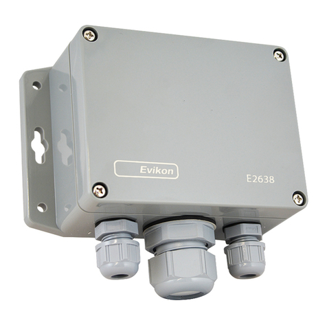
Evikon
Evikon PluraSens E2638 Series user manual
blukii
blukii Smart Beacon Go Mini manual
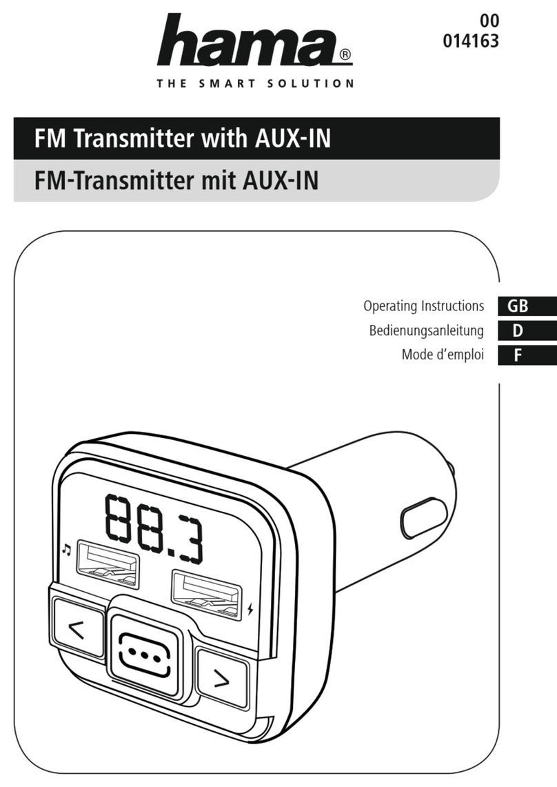
Hama
Hama 00014163 operating instructions
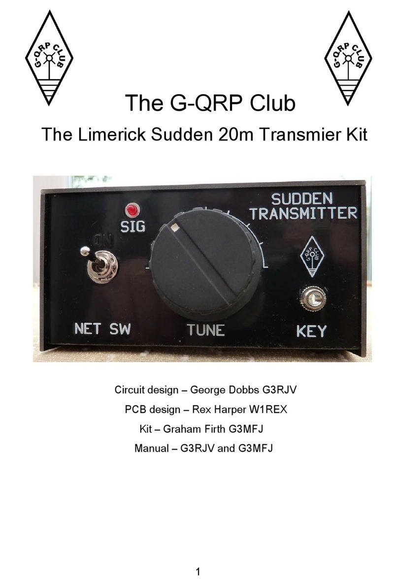
G-QRP Club
G-QRP Club Limerick Sudden manual
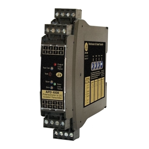
Absolute Process Instruments
Absolute Process Instruments APD 4008 quick start guide

JAROLIFT
JAROLIFT TDRCT-04 operating instructions
