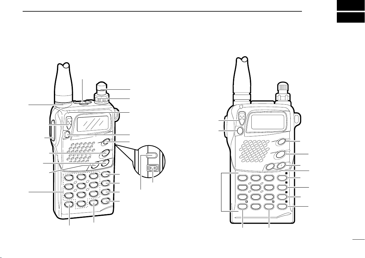
Icom IC-T7H User manual

This device complies with Part 15 of the FCC rules. Operation is sub-
ject to the following two conditions: (1) This device may not cause
harmful interference, and (2) this device must accept any interference
received, including interference that may cause undesired operation.
DUAL BAND FM TRANSCEIVER
iT7H
INSTRUCTION MANUAL
IC-T7H-2.qxd 2007.07.19 4:10 PM Page A

RWARNING! NEVER hold the transceiver so that
the antenna is very close to, or touching exposed parts of the
body, especially the face or eyes, while transmitting. The
transceiver will perform best if the microphone is 5 to 10 cm
(2 to 4 in) away from the lips and the transceiver is vertical.
RWARNING! NEVER operate the transceiver with a
headset or other audio accessories at high volume levels.
Hearing experts advise against continuous high volume
operation. If you experience a ringing in your ears, reduce
the volume level or discontinue use.
NEVER connect the transceiver to an AC outlet or to a
power source of more than 16 V DC. Such a connection will
damage the transceiver.
NEVER connect the transceiver to a power source that is DC
fused at more than 5 A. Accidental reverse connection will be
protected by this fuse, higher fuse values will not give any pro-
tection against such accidents and the transceiver will be ruined.
NEVER attempt to charge alkaline or dry cell batteries.
Beware that external DC power connections will charge bat-
teries inside the battery case. This will damage not only the
battery case but also the transceiver.
i
IMPORTANT
READ ALL INSTRUCTIONS carefully and completely before
using the transceiver.
SAVE THIS INSTRUCTION MANUAL—This instruction man-
ual contains important operating instructions for the IC-T7H.
EXPLICIT DEFINITIONS
The explicit definitions below apply to this instruction manual.
CAUTIONS
The IC-T7H complies with essential requirements of the
89/336/EEC directive for Electromagnetic Compatibility.
This compliance is based on conformity with the ETSI
specification ETS300 684 (EMC product standard for
Commercially Available Amateur Radio Equipment).
WORD DEFINITION
RWARNING Personal injury, fire hazard or electric
shock may occur.
CAUTION Equipment damage may occur.
NOTE If disregarded, inconvenience only. No risk
of personal injury, fire or electric shock.
IC-T7H-2.qxd 2007.07.19 4:10 PM Page i

ii
UNPACKING
Accessories included with the transceiver: Qty.
qAntenna............................................................................1
wHandstrap ........................................................................1
eBattery pack (BP-173/BP-180) or battery case (BP-170)
attached to the transceiver ..............................................1
rBelt clip ............................................................................1
tWall charger*....................................................................1
*Not supplied with battery case versions.
Antenna for U.S.A. version differs from that shown above.
DO NOT push the PTT when not actually desiring to
transmit.
DO NOT operate the transceiver near unshielded electri-
cal blasting caps or in an explosive atmosphere.
AVOID using or placing the transceiver in direct sunlight or
in areas with temperatures below –10°C (+14°F) or above
+60°C (+140°F).
Place unit in a secure place to avoid inadvertent use by chil-
dren.
The use of non-Icom battery packs/chargers may impair
transceiver performance and invalidate the warranty.
Even when the transceiver power is OFF, a slight current still
flows in the circuits. Remove the battery pack or case from
the transceiver when not using it for a long time. Otherwise,
the battery pack or installed dry cell batteries will become
exhausted.
For U.S.A. only
CAUTION: Changes or modifications to this device, not
expressly approved by Icom Inc., could void your authority to
operate this device under FCC regulations.
➀
➁➂➃
➄
IC-T7H-2.qxd 2007.07.19 4:10 PM Page ii

TABLE OF CONTENTS
iii
IMPORTANT ........................................................................ i
EXPLICIT DEFINITIONS ..................................................... i
CAUTIONS .......................................................................... i
UNPACKING ....................................................................... ii
TABLE OF CONTENTS ..................................................... iii
1 PANEL DESCRIPTION ........................................... 1 – 5
■Switches, controls, keys and connectors ................... 1
■Function display ......................................................... 5
2 BATTERY PACKS AND ACCESSORIES ............... 6 – 9
■Battery pack charging ................................................ 6
■Charging precautions ................................................. 6
■About the battery pack ............................................... 6
■Charging connections ................................................ 7
■Battery case ............................................................... 8
■Accessory attachment ................................................ 9
3 BASIC OPERATION ............................................ 10 – 14
■Power ON ................................................................. 10
■Setting a frequency .................................................. 10
■Setting tuning steps .................................................. 11
■Selecting a memory channel .................................... 12
■Lock function ............................................................ 12
■Receive and transmit ............................................... 12
■Repeater operation .................................................. 13
4 ADVANCED FUNCTIONS ................................... 15 – 22
■Memory/call channels .............................................. 15
■DTMF memory operation ......................................... 17
■Scan operation ......................................................... 18
■Subaudible tone operation ....................................... 21
5 OTHER FUNCTIONS .......................................... 23 – 26
■Initial set mode ......................................................... 23
■Channel indication mode ......................................... 26
■CPU resetting ........................................................... 26
6 TROUBLESHOOTING ................................................ 27
7 OPTIONS ..................................................................... 28
8 SPECIFICATIONS ....................................................... 29
9 MODE ARRANGEMENT ..................................... 30 – 31
IC-T7H-2.qxd 2007.07.19 4:10 PM Page iii

PANEL DESCRIPTION 1
1
q[PTT]
!0 [BAND]
!1 [H/L]
!2 [TONE]
!9 @0 [DC13.5V]
y[VOL]
o[POWER]
u[RX/TX]
w[LOCK]
i[MONI]
r[SP/MIC]
e
t[DIAL]
!3
!4
!5
!6
!7
!8
@1
CLR MHz
SKIP
MW
VFO
MR
CALL
S.MW
A
B
C
D
DTMF•M
.
T SCAN
POWER
SCAN
DUP SET
BAND
TONE
HL
LOCK
MONI
w
i
o
!0
!1
!2
!3
!4
!5
!6
!7!8
!9
■Switches, controls, keys and connectors
IC-T7H-2.qxd 2007.07.19 4:10 PM Page 1

1PANEL DESCRIPTION
2
yVOLUME CONTROL [VOL]
Rotate [VOL] clockwise to increase volume and counter-
clockwise to decrease volume.
uRX/TX INDICATOR [RX/TX] (p. 12)
Lights green while receiving a signal or when the squelch
is open; lights red while transmitting.
iMONITOR SWITCH [MONI] (p. 12)
➥Push and hold this switch to force the squelch
open; release to close it again.
➥Push twice to keep the squelch open; push
again to close it.
➥While pushing this switch, rotate [DIAL] to set
the squelch level.
➥While pushing [PTT], push this switch to transmit
a DTMF memory.
oPOWER SWITCH [POWER]
Push for 1 sec. to toggle power ON and OFF.
• Battery voltage appears for 1 sec. after power ON.
!0 BAND SWITCH [BAND/SCAN]
➥Push to toggle between VHF and UHF operation
except in memory mode (p. 10).
➥Push and hold to indicate the selected scan
range (or band) and to start scanning (p. 18).
• While scanning, each push of this switch changes the
selected scan range.
SCAN
BAND
POWER
MONI
qPTT SWITCH [PTT] (p. 12)
Push and hold to transmit; release to receive.
wLOCK SWITCH [LOCK]
Slide up to turn the lock function ON.
• [PTT], [VOL], [H/L], [MONI] and [POWER] function even
when the lock function is activated.
eANTENNA CONNECTOR (p. 9)
Connects the supplied antenna.
rEXTERNAL SPEAKER AND MICROPHONE JACKS
[SP/MIC]
Connect an optional speaker-microphone or headset, if
desired. The internal microphone and speaker will not
function when either is connected. (See p. 28 for options.)
DExternal connection
tTUNING DIAL [DIAL]
Rotate [DIAL] to set an operating frequency, select a mem-
ory channel, select set mode contents, change scan direc-
tion, etc.
This connection
does not apply
when a conden-
sor microphone
is connected.
Remote Audio out
(8 Ω)
[SP]
MIC
3.5 V
PTT
[MIC] Audio input
PTT
33 kΩ
(2 kΩ)
IC-T7H-2.qxd 2007.07.19 4:10 PM Page 2

1
PANEL DESCRIPTION
3
!1 OUTPUT POWER SWITCH [H/L(SET)]
➥Push to toggle between low and high output
power (p. 12).
• “LOW” appears when low output power is selected.
➥Push and hold to enter set mode.
!2 TONE SWITCH [TONE(DUP)]
➥Push this switch to activate the following func-
tions in order (pgs. 21, 22).
• Subaudible tone encoder—“T” appears.
• Pocket beep—“T SQLS” appears.
• Tone squelch—
“T SQL” appears.
• No tone operation—no indicator appears.
➥Push this switch for 1 sec. to select semi-duplex
or simplex operation (p. 13).
• “– DUP” appears during minus duplex operation,
“DUP” appears during plus duplex operation and no
indicator appears during simplex operation.
➥For the European version only, while pushing
[PTT], push this switch to transmit a 1750 Hz
tone burst signal (p. 13).
!3 VFO/CLEAR KEY [VFO(CLR MHz);;]
➥Clears some functions, such as digit input before
entry, scan, etc.
➥Push this key to select VFO mode (p. 10).
➥Push and hold for 1 sec., then rotate [DIAL] to
change the MHz digit (p. 11).
➥While pushing [PTT], this key sends a DTMF “A.”
CLR MHz
VFO
A
DUP
TONE
SET
H L
!4 MEMORY MODE KEY [MR(SKIP)<<]
➥Push this key to select memory mode (p. 12).
•“
XX” appears while in memory mode.
➥While in memory mode, push this key for 1 sec.
to toggle the selected memory channel between
a skip and a non-skip channel (p. 20).
• “SKIP” appears when the channel is set as a skip
channel.
➥While pushing [PTT], this key sends a DTMF “B.”
!5 CALL MODE KEY [CALL==]
➥Push this key to select the call channel (p. 15).
• “C” appears while the call channel is selected.
➥While pushing [PTT], this key sends a DTMF “C.”
!6 SELECT MEMORY WRITE KEY [S.MW(MW)>>]
(pgs. 15, 16)
➥Push this key to enter memory select mode.
•“X” flashes and the [DIAL] can be used for channel
selection (for memory writing or clearing).
➥Push and hold for 1 sec. to write the set contents
into the selected memory channel (or VFO, call
channel).
➥Push then push and hold this key while in mem-
ory select mode to erase the contents of the
selected memory channel.
➥While pushing [PTT], this key sends a DTMF “D.”
MW
S.MW
D
CALL
C
SKIP
MR
B
IC-T7H-2.qxd 2007.07.19 4:10 PM Page 3

1PANEL DESCRIPTION
4
!7 TONE SCAN KEY [TSCAN?]
➥Push this key for 1 sec. to start and stop tone
decode scan (p. 13).
• When a subaudible tone is detected, the tone fre-
quency is displayed and overwrites the prepro-
grammed:
➠tone squelch frequency when the tone squelch is
in use;
➠tone encoder (repeater tone) frequency when the
tone squelch is not in use.
➥While pushing [PTT], this key sends a DTMF “#.”
!8 DTMF KEY [• (DTMF M@)]
➥Enters a decimal for MHz unit during frequency
input (p. 10).
➥Push and hold for 1 sec. to enter DTMF memo-
ry mode for programming or recall (p. 17).
• To program use [(H/L)SET].
• To transmit use [MONI] while transmitting.
➥While pushing [PTT], this key sends a DTMF
“M.”
!9 DIGIT KEYS
➥Input the specified digit during frequency input, memo-
ry channel selection, etc.
➥Transmit the DTMF code of the specified digit while
pushing [PTT].
DTMF•M
.
T SCAN
@0 EXTERNAL DC POWER JACK [DC13.5V]
Allows operation with a 4.5 to 16 V DC power source using
the optional cables, CP-12L or OPC-254L.
CAUTION: Operation with an external DC power
source simultaneously charges batteries inside the
battery case or the battery pack. When using dry cell
batteries this may cause battery leakage and damage
the transceiver; when using a Ni-Cd battery pack this
may cause battery overcharging and shorten the life of
the battery pack.
@1 BATTERY PACK RELEASE (p. 8)
Push to open the latch for battery pack removal.
IC-T7H-2.qxd 2007.07.19 4:10 PM Page 4

5
1
PANEL DESCRIPTION
tMEMORY CHANNEL INDICATOR (p. 12)
Indicates the selected memory channel and other items
such as the call channel, key lock indicator, etc.
yS/RF INDICATORS (p. 12)
Show the relative signal strength while receiving.
and the output power selection while transmitting.
uLOW POWER INDICATOR (p. 12)
Appears when low output power is selected.
iALPHANUMERIC READOUTS
Show the selected frequency, set mode contents, etc.
D
LOW
UP T SQL SKIP
qw e
r
t
yu
i
■Function display
qDUPLEX INDICATORS (p. 13)
Appear during semi-duplex operation.
• “– DUP” appears for minus duplex; “DUP” only appears for plus
duplex.
wTONE INDICATORS (p. 21)
“T” appears when the subaudible tone encoder is in use,
“T SQLS” appears during pocket beep operation and
“T SQL” appears when the tone squelch function is acti-
vated.
eSKIP INDICATOR (p. 20)
Appears when a selected memory channel is set as a skip
channel.
rMEMORY MODE INDICATOR (p. 15)
Appears while in memory mode.
IC-T7H-2.qxd 2007.07.19 4:10 PM Page 5

6
BATTERY PACKS AND ACCESSORIES
2
■Battery pack charging
The supplied* BP-180
BATTERY PACK
includes rechargeable
Ni-Cd batteries and can be charged approx. 300 times.
Charge the battery pack before first operating the transceiv-
er or when the battery pack becomes exhausted.
*Optional for versions which come with the BP-170
BATTERY CASE
.
If you want to be able to charge the battery pack more than
300 times, the following points should be observed:
1. Avoid overcharging. The charging period should be less
than 48 hours.
2. Use the battery until it becomes almost completely
exhausted under normal conditions. We recommend bat-
tery charging just after transmitting becomes impossible.
■Charging precautions
NEVER attempt to charge dry cell batteries. This will cause
internal liquid leakage and damage the battery case and
transceiver.
NEVER connect two or more chargers at the same time.
Charging may not occur under temperatures of 10°C (50°F)
or over temperatures of 40°C (104°F).
■About the battery pack
DOperating period
Depending on the attached battery pack, the operating peri-
od of the transceiver varies. Refer to p. 28 for battery pack
specifications.
DBattery pack life
If your battery pack seems to have no capacity even after
being fully charged, completely discharge it by leaving the
power ON overnight. Then, fully charge the battery pack
again.
If the battery pack still does not retain a charge (or very little),
a new battery pack must be purchased.
Recycling information (U.S.A. only)
The product that you purchased contains a
rechargeable battery. The battery is recyclable. At
the end of its useful life, under various state and local laws,
it may be illegal to dispose of this battery into the municipal
waste stream. Call 1-800-8-BATTERY for battery recycling
options in your area or contact your dealer.
RBRC
RBRC
Ni-
Cd
IC-T7H-2.qxd 2007.07.19 4:10 PM Page 6

7
2
BATTERY PACKS AND ACCESSORIES
■Charging connections
DRegular charging
Attach the supplied* or optional battery pack; then, connect
the supplied* wall charger via an AC outlet as shown below.
*Optional for versions which include a battery case.
DRapid charging with the BC-119
➀Insert the AD-56A into the charging slot of the BC-119.
➁Insert the AD-56B into the groove in the AD-56A (front-fac-
ing side of the AD-56A).
➂Insert the battery pack, either by itself or attached to the
transceiver, into the AD-56B.
To [DC13.5V]
Wall charger
BP-171 or
BP-172
attached to
the transceiver
Check orientation
for correct
charging
BP-171 or
BP-172
WITHOUT
transceiver
BP-173 or
BP-180
WITH
or WITHOUT
transceiver
AD-56
(optional)
BC-119
(optional)
Charging periods:
1 hour (w/BP-171
or BP-180)
1.5 hours (w/BP-172 or BP-173)
Charging periods:
15 hours (w/BP-171, BP-173 or BP-180)
20 hours (w/BP-172)
IC-T7H-2.qxd 2007.07.19 4:10 PM Page 7

8
2BATTERY PACKS AND ACCESSORIES
DOperation with an optional cable
Connect an optional charger or cable to the transceiver as
illustrated below. Be careful of battery overcharging as the
connected battery is charged simultaneously.
■Battery case
When using a battery case attached to the transceiver, install
LR6 (AA) size ×4 alkaline cells as illustrated below.
CAUTION: Remove dry cell batteries when the BP-170
BATTERY CASE
is connected, otherwise the battery may
leak and damage the transceiver.
Open the case.
Remove the case
from the transceiver.
Install LR6 (AA) size
×
4
dry cells into the battery
case.
CP-12L
(optional)
OPC-254L
(optional)
To a cigarette
lighter socket
To a 4.5 to 16* V DC
power source
To
[DC13.5V]
white
black
*To charge the battery pack
12 to 16 V DC is necessary.
IC-T7H-2.qxd 2007.07.19 4:10 PM Page 8

9
2
BATTERY PACKS AND ACCESSORIES
DAntenna
Insert the supplied antenna into the
antenna connector and rotate the anten-
na as shown in the diagram below.
Keep the jack cover attached when
jacks are not in use to avoid bad con-
tacts.
DBelt clip
Remove screws, then attach the belt clip
using the same screws. Conveniently at-
taches to your belt.
DHandstrap
Attach the handstrap as shown in the
diagram below. Facilitates carrying.
■Accessory attachment
CAUTION:
Transmitting without
the antenna may
damage the trans-
ceiver.
IC-T7H-2.qxd 2007.07.19 4:10 PM Page 9

10
3BASIC OPERATION
■Power ON
Push and hold [POWER]
for 1 sec. to turn power
ON.
• Current battery voltage is
displayed for 2 sec.
• The display shows the approx. volt-
age in 0.5 V steps.
• When the battery voltage is lower
than 4.5 V, “LOW V” appears.
Charge the battery in this case.
• If “OVER V” appears, UNPLUG the
external DC plug immediately.
Connected voltage is over 16 V and
could damage the transceiver.
■Setting a frequency
DVia the keypad
(within a band)
➀Push [VFO] to select VFO
mode.
➁Push [BAND] to select the
VHF or UHF band.
➂Push 4 digit keys, starting
from the 1 MHz digit and
including the decimal point
[•], to input a frequency.
• When a digit is mistakenly
input, push [VFO] and input
from the beginning.
•
“0,” “2,” “5” and “7” are accept-
able for the 1 kHz digits
(depending on the 10 kHz digit).
➃To change the frequency
from the 100 kHz digit, push
[•], then 3 digits.
for 1 sec.
after 2 sec.
POWER
3
6
5
5
0
0
0
.
.
Push for
1 sec.
IC-T7H-2.qxd 2007.07.19 4:10 PM Page 10

3
BASIC OPERATION
11
■
Setting tuning steps
This transceiver has 8 tuning steps (VHF and UHF bands
have independent settings) as follows:
• 5 kHz • 10 kHz • 12.5 kHz • 15 kHz
• 20 kHz • 25 kHz • 30 kHz • 50 kHz
➀Push [VFO] to select VFO mode.
➁Push [BAND] to select the VHF or UHF band.
➂Push [(H/L)SET] for 1 sec. to enter set mode.
➃Push [TONE] or [H/L] several times until “TS” appears.
➄Rotate [DIAL] to select the desired tuning step.
➅Push [(VFO)CLR] to exit set mode.
For convenience, select a tuning step that matches the fre-
quency intervals of repeaters in your area.
[DISPLAY EXAMPLE]
15 kHz tuning step 25 kHz tuning step
USING
SET MODE
DVia the keypad
(other band directly)
➀Push [VFO] to select VFO
mode.
➁Push 6 digit keys, starting
from the 100 MHz digit.
• The operating band changes
automatically.
• It’s not necessary to input the
decimal point.
DOther methods
➥VIA THE DIAL: Rotate [DIAL] to change the frequency
according to the set tuning steps.
➥USING THE MHz STEP: Push [(VFO)MHz] for 1 sec., then
rotate [DIAL] to change the frequency in one MHz steps.
0
0
0
0
4
4
IC-T7H-2.qxd 2007.07.19 4:10 PM Page 11

■
Receive and transmit
➀Push [POWER] for 1 sec. to turn power ON.
➁Adjust the [VOL] control to the desired level.
• While pushing [MONI], rotate [VOL].
➂Set the squelch level.
• While pushing [MONI], rotate [DIAL].
• 4 selections are available, “OP”
(open), “AT” (automatic), 1 and 2.
➃Set an operating band and frequency.
When a signal is received:
➥Squelch opens and audio is emitted from the speaker.
➥The S/RF indicator shows the relative signal strength.
➄Push [H/L] to toggle output power between high and low.
• “LOW” appears when low output power is selected.
➅Push and hold [PTT] to transmit; then speak into the mic.
•Do not hold the microphone too close to your mouth or speak
too loudly. This may distort the signal.
• The TX/RX indicator lights red.
• The S/RF indicator shows the output power selection.
➆Release [PTT] to return to receive.
✔CONVENIENT
Monitor function: Push and hold [MONI] to listen to weak
signals that do not open the squelch; or push [MONI] twice to
monitor a signal without having to continuously hold [MONI].
Squelch control: The transceiver employs a noise pulse
count system and therefore, squelch is adjusted automatical-
ly, when “AT” is selected.
12
3BASIC OPERATION
■Selecting a memory channel
➀Push [MR] to select memory
mode.
➁Push 2 digit keys to select
the desired memory chan-
nel (or rotate [DIAL]).
• The first nine memory chan-
nels are preceded by a “0.”
• To select scan edges 1A to 4B,
use [@] for “A” and [?] for “B.”
• Only programmed memory
channels can be selected.
■Lock function
The lock function prevents accidental frequency changes
and accidental function activation.
➥Slide [LOCK] up or down to set the
lock function ON or OFF, respec-
tively.
• “L” appears while the lock function is activated.
• [PTT], [POWER], [VOL], [MONI], and [H/L] can be used regard-
less of this setting.
MR
MR
MR
MR
6
0
IC-T7H-2.qxd 2007.07.19 4:10 PM Page 12

3
BASIC OPERATION
13
■Repeater operation
DGeneral
When using a repeater, the transmit frequency is shifted from
the receive frequency by the offset frequency. It is convenient
to program repeater information into memory channels
(p. 15).
➀Set the operating band and receive frequency (repeater
output frequency).
➁Push [(TONE)DUP] for 1 sec. once to select – DUP or twice
to select DUP.
• “– DUP” or “DUP” appears to indicate the transmit frequency for
minus shift or plus shift, respectively.
• When the auto repeater function is in use (U.S.A. version only)
this selection and step ➂are not necessary (p. 24).
➂Push [TONE] to activate the subaudible tone encoder,
according to repeater requirements.
• “T” appears.
• Refer to the table of tone frequencies on the following page.
➃Push and hold [PTT] to transmit.
• The displayed frequency automatically changes to the transmit
frequency (repeater input frequency).
• If “OFF” appears, check the offset frequency (p. 14).
➄Release [PTT] to receive.
➅Push and hold [MONI] to check whether the other station’s
transmit signal can be directly received or not.
DTone information
Some repeaters require a tone to be accessed. In this case,
precede step ➃at left with the required tone.
DTMF TONES (U.S.A. and Asia versions only)
While pushing [PTT], push the desired digit key(s) to transmit
DTMF tones
• The transceiver has 9 DTMF memory channels. See p. 17 for
details.
1750 Hz TONE (Europe and Italy versions only)
While pushing [PTT], push and hold [TONE] for 1 to 2 sec. to
transmit a 1750 Hz tone signal.
✔CONVENIENT
Tone scan function: When you don’t know the subaudible
tone used for a repeater, the tone scan is convenient for
detecting the tone frequency.
Push and hold [T SCAN?] to activate. See p. 22 for more
information.
IC-T7H-2.qxd 2007.07.19 4:10 PM Page 13

3BASIC OPERATION
14
DSetting subaudible tones for
repeater use
Some repeaters require subaudible tones to be accessed.
Subaudible tones are superimposed over your normal signal
and must be set in advance.
➀
Push [VFO] to select VFO mode.
➁
Push [BAND] to select VHF or UHF.
➂Push [(H/L)SET] for 1 sec. to enter
set mode.
➃Push [TONE] or [H/L] several times
until “rT” appears.
➄Rotate [DIAL] to select the desired
subaudible tone.
➅Push [(VFO)CLR] to exit set mode.
•Available subaudible tone frequencies (unit: Hz)
T
T
USING
SET MODE DSetting an offset frequency
When communicating through a repeater, the transmit fre-
quency is shifted from the receive frequency by an amount
determined by the offset frequency.
➀
Push [VFO] to select VFO mode.
➁
Push [BAND] to select VHF or UHF.
➂Push [(H/L)SET] for 1 sec. to enter
set mode.
➃Push [TONE] or [H/L] several
times until “OW” appears.
➄Rotate [DIAL] to select the desired
offset.
• Selectable steps are the same as the
pre-set tuning steps.
• MHz step may be helpful for large frequency changes—push
[(VFO)MHz] for 1 sec.
➅Push [(VFO)MHz] to exit set mode.
■
Auto low power
When transmitting for 6 continuous min. at high power, the
IC-T7H automatically selects low power. This function cannot
be turned OFF and activates when the power supply is at
approx. 11 V or more. To return to high power on transmit,
select receive, then switch back to transmit.
DUP
DUP
USING
SET MODE
67.0 79.7 94.8 110.9 131.8 156.7 171.3 186.2 203.5 229.1
69.3 82.5 97.4 114.8 136.5 159.8 173.8 189.9 206.5 233.6
71.9 85.4 100.0 118.8 141.3 162.2 177.3 192.8 210.7 241.8
74.4 88.5 103.5 123.0 146.2 165.5 179.9 196.6 218.1 250.3
77.0 91.5 107.2 127.3 151.4 167.9 183.5 199.5 225.7 254.1
IC-T7H-2.qxd 2007.07.19 4:10 PM Page 14

ADVANCED FUNCTIONS 4
15
DProgramming during selection
➀Push [VFO] to select VFO mode.
➁Set the desired frequency:
➥Set other data, such as
repeater information, etc. using
set mode if required.
➂Push [S.MW] momentarily.
•“X” flashes.
• Do not hold [S.MW] for more than 1
sec., otherwise the memory channel
will overwrite the displayed number.
➃Rotate [DIAL] to select the desired
channel.
•
Call channel and scan edge channels,
as well as regular memory channels,
can be programmed in this way.
• If you want to confirm the VFO fre-
quency, push [S.MW] momentarily.
➄Push [S.MW] for 1 sec. to program.
•“X” stops flashing.
D
LOW
UP
D
LOW
UP
D
LOW
UP
D
LOW
UP
MR
MR
■
Memory/call channels
The transceiver has 70 memory channels (60 regular, 4 pairs
of scan edge channels for mixed bands and 1 call channel for
each band). Note that memory channels are not grouped
according to band. In other words, a given memory channel
can be programmed with either a VHF frequency or a UHF
frequency. This is not the case with call channels. Call chan-
nels are band specific.
The following can be programmed into memory/call channels:
• Operating frequency
• Duplex direction with an offset frequency (pgs. 13, 14)
• Subaudible tone encoder or tone squelch ON/OFF with a
tone (CTCSS) frequency (pgs. 21, 22)
• Skip information (p. 20)
IC-T7H-2.qxd 2007.07.19 4:10 PM Page 15

4ADVANCED FUNCTIONS
16
DProgramming after selection
➀Select the memory channel to be programmed:
➥Push [MR] to select memory mode.
➥Rotate [DIAL] (or use the keypad) to select the memo-
ry channel.
• Non-programmed channels cannot be selected.
➁Set the desired frequency in VFO mode:
➥Push [VFO] to select VFO mode.
➥Set the desired frequency using the keypad or [DIAL].
➥Set other data, if desired.
➂Push [S.MW] for 1 sec. to program.
DMemory/call ➾VFO
➀Select the memory/call
channel to be transferred:
➥Push [MR] (or [CALL])
to select memory (call)
mode.
➥Rotate [DIAL] (or use
the keypad) to select
the memory channel.
➁Push [S.MW] for 1 sec. to
transfer to VFO.
DMemory/call ➾call/memory
➀Select the memory/call channel to be transferred:
➥Push [MR] (or [CALL]) to select memory (call) mode.
➥Rotate [DIAL] (or use the keypad) to select the memo-
ry channel.
➁Push [S.MW] momentarily.
• A beep sounds, “VF” appears and “X” flashes.
• Do not hold [S.MW] for more than 1 sec., otherwise the memory
channel will overwrite the VFO.
➂Rotate [DIAL] to select a memory or call channel to trans-
fer the data.
➃Push [S.MW] for 1 sec. to program.
•“X” stops flashing.
DMemory clear
➀Push [S.MW] momentarily.
➁Select the memory channel to be cleared with [DIAL].
➂Push [S.MW] briefly, then a second time for 1 sec.
• 3 beeps sound, then the frequency is cleared.
•“X” flashes continuously.
• Scan edges 1A and 1B and call channels cannot be cleared.
➃Push [(VFO)CLR] to stop the flashing.
NOTE: Be careful — the contents of cleared memories
CANNOT be recalled.
DUP
DUP
VFO mode selected
for
1 sec. Memory mode
MW
S.MW
D
IC-T7H-2.qxd 2007.07.19 4:10 PM Page 16
Other manuals for IC-T7H
2
Table of contents
Other Icom Transceiver manuals

Icom
Icom IC-F3260 Series User manual

Icom
Icom IC-F3162T User manual

Icom
Icom IC-706MKII Owner's manual

Icom
Icom IC-4088SR User manual

Icom
Icom iF3002 User manual

Icom
Icom IC-M505 User manual

Icom
Icom IC-2GXAT User manual

Icom
Icom IC-M1 euro User manual

Icom
Icom IC-22U User manual

Icom
Icom IC-F2000 series User manual