Sonel LKZ-1000 User manual

USER MANUAL
v2.2 4.03.2020
Congratulations on your purchase of a LKZ-1000 instrument
This manual contains important safety directions as well as instructions for setting up the
product and operating it. Refer to "9 Safety Directions" for further information.Read carefully
through the User Manual before you switch on the product.
The serial numbers of your products are indicated on the type plate. nter the serial
numbers in your manual and always refer to this information when you need to contact your
agency or Sonel S.A. authorised service workshop.
Serial No. LKO-1000: _________________________
LKN-1000: _________________________
Conductive Rod: _________________________
Signal Clamp N-2: _________________________
Connection Set AS-1: _________________________
Sonde NAD-1: _________________________
Introduction
Purchase
Product identification
SON L Locator & Transmitter, Introduction
2
SON L Locator & Transmitter, Introduction 3
The symbols used in this manual have the following meanings:
This manual applies to Sonel locator and transmitter instruments LKO-1000 and LKN-1000
and accessories. Differences between the various instruments and models are marked and
described.
Symbols
Validity of this manual
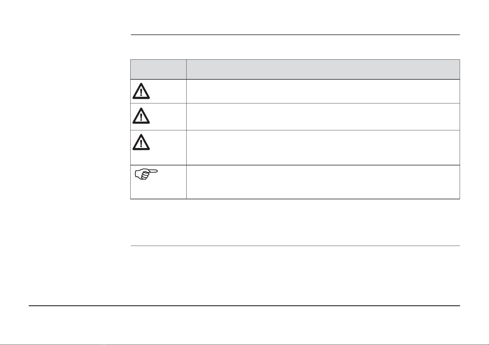
Type Description
Indicates an imminently hazardous situation which, if not avoided, will
result in death or serious injury.
Indicates a potentially hazardous situation or an unintended use which, if
not avoided, could result in death or serious injury.
Indicates a potentially hazardous situation or an unintended use which, if
not avoided, may result in minor or moderate injury and/or appreciable
material, financial and environmental damage.
Important paragraphs which must be adhered to in practice as they enable
the product to be used in a technically correct and efficient manner.
Danger
Warning
Caution

1 General Information 7
1.1 How to Use this Manual 7
1.2 General Information 8
1.3 Instruments and Accessories 10
2 How to Use the Locator 11
2.1 General Information 11
2.2 Locator Overview 12
2.3 Locator Setup and Information 14
2.4 Hazard Zone 16
2.5 How to Locate a Service 18
3 How to Use the Transmitter 30
3.1 General information 30
3.2 Transmitter Overview 31
3.3 How to Locate a Service Using the Transmitter 33
4 How to Use the Conductive Rod 37
4.1 General Information 37
4.2 Conductive Rod Overview 37
4.3 How to Locate a Service Using the Conductive Rod 38
Table of Contents
In this manual
SON L Locator & Transmitter, LKZ-1000
4

SON L Locator & Transmitter, Table of Contents 5
5 How to Use the Signal Clamp 40
5.1 General Information 40
5.2 Signal Clamp Overview 40
5.3 How to Locate a Service Using the Signal Clamp 41
6 How to Use the Property Connection Set 43
6.1 General Information 43
6.2 Property Connection Set Overview 43
6.3 How to Locate a Service Using the Property Connection Set 44
7 How to Use the Sonde 46
7.1 General Information 46
7.2 Sonde Overview 46
7.3 How to Locate a Service Using the Sonde 49
8 Care and Transport 51
8.1 Transport 51
8.2 Storage 51
8.3 Cleaning and Drying 52

9 Technical Data 53
9.1 Locator Technical Data 53
9.2 Transmitter Technical Data 57
9.3 Conductive Rod Technical Data 60
9.4 Sonde Technical Data 62
9.5 Property Connection Set Technical Data 64
9.6 Signal Clamp Technical Data 66
Appendix A Functional Checks 69
A.1 Locator Functional Check 69
A.2 Transmitter Functional Check 73
A.3 Conductive Rod Functional Check 78
A.4 Sonde Functional Check 80
Appendix B World Frequency Zones 83
SON L Locator & Transmitter, LKZ-1000
6
SON L Locator & Transmitter, General Information 7
It is recommended to set up the product while reading through this manual.
The index is at the back of the manual.
On the Locator and Transmitter you will find a label that shows some important information
by means of illustrations. You will find some of these illustrations in this manual too. This
should help to get a clear connection between the instrument label and the informa-tion in
this manual.
1. General Information
1.1 How to use this manual
Index
Instrument label

Locators are used to detect buried conductive services emitting an electromagnetic signal
which is generated by a current passing through the service.
Transmitters are used to apply a distinct signal to conductive services, which may not radiate
electromagnetic signals or may need to be traced for a specific purpose.The Transmitter is
required to make a depth measurement.
The Locators and Transmitters described within this manual will greatly increase the detec-
tion process and help to reduce the dangers and costs associated with service strikes. But
the very nature of electromagnetic location is dependent on the services being conductive
(metallic) and radiating a signal as current flows through them.
It is important to remember that a Locator on its own will not detect all services and care
should be taken when excavating. It is generally accepted that a safe system of work should
be adopted which would include planning the work in advance, the use of utility maps, the
use of Locators and Transmitters, and the use of safe digging practices.
The absence of a positive indication does not guarantee the non-existence of a service.
Services without a detectable signal may be present.
The Locators can only locate non-metallic services such as plastic pipes, typically used by
the water and gas utilities, with the use of appropriate accessories.
Precautions:
Always excavate with care.
1.2 Sonel - General Information
Description
Caution
SON L Locator & Transmitter, LKZ-1000
8

SON L Locator & Transmitter, General Information 9
Designed to increase the detection of services with no (or little) signals on them. Generally
work in conjunction with the Locator and Transmitter.
Designed to demonstrate the equipment is working satisfactorily in between service
intervals. Refer to "Appendix A Functional Checks" for more information.
Accessories
Functional Check
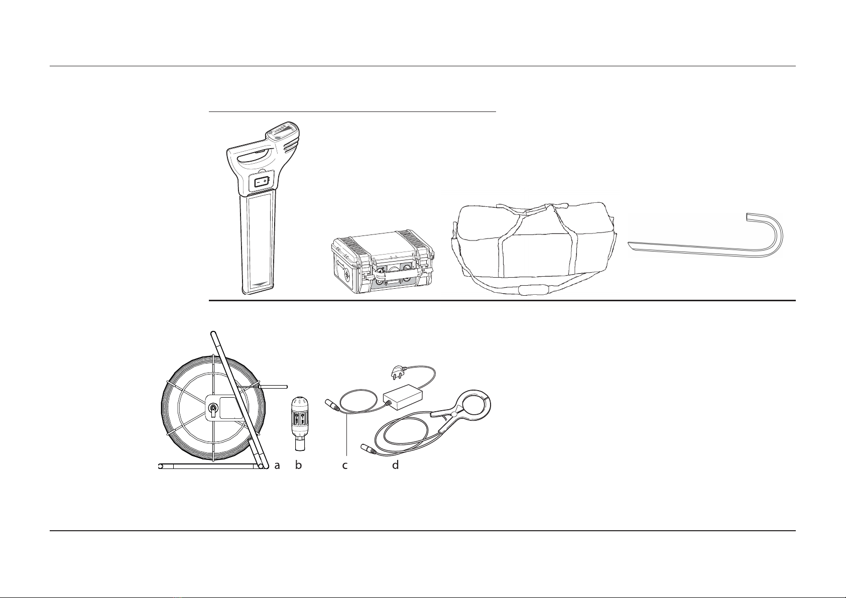
1.3 Instruments and Accessories
General information
Instruments Overview
Accessories Overview a) Conductive Rod (non metallic service tracer):
-30m (WAPRZPN30)
-50m (WAPRZPN50)
-80m (WAPRZPN80)
b) Sonde NAD-1 (WASONNAD1)
c) Property Connection Set AS-1
urope („French”) standard(WAADAAS1P )
Switzerland standard (WAADAAS1CH)
US standard (WAADAAS1US)
Australia standard (WAADAAS1AU)
d) Signal Clamp N-2 (WACEGN2)
This is a collection of products used to locate
buried metallic and nonmetallic services.
SON L Locator & Transmitter, LKZ-1000
10
a) Locator LKO-1000
b) Transmitter LKN-1000
c) Case L-6
d) Earth contact pin probe
(WMGB KO1000)
(WMGB KN1000)
(WAFUT 6)
(WASONG15)
c
F
i
a b d

SON L Locator & Transmitter, How to Use the Locator 11
• Passive modes (Power and Radio)
• Active modes (8kHz and 33kHz)
• Auto mode (Combined Power and Radio modes)
An electromagnetic signal radiates from buried conductive services as an electrical current flows
through them. The Locator processes these signals and displays their presence.
Some signals are already present on buried services and can be readily detected by the
Locator. We call these passive signals. These signals are generated by power distribution
systems and radio transmitters.
Some conductive services do not emit passive signals. These services may be traced by
applying a signal to the service by using a transmitter.
Depth indication is only available with the Locator when used in conjunction with the Transmitter
or Sonde. The displayed depth is to the centre of the service or to the Sonde.
Provides an additional alarm, indicating the close proximity of a service emitting a Power, 8kHz
or 33kHz signal.
Assists in pinpointing a service by displaying the peak reading for a short period of time.
2. How to Use the ocator
2.1 General Information
Operating Modes
Electromagnetic signals
Passive signals
Active tracing
Depth indication
Hazard zone
Peak hold

2.2 KO-1000 ocator Overview
ocator main parts a) Display Panel
Contains the operational controls.
b) Speakers (mounted internally left and right)
Active at power on and when a signal is detected.
c) On/Off Trigger
Press and hold the trigger to activate the Locator.
Release the trigger to deactivate.
d) Battery Hatch Release
Pressing the yellow release button unlocks the battery
hatch allowing access to the battery compartment.
e) Battery Compartment
6 x LR6 (AA) alkaline batteries are used. Replace all
batteries when indicated.
f) Case Foot
The case foot can be replaced if it is worn. Contact your agency or Sonel S.A. authorised
service workshop.
SON L Locator & Transmitter, LKZ-1000
12
SONEL Locator &Transmitter, How to Use the Locator 13
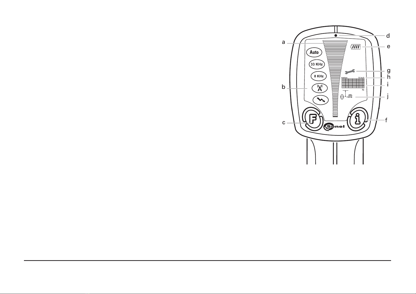
Display panel overview
a) Signal Strength Indicator
Indicates the response of the Locator to a signal (service).
b) Mode Indicators
Displays the selected mode: Power, Radio, 8kHz, 33kHz, Auto (as shown, from bottom
to top).
c) Function Button
Selects operating mode.
d) Light Sensor
Automatically switches the displays backlight on or off to suit light conditions.
e) Battery Indicator
Indicates the battery condition. Segment illumina-tion decreases as battery condition
declines. Replace the batteries when the battery indicator is empty.
f) „i” Button
Used to access the user settings and to provide a depth readout.
g) Wrench
Indicates that the Locator requires periodic service.
h) Measurement Unit
Indicates depth indication is in metric or feet and inches.
i) Display Readout
Alpha numeric matrix indicates system set up and depth indication.
j) Depth Mode Indicators
Indicates a depth reading to a service or a Sonde. Service depth icon used to indicate ‘Hazard Zone’ status.
It is recommended to perform periodic calibration of the device every 12 months.

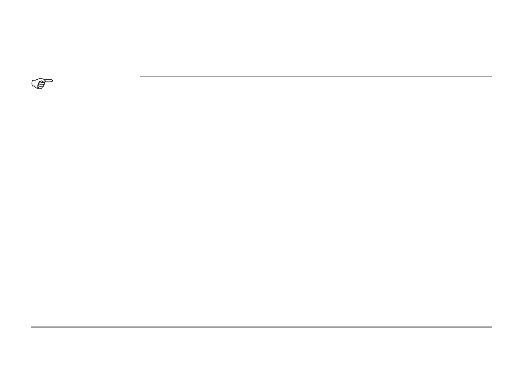
Setting Description
EST Performs a function check on the locators hardware and software, displaying PAS if the
Locator is within predefined tolerance or RR if the locator it is not.
H.Z Switches ‘Hazard Zone’ on or off.
VO Adjust volume level (0 - 10).
H D Adjust peak hold duration (0 - 5 seconds).
SSI Displays a numeric signal strength indicator.
CST Adjusts display’s contrast (0 - 15).
M/I Displays unit of measurement.
CA Displays the next service date DD/MM/YY.
TE Displays supplier/company telephone number.
I.D. Displays the operator’s name.
PWR Displays the power mode regional setting. Refer to "Appendix B World Frequency Zones"
for more information.
SR# Displays unit serial number.
VER Displays software version
C K Displays the date held within the locators memory. Format DD/MM/YY/HH/MM/SS
The Locators offer a range of settings which the operator can adjust to their own preference.
It also displays additional service and contact information as detailed
2.3 ocator Setup and Information
SON L Locator & Transmitter, LKZ-1000
14
SON L Locator & Transmitter, How to Use the Locator 15
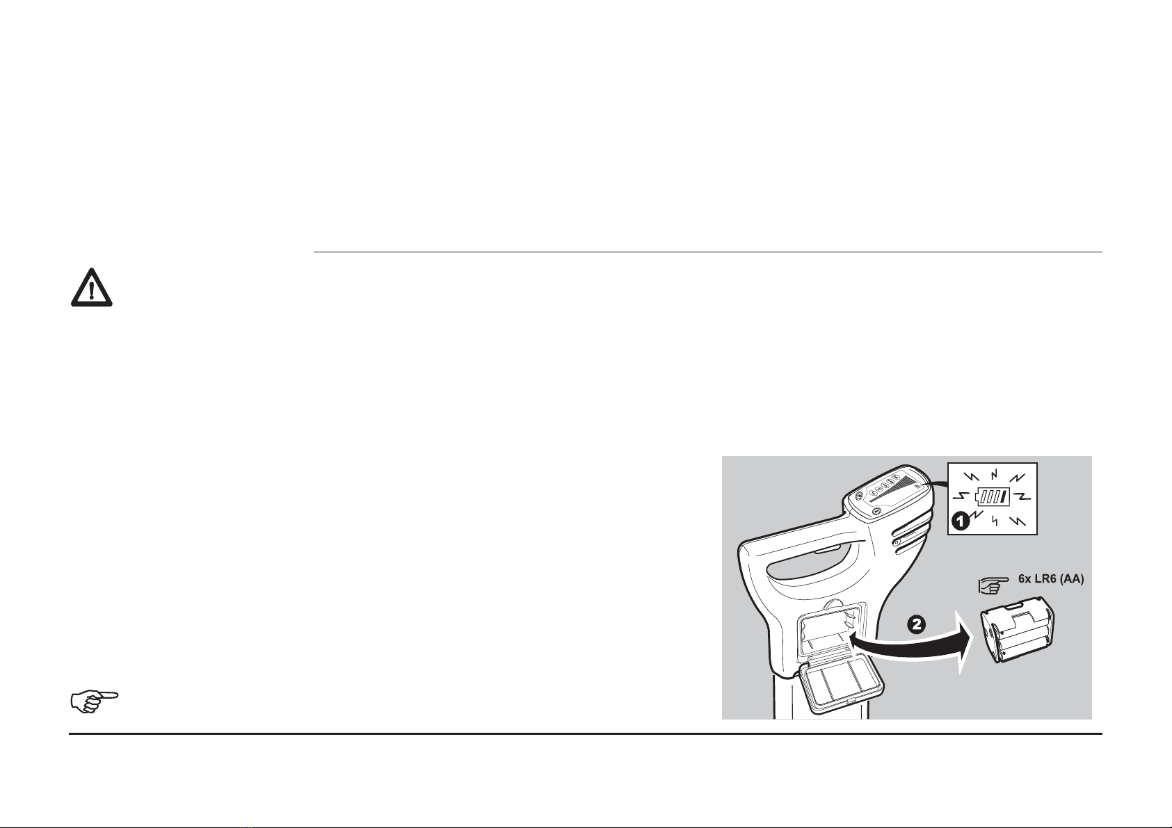
1. Replace or recharge the batteries when
the battery status indicator is empty.
2. Press the release button to unlock the
Battery Hatch. Remove the battery holder
from the Locator.
3. Replace all batteries with six new LR6(AA)
batteries, or remove and recharge the
battery pack if rechargeable batteries are
fitted.
Alkaline batteries should be used.
Accessing and
adjusting the settings
Danger
Changing the battery
F
i
1. Switch the Locator on.
2. nsure the Locator is in Power mode. If required, press Function Button to select mode.
3. Depress „i” Button for 2 seconds. The user settings will be displayed in the display
readout.
4. Press Function Button to toggle through to desired setting.
5. Press „i” Button to select the setting.
6. Press Function Button to activate/adjust.
7. Press „i” Button to store and exit.
The Locator may fail to detect electrical services in Power mode if an incorrect power setting
is used.
Precautions:
Before use, verify the Locator is setup to be compatible with mains frequency supply in your
country. Options are 50 or 60Hz. Refer to Appendix B „World Frequency Zones" for more
information.
Contact your agency or Sonel S.A. authorised service workshop if your unit is incorrectly
configured for your region.

2.4 Hazard Zone
Description
Hazard zone status
indicators
Provides an additional warning to the close proximity of buried services and functions in the
following modes:
• Power
• 8 kHz
• 33 kHz
• Auto mode (Power mode only)
Status Indicator Description
Hazard zone is switched on.
Hazard zone on and is alarming.
Hazard zone is switched off.
SON L Locator & Transmitter, LKZ-1000
16

SON L Locator & Transmitter, How to Use the Locator 17
Caution The absence of a positive indication does not guarantee the non-existence of a service.
Services without a detectable signal may be present. The Locators can only locate non-
metallic services such as plastic pipes, typically used by the water and gas utilities, with the
use of appropriate accessories.
Precautions:
Always excavate with care.

2.5 How to ocate a Service
Start up test
ocating process
The following test sequence will take place every time the Locator is activated.
On test Test pattern Info on label
Audio Output On throughout test
sequence
Signal Strength
indicator
Scrolls through in
sequence once
Mode indicators Briefly illuminated
Battery indicator On throughout
Measurement unit,
display readout, depth
mode indicator
Briefly illuminated
The unit will then go into Power mode maximum sensitivity.
The locating process is split into three steps:
• Sweep Search
• Pinpointing the service
• Direction of the service
SON L Locator & Transmitter, LKZ-1000
18
SON L Locator & Transmitter, How to Use the Locator 19
Sweep Search The unit will automatically select
Power mode and maximum
sensitivity
Auto mode combines the benefit of
simultaneous detection in Power
and Radio modes and helps to
confirm the presence of services
upon initial site occupation.
Improved defi-nition of the service
will be provided by single mode
operation.
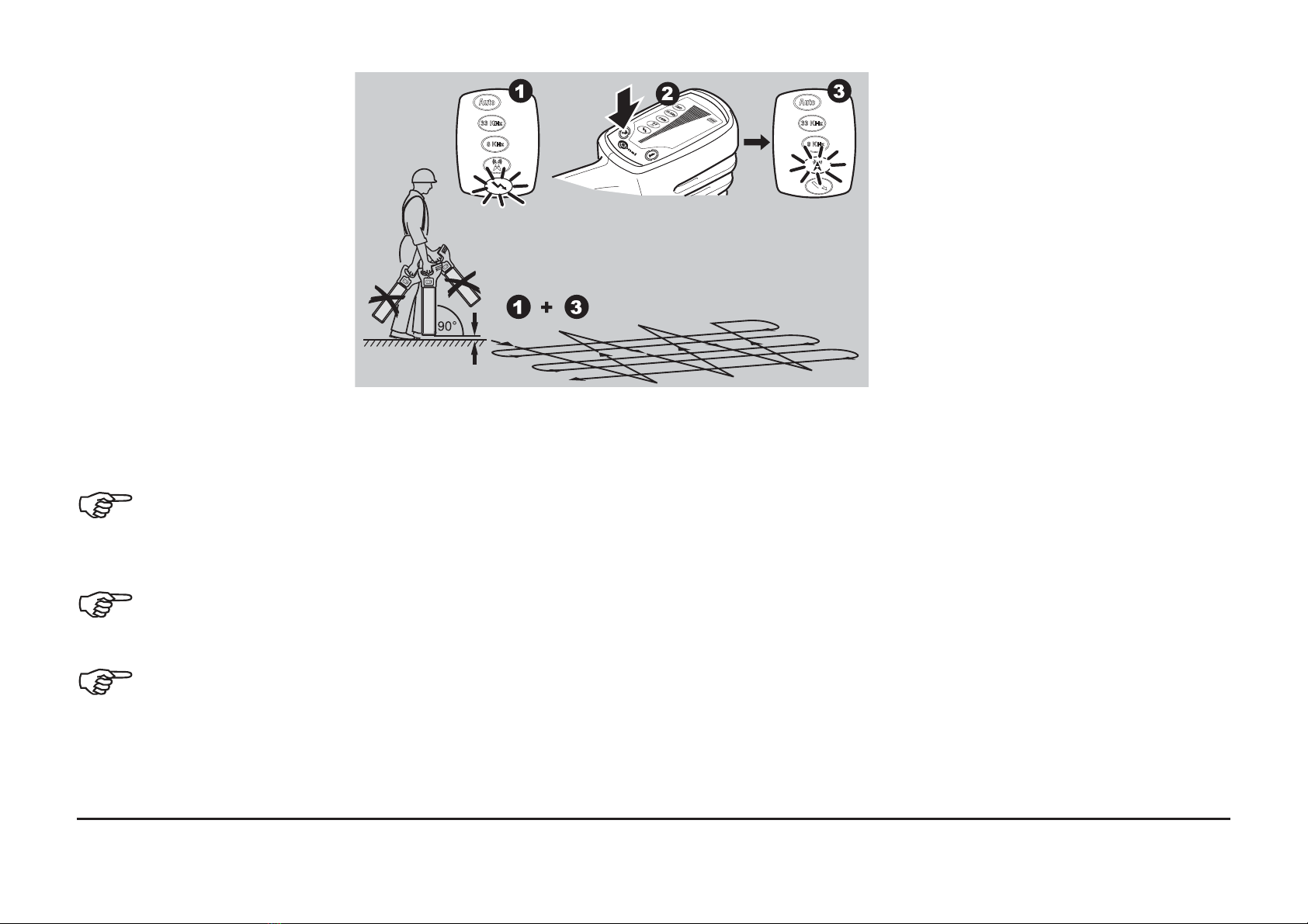
1. Define the area to be excavated.
2. In Power mode cross the site from left to right keeping the Locator LKO-1000 upright,
taking care not to swing the unit. Turn through 90 degrees and repeat.
Ensure that the ocator is held in an upright position and close to the ground.
3. Continue the sweep until either a signal is located or you are satisfied that the area has
been adequately tested.
In the presence of a service emitting a traceable signal a tone will be emitted and
the signal strength indicator will rise and fall as you pass over it.
4. Repeat the Sweep Search process in Radio mode.
The Sweep Search must be conducted in Power and Radio modes as a minimum,
as not all services (including some electrical ones) emit a power signal. These
services may be found using Radio mode or active modes.

Hazard zone can be operated in Power, 8kHz, 33kHz and Auto modes and provides an
additional alarm to the presence of buried services which may be within close proximity.
Retrace your steps to the area
where the highest signal reading
(peak response) was obtained.
The service is directly below the
Locator when the signal strength
indicator is at its maximum. The
audio output will automatically
adjust to facilitate pinpointing over
the service, and automati-cally
reset when the signal strength
indicator drops to its minimum
position.
• Always use chalk or paint to mark services, never pegs.
• The signal strength indicator does not indicate the size, depth or type of a service.
Peak hold
When activated peak hold will show the highest peak reading obtained during the pinpoint
process. The displayed reading can be adjusted between 0 to 5 seconds.
Pinpointing the service
SON L Locator & Transmitter, LKZ-1000
20
Table of contents
Other Sonel Test Equipment manuals


Sonel
Sonel TKF-12 User manual

Sonel
Sonel PAT-806 User manual

Sonel
Sonel S-36 VLF User manual

Sonel
Sonel VT-3 User manual

Sonel
Sonel TKF-12 User manual

Sonel
Sonel PAT-806-IT User manual

Sonel
Sonel P-3 User manual

Sonel
Sonel UV-260 Corona Camera User manual

Sonel
Sonel P-2 User manual

Sonel
Sonel MRP-201 User manual
Popular Test Equipment manuals by other brands


Indutherm
Indutherm VTC800V Documentation

Elma
Elma 2000X instruction manual

Orion Diagnostica
Orion Diagnostica QuikRead iFOB manual

Agilent Technologies
Agilent Technologies E4400-60598 Installation notes

CTB
CTB DO148 Quick start user guide

Leader Electronics Corp.
Leader Electronics Corp. LTC-906 instruction manual