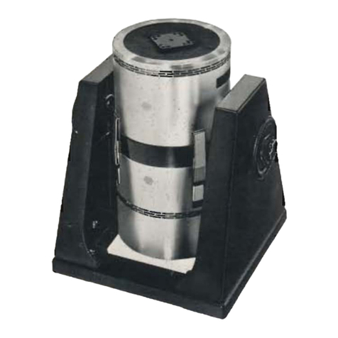
Imada MX-500N Series User manual

INSTRUCTION MANUAL
TEST STAND
MX-500N Series
MV-500NII Series
Before use, read through this instruction manual to use this unit correctly.
Keep this instruction manual as this includes a “Certificate of warranty”
Uploaded by TheGioiCongNghiep.com

Instruction Manual MX-500N / MV-500NII Series
2 Manual No. MXV50801E

Instruction Manual MX-500N / MV-500NII Series
3 Manual No. MXV50801E
INTRODUCTION
Thank you very much for adopting Imada product. MX/MV-500N series is the force
measuring instrument which combines with Imada brand digital force gauge or
mechanical force gauge. It measures tensile and compressive force by motorized
stable speed. Moreover, in case large force is measured, there is no fatigue. Optional
length/speed meter meets the demands for investigation of connection between length
and force.
In order enough to utilize this machine, be sure to read this instruction manual before
use. Please keep it carefully after reading. Although produced and shipped at the
origin of a severe quality control of our company, and inspection, if there is a doubtful
point, if possible, please inform to your local dealer or us.
Cautions of the overload of a force gauge;
No matter if its power supply is ON or OFF, it will be damaged when the force
exceeding tolerance level is applied.
Force gauge will be damaged if its sensing shaft is applied a bending or torsion
force.
Force gauge will be damaged by the force beyond its capacity.
Please follow the instruction manuals of attachment for each product about use of a
force gauge.
Cautions of storage.
Please avoid oil, dust, and heat and high humidity, and keep it in a cool place.
After use, please protect the measuring shaft of a force gauge form load or a shock.
Please do not use organic solvents, such as thinner, for removing the dirt.

Instruction Manual MX-500N / MV-500NII Series
4 Manual No. MXV50801E
Cautions of a force gauge accuracy guarantee.
Although based on operating frequency or load level, the accuracy of a force gauge
deteriorates with time. We recommend you to take it out to periodical check and
proofreading.
In order to carry out more exact measurement, please use it by temperature within
the limits described in the inspection certificate attached with a force gauge.
Please do not disassemble or do not convert the force gauge and test stand.
Cautions on safe.
Please use it after protecting an eye, the body, and this unit, when danger -- boiling
water and a fragment, and a dangerous chemistry substance scatter -- is expected.
Be sure to use an attached adapter to charge the force gauge. If another one than
an attached adapter are used, it may causes, such as failure, a fire, etc. of about that
it becomes impossible to guarantee accuracy and this unit.
Never use this machine for any purposes other than measurement.
“Over load stop”function for MX-500N series does not avoid overload completely.
In addition, please deal with it according to cautions of an instruction manual attached
with a force gauge.

Instruction Manual MX-500N / MV-500NII Series
5 Manual No. MXV50801E
OVERVIEW
Limit knobs
Table
Crosshead
Grip mount GF-1
Operation
panel
Force gauge mount
H(mm)
Model
H
T
MX/MV-500N(-S)
573
285
MX/MV-500N(-S)-L
773
485
MX/MV-500N-E
633
285
MX-MV-500N-E-L
833
485

Instruction Manual MX-500N / MV-500NII Series
6 Manual No. MXV50801E
Dimensions of force gauge mount
Rear view
* EN-00 connector is only for MX-500N-E or MV-500NII-E series
4 holes 4.5 mm dia.
For digital force gauge.
4 holes 3.5 mm dia.
For mechanical force gauge
IO Connector
MV Series
EN-00 Connector
Fuse Case
Inlet
MX Series
MV-E Series
MX-E Series
IO Connector
EN-00 Connector

Instruction Manual MX-500N / MV-500NII Series
7 Manual No. MXV50801E
Operation panel
MX series
MV series
Emergency
button
Power switch
Speed volume
Mode LED
Run LED
FS LED
Up/Down buttons
Mode button
FS button
Run LED
Up/Down Buttons
Emergency
button
Power switch
Speed volume
FS volume

Instruction Manual MX-500N / MV-500NII Series
8 Manual No. MXV50801E
Features
Overview (Page 5)
Limit knobs
Upper / Lower travel limits are …by those knobs. Turning left
to loosen. Tighten after sliding them up or down to any
position.
Crosshead
Goes up or down with force gauge.
Force gauge mount
Mount the force gauge here. There are certain holes suitable
for Imada brand force gauges.
Table
Put a sample here or fix a fixture with GF-1 grip mount.
Rear view (Page 6)
Inlet
Plug power cord (included)
Fuse case
A fuse is in this case
I/O Connector
MX series only
Connect certain force gauge here to use “Force control
mode”through an optional cable CB-501
EN-00 Connector
MX/MV-E series only
Connect a speed / Length meter EN-00 here
Operation panel (Page 7)
Emergency button
Force to stop the test stand by pressing this button for
emergency situation. To release the button, turn it left.
For MX series, you must return the test stand power on to
use it again.
Power switch
Turn on/off the power of the test stand
Speed volume
Adjust travel speed of the crosshead in no-step.
FS volume
Adjust travel speed when you select “Fix speed (FS)”mode.
Seal this hole if you won’t change speed.
FS button
Enable/Disable “Fix speed”mode
Mode button
Select modes
Up/Down buttons
Indicate test stand movement
LEDs
Display current mode and movement

Instruction Manual MX-500N / MV-500NII Series
9 Manual No. MXV50801E
I/O Connector pin assignment
A
-NG signal
B
OK signal
C
+NG signal
D
Overload signal
E
N/C
F
Signals ground
Supplies
Below supplies are included with this unit
GF-1 grip mount
1
Power supply cord
1
Fuse
1
This instruction manual
1
Carton box
1
Allen key for M3
1
Allen key for M4
1
Allen key for M8
1
M3 x 12mm bolts
4
M4 x 8mm bolts
4
MX-500N-E / MV-500NII-E series includes also...
EN-00 Length/Speed meter
1
MX-500N-S / MV-500NII-S series includes also…
Manual for scale unit
1

Instruction Manual MX-500N / MV-500NII Series
10 Manual No. MXV50801E
Specifications
Models
MX-500N Series
MV-500NII Series
Normal
MX-500N
MV-500NII
Speed/Length meter
MX-500N-E
MV-500NII-E
Scale unit
MX-500N-S
MV-500NII-S
Long stroke
MX-500N-L
MV-500NII-L
Long stroke
Speed/Length meter
MX-500N-E-L
MV-500NII-E-L
Long Stroke
Scale unit
MX-500N-S-L
MV-500NII-S-L
Attach the following suffix after model name to specify speed range..
Suffix
Speed range
Capacity
-WF
40 –1200 mm/min
200N
-F
20 –600 mm/min
500N
250N (Long stroke)
-O
2 –60 mm/min
500N
250N (Long stroke)

Instruction Manual MX-500N / MV-500NII Series
11 Manual No. MXV50801E
Specifications
MX-500N series
MV-500NII series
Capacity
500N
250N (Long stroke)
Stroke
Approx. 285mm
Approx. 485mm (Long stroke)
Weight
Approx. 18 kg
Approx. 19kg (Long stroke)
Speed range
10 to 300 mm/min variable (No specified)
Dimensions
See page “OVERVIEW”
Functions
Manual
Single cycle
Continuous cycle
Force control *1
Overload stop*1
Manual
Crosshead runs up and down with motor
Adjustable upper/lower travel
Adjustable speed
Recommended
force gauge
IMADAbrand digital and mechanical force gauges
Except high-capacity models
Options*2
Length/Speed meter: “-E”suffix follows model name
Scale unit: “-S”suffix follows with model name
Long stroke: “-L”suffix follows with model name
*1 Certain models of force gauge are compatible. Optional cable is necessary.
*2 Factory built only.

Instruction Manual MX-500N / MV-500NII Series
12 Manual No. MXV50801E
Mounting force gauge
Mounting digital/mechanical force gauge
1. Unscrew two flap-nuts, and release the force gauge mount with taking care not to slip
the mount down.
2. Tighten force gauge to mount with remaining M6 flat-head screws in the hole.
3. Insert the tip of M6 flat-head screws into the holes on the crosshead. Tighten it by
flap-nuts.
Especially the force gauge of low capacity breaks down according to over load also by
small force. Please pay your attention that an attachment tip does not hit a table.
Force gauge mount
Screws (included)
M6 flat head screws
Flap nuts
Crosshead
Screws (included)
M6 flat head screws

Instruction Manual MX-500N / MV-500NII Series
13 Manual No. MXV50801E
Scale unit (only with MX/MV-500N-S)
A scale unit included with MX/MV-500N-S series can display travel length of the
crosshead so that you can measure elastic character and so on. For details, see an
instruction manual for the scale unit.
Scale unit: Mitutoyo Digimatic scale unit SDV-30E(Normal) SDV-45E(Long stroke)
Scale unit

Instruction Manual MX-500N / MV-500NII Series
14 Manual No. MXV50801E
Length/Speed Meter (only with MX/MV-500N-E)
About…
MX/MV-500N-E series has a built-in rotary-encoder which makes it possible to measure
travel length and speed by sensing rotation of its feed screw. You can see those
measurements with a display unit EN-00 included with.
Connection
After turn off the power of the test stand,
plug it into “EN-00”connecter on the rear
side of the unit.
Operation
After plugging EN-00, turn on the test stand to display length and speed. Press zero
button when the crosshead is at the original position. Speed is always displayed.
Please refer the instruction manual for EN-00 for details.
Never plug or unplug the display unit while the test stand is powered, or it would
cause the display unit failure.
The display unit may not display anything when you turn the test stand on right after
turning the unit off. Please wait at least 3 seconds for turning it on.
Length
Speed
HOLD button:
Holds the display while pressing
Zero button:
Zero the display
Display unit EN-00
Rear view of the test stand
Display unit

Instruction Manual MX-500N / MV-500NII Series
15 Manual No. MXV50801E
Procedures
Screwing attachment(s) If needed, use optional
attachment or standard
attachment mounting on the
sensing shaft of the force gauge.
1. When you attach an
attachment on the table side,
please attach GF-1 on a table.
2. To mount an attachment for
tensile force, use M6 screw
standing on the GF-1 and fix it
at certain angle by a nut.
3. Never use any tool to tighten
an attachment to the sensing
shaft of the force gauge to
prevent it from overload.
Adjusting upper and lower limit
1. Press to select “Manual Operation”
2. Press ( ) to drive crosshead to upper (lower) limit position whether you
want to stop.
3. Loosen upper (lower) limit knob
4. Move limit knob until it touches the crosshead.
5. Tighten limit knob.
Selecting mode (MX)
1. It is “Manual Operation” mode when turn the power on.
2. Whenever pressing , current mode switches in the sequence “Manual
Operation”→”Single cycle”→”Continuous cycle”. LED displays current mode.
Optional attachment
Optional attachment
Sample

Instruction Manual MX-500N / MV-500NII Series
16 Manual No. MXV50801E
Operating MX series
MX-500N series has three operation modes. This unit has “Overload stop”feature that
always works while the gauge is connected by optional cable and it is powered on. Also
“Force control”feature works when the gauge is connected.
The cable to connect between gauge and the test stand is sold separately. Some force
gauge is not compatible with those features
Three modes
Manual mode
Crosshead moves while pressing
Single cycle mode
Crosshead starts by . It will reverse its travel
direction when it reaches travel limit at its maximum speed. It
automatically stops at another travel limit.
Continuous cycle mode
Continuously goes up and down between its upper and lower
travel limit.
Additional mode effective when the gauge is connected
Force control mode
Connecting with the gauge, the crosshead moves according
to the comparator signals (OK/NG) from the gauge.
Stops when above signal shows +OK.
Automatically control the crosshead to keep the
force between high and low comparators setup
values.
Selecting modes`
3. It is in Manual mode when you turn the test stand on.
4. Every pressing selects mode in the sequence of Manual - Single cycle -
Continuous cycle with LED indication.

Instruction Manual MX-500N / MV-500NII Series
17 Manual No. MXV50801E
Operation in Manual mode
1. Select Manual mode by button.
2. Whenever pressing toggles “FS Effective” LED lights up and off. When it is
lights, “Speed knob” is not effective, but the “Fixed speed volume” is. You cannot
toggle FS Effective while the crosshead runs.
3. While pressing the crosshead runs to the direction of button figure at its
maximum speed. It stops when you release the button or when it gets to each limit
knob.
4. While pressing the crosshead runs to the direction of button figure at
the speed indicated by speed volume or FS volume. It stops when you release the
button or when it gets to each limit knob.
Operation in Single cycle mode
1. Select Single cycle mode by button.
2. Whenever pressing toggles “FS Effective” LED lights up and off. When it is
lights, “Speed knob” is not effective, but the “Fixed speed volume” is. You cannot
toggle FS Effective while the crosshead runs.
3. Press and release buttons to start crosshead running to the direction of
button figure at its maximum speed. The crosshead reverses when it gets to the
limit knob at its maximum speed. It stops when it gets to another limit knob.
4. Press and release buttons to start crosshead running to the direction of
button figure at the speed indicated by speed volume or FS volume. When it gets to
each limit knob, it goes reverse direction until getting to another limit knob.

Instruction Manual MX-500N / MV-500NII Series
18 Manual No. MXV50801E
Operation in Continuous cycle mode
1. Select Continuous cycle mode by button.
2. Whenever pressing toggles “FS Effective” LED lights up and off. When it is
lights, “Speed knob” is not effective, but the “Fixed speed volume” is. You cannot
toggle FS Effective while the crosshead runs.
3. Press and release buttons to start crosshead running to the direction of
button figure at its maximum speed. The crosshead reverses when it gets to the
limit knob at its maximum speed. Until pressing some Up/Down button or Mode
button, it keeps up-and-down motion at its maximum speed.
4. Press and release buttons to start crosshead running to the direction of
button figure at the speed indicated by speed volume or FS volume. When it gets to
each limit knob, it goes reverse direction until getting to another limit knob. Until
pressing some Up/Down button or Mode button, it keeps up-and-down motion at
indicated seed.

Instruction Manual MX-500N / MV-500NII Series
19 Manual No. MXV50801E
Operation in Force control mode
MX-500N series combined with Imada brand force gauge connected through an optional
cable (CB-501) can get additional functions as below
Forcing stopping the test stand by “Overload”signal from the force gauge. The
signal is usually output when the applied force is beyond by a several percent of
its capacity. In any operational mode this unit is, “Overload-stop”function
always works while the gauge is connected and powered.
Decrease speed when a signal of comparator is “OK”. Stops when a signal is
“+NG”.
Automatically keeps the force for the comparator signal to be “OK”.
Force gauges corresponding with above features. (as of 2006)
Digital force gauge DPZ and DPZH series
Digital force gauge ZP, Z2, ZPH and Z2H series.
Above feature IS NOT a complete protection for overload, but it is to reduce
risks of damage
In any mode the test stand is, it stops when the gauge outputs an overload
signal.
After overload-stop, the test stand never accepts any operation. Once turn it
off, disconnect a cable, and turn it on again to be operated.
The force gauge may be damaged on its sensing device after overload-stop
works. Please ask your local dealer to be inspected.

Instruction Manual MX-500N / MV-500NII Series
20 Manual No. MXV50801E
1. Setup comparator high and low values of the force gauge. For details, please refer
an instruction manuals included with the gauge.
2. Connect the gauge and the test stand through the cable (CB-501; sold separately),
and turn it on.
3. When the test stand is in “Continuous cycle”mode, press button to switch it
into “Force control”mode. The LED “Continuous cycle”flashes to indicate the mode
of the test stand.
4. Whenever pressing toggles “FS Effective” LED lights up and off. When it is
lights, “Speed knob” is not effective, but the “Fixed speed volume” is. You cannot
toggle FS Effective while the crosshead runs.
5. Zero the gauge by pressing “ZERO”button.
6. Press and release buttons to start crosshead running to the direction of
button figure at its maximum speed. It does not start if the comparator signal from
the gauge does not indicate “-NG”. The crosshead increase speed to be indicated
by the speed knob or the FS volume when the comparator signal from the gauge is
“OK”. It will stops when the signal is “+NG”. Every time you press any button, the
crosshead stops.
7. Press and release buttons to start crosshead running to the direction of
button figure at the speed indicated by speed volume or FS volume. It does not
start if the comparator signal from the gauge does not indicate “-NG”. If the
comparator indicates “OK”, the crosshead stops. Meanwhile, the crosshead moves
automatically so that the comparator signal indicates “OK”. If the comparator
indicates “+NG”, the crosshead runs opposite direction you have indicated by
Up/Down button. Please note it is difficult to keep the force so that the comparator
indicates between +/-NG in following conditions:
- Speed is too high. - Small deformation of the sample toward the force
- Narrow comparator range
This manual suits for next models
17
Table of contents
Other Imada Test Equipment manuals
