Sonel MRP-201 User manual

RCD TESTER
MRP-201
OPERATION MANUAL
MRP-201
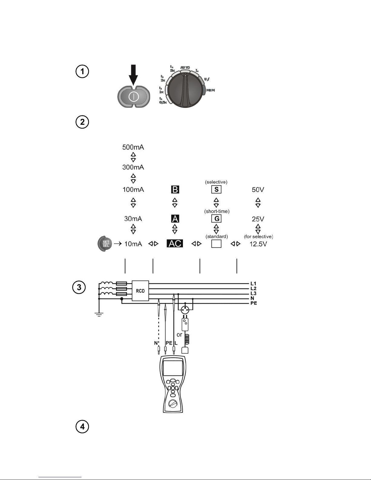
Start the
measurement
procedure
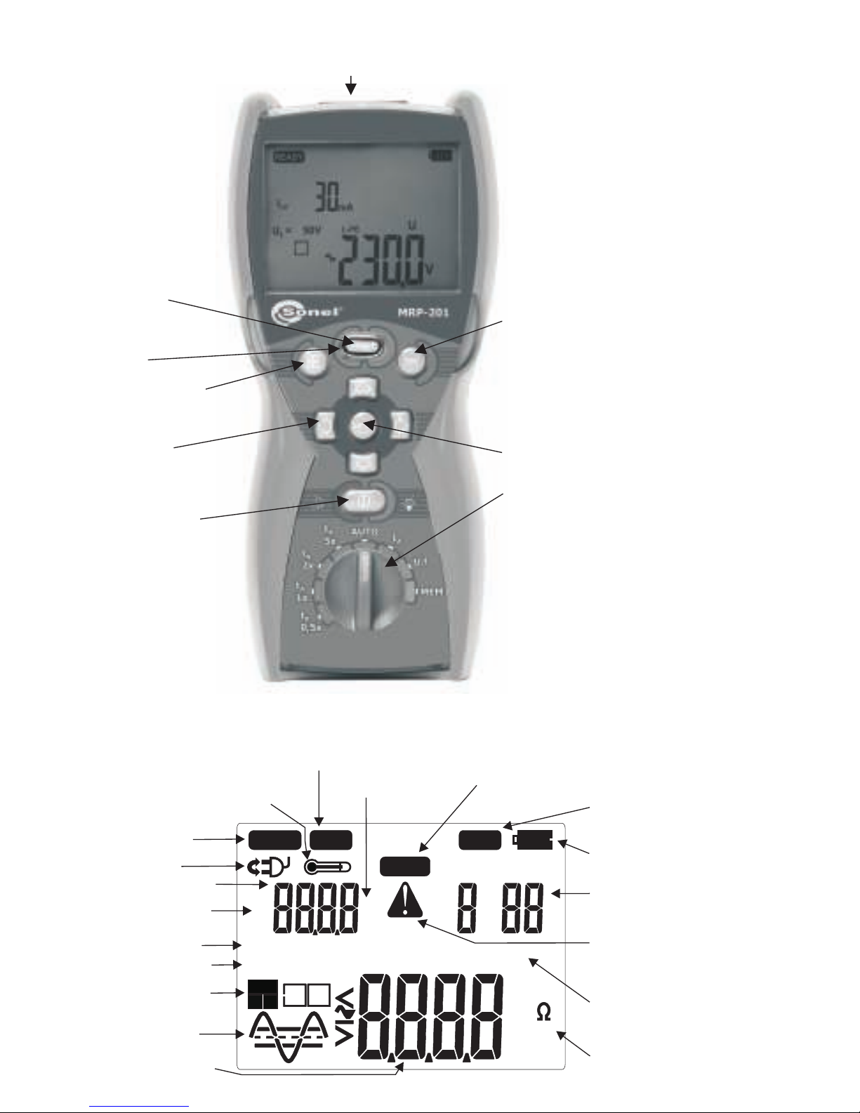
On and off function -
keep the button depressed
for some time to turn on
(in two steps) and off the
display lighting
ROTARY SWITCH FOR SELECTING FUNCTIONS
Selecting the measurement function:
-t 0,5x
A0,5I
- - RCD: 1I
- - RCD: 2I
- - RCD: 5I
- - RCD:
- - RCD:
- -
- -
- RCD: response time measurement for
response time measurement for
response time measurement for
response time measurement for
automatic measurement
response/tripping time measurement
measurement of voltage and frequency
View and erase the memory content and
data transmission
D
D
D
D
n
n
n
n
t 1x
t 2x
t 5x
AUTO
I
U,f
MEM
A
A
A
A
Approving selected function
ESC -return to previous function,
exit the function
Shift/selection:
right / left,
up / down
SET/SEL - - used for
entering meter settings and
selecting the digit to be
changed
Measuring terminals
Contact
electrode
DISPLAY
L and N leads
switched
Parameter configuration mode active
Additional display field Memory bank and memory
cell number
Memory storing or memory
viewing mode active
Symbol indicating
battery charge status
Warning - eimportant error messag
displayed, read the operating manual
Interference voltage causing
additional measurement uncertainty
IDnmultiplication factor
Safe contact voltage
RCD type
Current waveform
Values displayed on the main field
Main reading field
Units of displayed on the main field
SET
READY
Bank Cell
MEM
N
mA
U
k
s
m
VA
m
Hz
NOISE!
IDn
V
G
S
U =12.50V
L
x1/25
B
tA
AI
I
REU
m
?
AB
AC
IDn
L-PE
L-N RCD
!
Values displayed on
the additional field
Ready for
measurement
Maximum allowed temperature
inside the meter is exceeded.
Units of displayed
on the additional
field

OPERATING MANUAL
RCD TESTER
MRP-201
SONEL SA
ul. Wokulskiego 11
58-100 Świdnica, Poland
Version 1.05 07.01.2015

2
The MRP-201 meter is a modern, easy and safe measuring device. Please acquaint yourself with the
present manual in order to avoid measuring errors and prevent possible problems related to operation
of the meter.

3
CONTENTS
1SAFETY....................................................................................................................5
2MEASUREMENTS..................................................................................................6
2.1 SELECTION OF GENERAL MEASUREMENT PARAMETERS.........................................6
2.2 REMEMBERING THE LAST MEASUREMENT RESULT ................................................7
2.3 MEASUREMENT OF ALTERNATING VOLTAGE .........................................................8
2.4 MEASUREMENT OF VOLTAGE AND FREQUENCY.....................................................8
2.5 VALIDATION OF THE CONNECTIONS THE PROTECTIVE CONDUCTOR .......................8
2.6 MEASUREMENT OF RCDPARAMETERS.................................................................9
2.6.1 Measurement of RCD disconnection current.................................................9
2.6.2 Measurement of RCD disconnection time....................................................12
2.6.3 Automatic measurement of RCD parameters...............................................14
3MEMORY OF MEASUREMENT RESULTS.....................................................22
3.1 STORING THE MEASUREMENT RESULT DATA IN THE MEMORY.............................22
3.2 CHANGING THE CELL AND BANK NUMBER...........................................................24
3.3 VIEWING MEMORY DATA.....................................................................................24
3.4 DELETING MEMORY DATA...................................................................................25
3.4.1 Deleting bank data.......................................................................................25
3.4.2 Deleting the whole memory .........................................................................26
3.5 COMMUNICATION WITH PC.................................................................................27
3.5.1 Computer connection accessories ...............................................................27
3.5.2 Data transmission........................................................................................27
4TROUBLESHOOTING.........................................................................................29
5METER POWER SUPPLY...................................................................................31
5.1 MONITORING OF THE POWER SUPPLY VOLTAGE...................................................31
5.2 REPLACING BATTERIES (RECHARGEABLE BATTERIES).........................................31
5.3 GENERAL PRINCIPLES REGARDING USING NI-MH ACCUMULATORS.....................33
6CLEANING AND MAINTENANCE....................................................................34
7STORAGE ..............................................................................................................34
8DISMANTLING AND UTILISATION................................................................34
9TECHNICAL SPECIFICATIONS .......................................................................35
9.1 BASIC DATA ........................................................................................................35
9.2 ADDITIONAL DATA ACCORDING TO IEC 61557-6 (RCD).....................................38
10 EQUIPMENT .........................................................................................................39

4
10.1 STANDARD EQUIPMENT.......................................................................................39
10.2 OPTIONAL ACCESSORIES .....................................................................................39
11 MANUFACTURER ...............................................................................................40

5
1 Safety
MRP-201 meter is designed for performing check tests of protection against electric shock in
mains systems. The meter is used for making the measurements the results of which determine
safety of electrical installations. Therefore, in order to provide conditions for correct operation and the
correctness of the obtained results, the following recommendations must be observed:
Before you proceed to operate the meter, acquaint yourself thoroughly with the present manual
and observe the safety regulations and specifications determined by the producer.
Any application that differs from those specified in the present manual may result in a damage to
the device and constitute a source of danger for the user.
The device must be operated solely by appropriately qualified personnel with relevant certificates
to realise measurements of electric installation. Operation of the meter realised by unauthorised
personnel may result in damage to the device and constitute a source of danger for the user.
Using this manual does not exclude the need to comply with occupational health and safety
regulations and with other relevant fire regulations required during the performance of a particular
type of work. Before starting the work with the device in special environments, e.g. potentially fire-
risk/explosive environment, it is necessary to consult it with the person responsible for health and
safety.
It is unacceptable to operate the following:
A damaged meter which is completely or partially out of order,
A meter with damaged test leads insulation,
A meter stored for an excessive period of time in disadvantageous conditions (e.g. excessive
humidity). If the meter has been transferred from a cool to a warm environment of a high level
of relative humidity, do not realise measurements until the meter has been warmed up to the
ambient temperature (approximately 30 minutes).
It should be remembered that BAT message appearing on the display indicates that supply
voltage of the meter is too low. This message signals also that the batteries must be replaced or
the accumulator charged. Measurements performed by means of the meter whose supply voltage
is too low are burdened with additional errors that are impossible to be estimated by the user.
Such measurements must not be relied on in order to state correctness of protection of a network
tested.
Battery spill and damage to the meter may occur if discharged batteries are left in the meter.
Before measurements may commence, make sure the test leads are connected to the
appropriate measurement sockets.
Do not operate a meter with an open or incorrectly closed battery (accumulator) compartment or
power it from other sources than those specified in the present manual.
Repairs may be realised solely by an authorised service point.
ATTENTION!
Only standard and additional accessories for a given device should be used, as listed in
the "Equipment" section. Use of different accessories can lead to errors in the test
connection and can introduce additional measurement uncertainties.
Note:
An attempt to install drivers in 64-bit Windows 8 may result in displaying "Installation
failed" message.
Cause: Windows 8 by default blocks drivers without a digital signature.
Solution: Disable the driver signature enforcement in Windows.

6
Attention:
Due to continuous development of the meter’s software, the actual appearance of the
display, in case of some of the functions, may slightly differ from the display presented in
this operating manual.
2 Measurements
WARNING:
During RCD measurements, the earthed parts and parts accessible in the electrical
installation being tested must not be touched.
WARNING:
During a measurement, switching of the range switch is forbidden because it may damage
the meter and pose a threat to the user.
2.1 Selection of general measurement parameters
Keeping the SET/SEL button
depressed, turn on the meter and wait
for the parameter selection screen.
Use the , buttons to go to the next
parameter.
Use the , buttons to change the parameter
value. The value or symbol to be changed is
flashing.
The symbol indicates an active parameter,
the - symbol indicates an inactive one.
Set the parameters according to the following algorithm:

7
Parameter
Auto-OFF
Parameters
RCD-AUTO
Change
PIN
Power
source
Beeper
Program
update
Symbol(s)
Parameter
symbol(s)
...
Press ENTER to validate the last change and go to
the measurement function,
or
Press ESC to go the measurement function without
validating the changes.
Notes:
- Symbol in this case indicates positive phase/polarity, while symbol - negative. The same
applies to pulsed and direct current.
- Symbol indicates that no auto-off time has been set.
- RCD Auto mode settings are described in Section 2.6.3.
- PIN settings - see section 3.5.2 Data Transmission.
2.2 Remembering the last measurement result
The result of the latest measurement is remembered by the meter until a next measurement is
started or measurement settings are changed or the measuring function is changed by means of the
rotary switch or the meter is switched off. When you go to the output screen of a given function, you
can recall this result with the ESC button by pressing ENTER. Similarly, you can view the latest
measurement result after turning off and then turning on the meter (if the position of function selector
has not been changed).
8
2.3 Measurement of alternating voltage
The meter measures and displays alternating mains voltage in all measuring functions. This
voltage is measured for the frequencies within the range of 45..65 Hz. The test leads should be
connected as for a given measuring function.
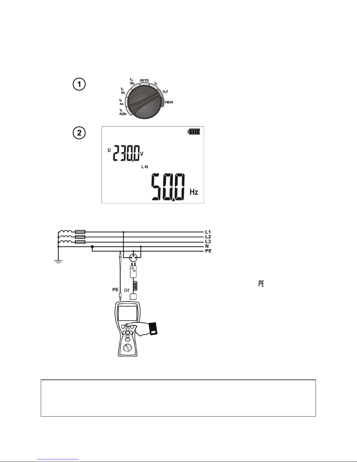
2.4 Measurement of voltage and frequency
Set the rotary switch in the U,f
position.
Read the result of
measurement: the
voltage on the
secondary display
field, the frequency of
the principal.
2.5 Validation of the connections the protective conductor
Notes:
WARNING:
When a dangerous voltage is detected on PE conductor, measurements must be imme-
diately stopped and a fault in the installation must be removed.
After connecting the meter according to the
drawing, touch the contact electrode with a finger
and wait for about 1 second. When voltage is
found on PE the meter displays symbol (error
in the installation; PE connected to the phase
conductor) and generates a continuous beep.
This option is available for all measuring
functions of residual current devices (RCD).
9
- The person making a measurement must ensure that he/she is standing on a non-insulated floor
during the measurement; otherwise the result of the measurement may be incorrect.
- The threshold value, which triggers the signal of exceeded allowable voltage on PE conduit, is
approximately 50 V.
2.6 Measurement of RCD parameters
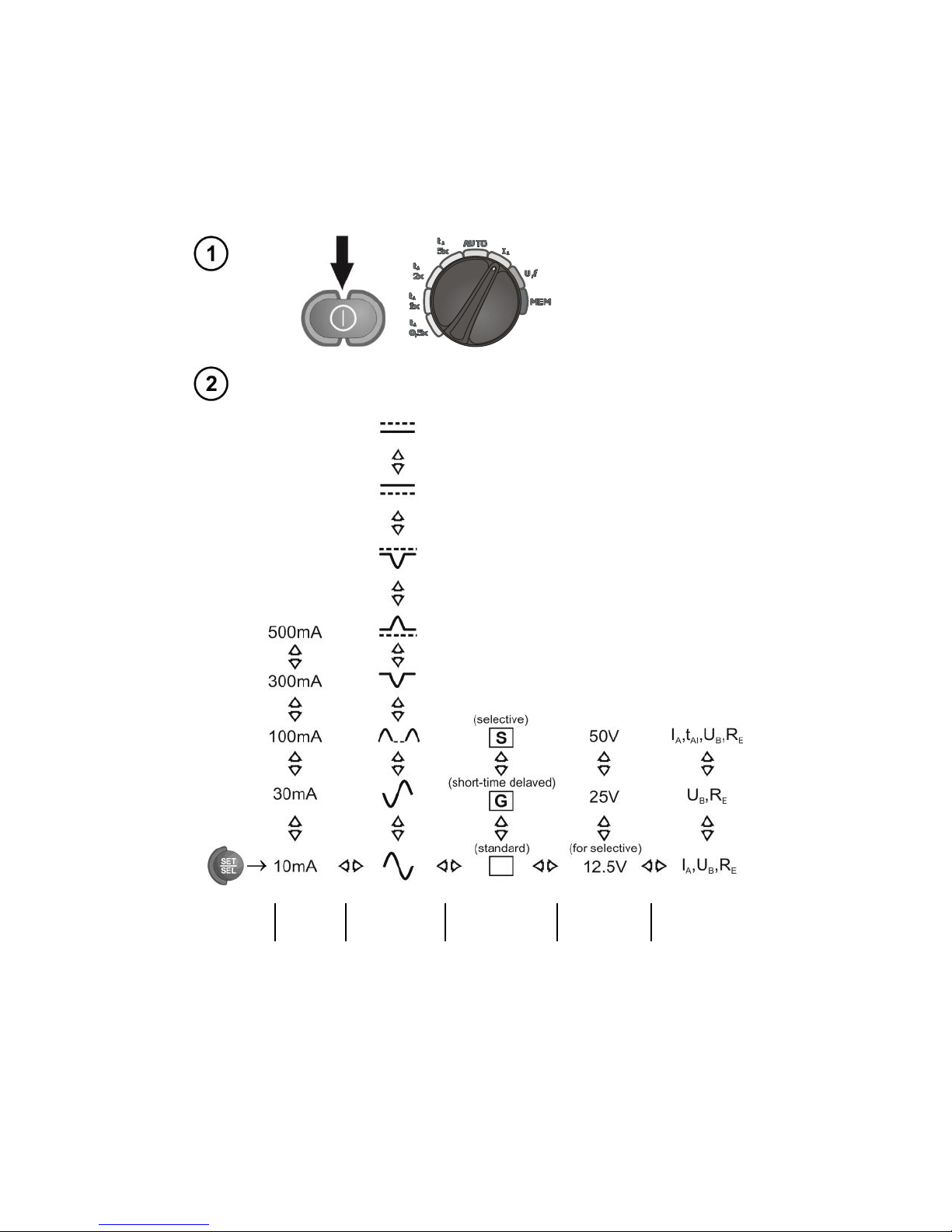
2.6.1 Measurement of RCD disconnection current
Turn on the meter.
Turn the rotary switch
to the position IA.
Set the parameters according to the following algorithm, and
according to the rules described in general parameters setting.
Parameter
In
Current
waveform
Type
of switch
UL
Measurement
mode

10
Connect
the test
leads
as shown
on the
drawing.
Connecting
N
conductor
is
necessary
for pulsed
current
with direct
current
offset and
for direct
current.
The meter is ready
for measurement.
UL-PE voltage
Perform measurement by pressing START push-
button.
Read the main
measurement result
IAcurrent.
To read additional results, press .
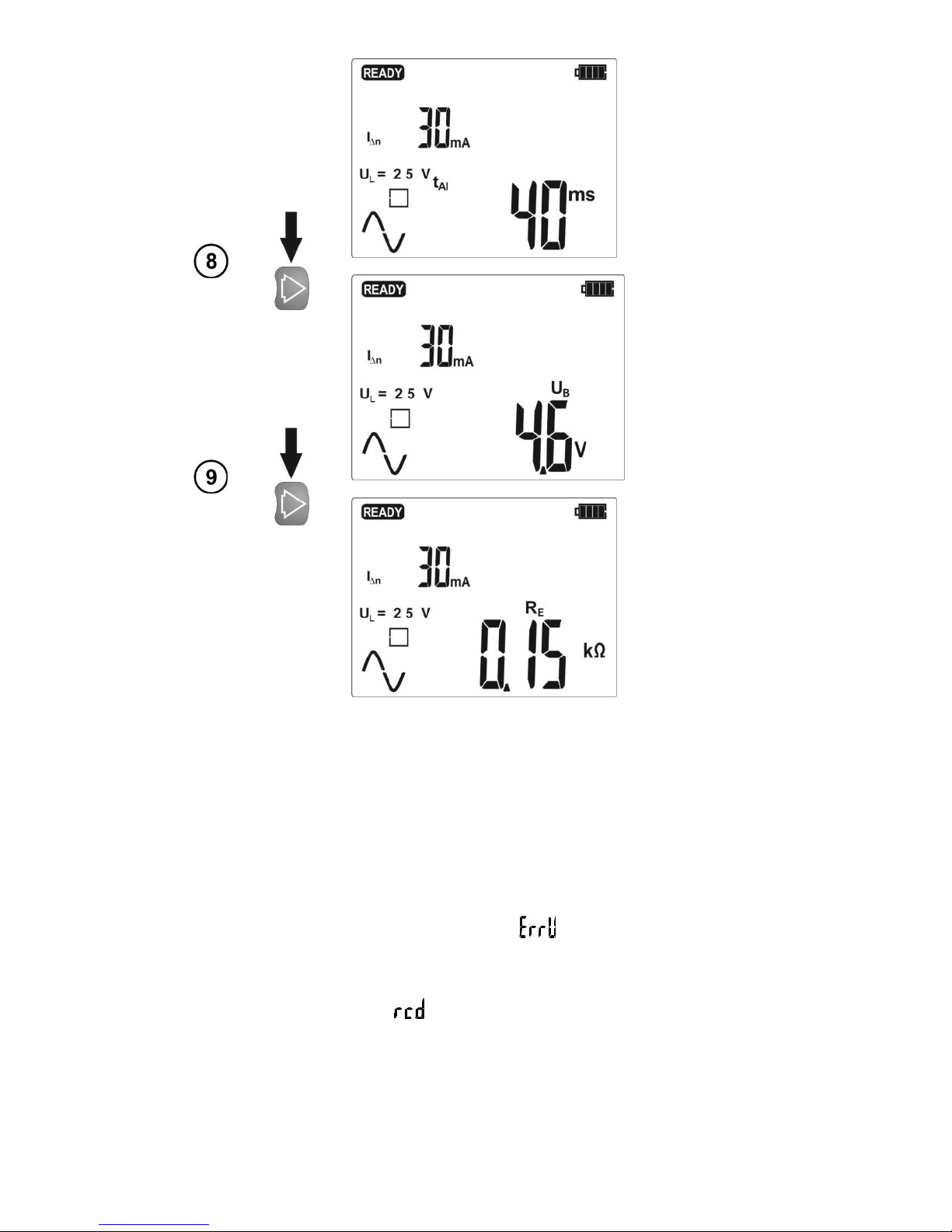
11
Response
time tAI at IA
current.
UBcontact
voltage.
Resistance-
to-earth RE
Notes:
- The value of I∆n and its multiplication factor along with current waveform must be selected in a
manner enabling the meter to perform the measurement. The set of measurement parameters, which
is not supported by the meter, can not be entered - when one parameter is entered the remaining
parameters change their values to default values (see Technical Specifications: Table of forced
current values).
- Measurement of response time tAI is not available for short-time delay switches and for selective
switches and for direct current.
- UBand REvalues are measured with test current 0,4I∆nwithout RCD tripping. If during this
measurement RCD is tripped, the following message is displayed for a while and the next
measurement (if applicable) (IAor tA) will not be performed.
- Due to the nature of the measurement (increase of IAcurrent in steps), measured
disconnection/response time tAI in this mode may include a positive error or as a result of RCD inertia,
the following symbol may be displayed: . If the result is not within the acceptable range for a given
RCD, repeat the measurement in tAmode (section 2.6.2).
- Enter the result into memory (see section 3.2) or press, ESC, to return to displaying only voltage
value. The last measurement result is stored until START button is pressed again or the position of
rotary switch is changed.

12
Additional information displayed by the meter
The meter is ready for measurement.
Voltage on terminals L and PE is not within the
measurable range.
L and N conductors have been switched (voltage between
terminals PE and N).
The temperature inside the meter has risen above the
limit, the measurement is blocked.
RCD is inactive.
Safe contact voltage exceeded.
REvalue is out of range.
The measurement cancelled with ESC.
The loss of voltage during the measurement.
After UBREmeasurement, IA(or tA) measurement has not
been performed because the values of REand mains
voltage did not allow to generate the required current
value.
or
Damaged current setting circuit. Try to perform
measurement again. If the message reappears, please
send the meter for repair.
2.6.2 Measurement of RCD disconnection time
Turn on the meter.
Turn the rotary switch
to a position for tA
measurement with
selected multiplication
factor of IΔn.
Set the parameters according to the following algorithm, and
according to the rules described in general parameters setting.

13
Parameter
In
Current
waveform
Type
of switch
UL
Measurement
mode
Connect
the test
leads
as shown
on the
drawing.
Connecting
N
conductor
is
necessary
for pulsed
current
with direct
current
offset and
for direct
current.
The meter is ready
for measurement.
UL-PE voltage

14
Perform measurement by pressing START push-
button.
Read the main
measurement
result: tAdisconnection
(response) time.
To read additional results, press .
UBcontact
voltage.
Resistance-
to-earth RE
Messages and information displayed by the meter as in Section 2.6.1.
2.6.3 Automatic measurement of RCD parameters
The meter enables automatic measurement of the following: RCD disconnection times (tA),
disconnection current (IA), touch voltage (UB) and resistance-to-earth (RE). In this mode, there is no
need to trigger the measurement foe every single measurement and the role of the user is reduced to
initiate the measurement and switch on RCD after each tripping.
MRP-201 provides two AUTO modes to be chosen from the main menu:
- FULL mode
15
- STANDARD mode
Mode selection is described in Section 2.1.
2.6.3.1 FULL mode
Turn on the meter.
Turn the rotary switch
to AUTO position.
If displayed parameters differ from those required, set them
according to the following algorithm, and according to the rules
described in general parameters setting.
Parameter
In
Type
of switch
Type
of switch
UL
Connect
test leads
according
to the
drawing.
Connecting
N
conductor
is
necessary
for pulsed
current
with direct
current
offset and
for direct
current.
The meter is ready
for measurement.

16
UL-PEvoltage
Press START push-button to start measurement.
After each activation
turn-on tested RCD.
Read the main
measurement result:
- good or -
bad.
Enter the result into memory by pressing ENTER, or see the components of the result and go to
displaying voltage values by pressing ESC.
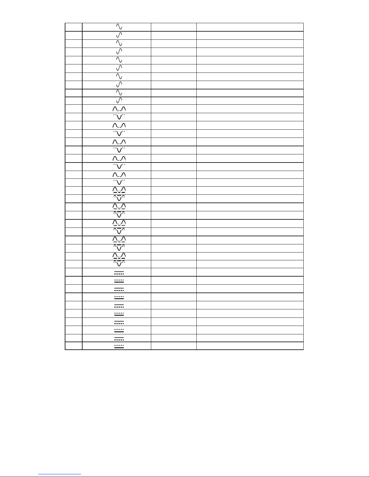
The meter provides the following measurements:
For RCD AC:
No.
Parameters
measured
Measurement conditions
In
multiplication
factor
Initial phase (polarization)
1.
UB, RE
2.
tA
0.5In
positive
3.
tA
0.5In
negative
4.*
tA
1In
positive
5.*
tA
1In
negative

17
6.*
tA
2In
positive
7.*
tA
2In
negative
8.*
tA
5In
positive
9.*
tA
5In
negative
10.*
IA
positive
11.*
IA
negative
* points in which an efficient RCD should be disconnected
For RCD A:
No.
Parameters
measured
Measurement conditions
In
multiplication
factor
Initial phase (polarization)
1.
UB, RE
2.
tA
0.5In
positive
3.
tA
0.5In
negative
4.*
tA
1In
positive
5.*
tA
1In
negative
6.*
tA
2In
positive
7.*
tA
2In
negative
8.*
tA
5In
positive
9.*
tA
5In
negative
10.*
IA
positive
11.*
IA
negative
12.*
tA
0.5In
positive
13.*
tA
0.5In
negative
14.*
tA
1In
positive
15.*
tA
1In
negative
16.*
tA
2In
positive
17.*
tA
2In
negative
18.*
tA
5In
positive
19.*
tA
5In
negative
20.*
IA
positive
21.*
IA
negative
22.*
tA
0.5In
positive
23.*
tA
0.5In
negative
24.*
tA
1In
positive
25.*
tA
1In
negative
26.*
tA
2In
positive
27.*
tA
2In
negative
28.*
tA
5In
positive
29.*
tA
5In
negative
30.*
IA
positive
31.*
IA
negative
* points in which an efficient RCD should be disconnected
For RCD B:
No.
Parameters
measured
Measurement conditions
In
multiplication
factor
Initial phase (polarization)
1.
UB, RE
18
2.
tA
0.5In
positive
3.
tA
0.5In
negative
4.*
tA
1In
positive
5.*
tA
1In
negative
6.*
tA
2In
positive
7.*
tA
2In
negative
8.*
tA
5In
positive
9.*
tA
5In
negative
10.*
IA
positive
11.*
IA
negative
12.*
tA
0.5In
positive
13.*
tA
0.5In
negative
14.*
tA
1In
positive
15.*
tA
1In
negative
16.*
tA
2In
positive
17.*
tA
2In
negative
18.*
tA
5In
positive
19.*
tA
5In
negative
20.*
IA
positive
21.*
IA
negative
22.*
tA
0.5In
positive
23.*
tA
0.5In
negative
24.*
tA
1In
positive
25.*
tA
1In
negative
26.*
tA
2In
positive
27.*
tA
2In
negative
28.*
tA
5In
positive
29.*
tA
5In
negative
30.*
IA
positive
31.*
IA
negative
32.*
tA
0.5In
positive
23.*
tA
0.5In
negative
24.*
tA
1In
positive
25.*
tA
1In
negative
26.*
tA
2In
positive
27.*
tA
2In
negative
28.*
tA
5In
positive
29.*
tA
5In
negative
30.*
IA
positive
31.*
IA
negative
* points in which an efficient RCD should be disconnected
Notes:
- The number of measured parameters depends on the settings entered in the main menu.
- UBand REare always measured.
- Automatic measurement is interrupted in the following cases:
the switch was tripped during the measurement of UBREor tAat the half value of IΔn,
the switch did not trip during other component measurements,
the value of safe voltage ULhas been exceeded,
voltage was disconnected during one of the component measurements,
Table of contents
Other Sonel Test Equipment manuals


Sonel
Sonel S-50 DC User manual

Sonel
Sonel TKF-13 User manual

Sonel
Sonel TKF-12 User manual

Sonel
Sonel UV-260 Corona Camera User manual

Sonel
Sonel P-2 User manual

Sonel
Sonel S-36 VLF User manual

Sonel
Sonel PAT-10 User manual

Sonel
Sonel P-3 User manual

Sonel
Sonel VT-3 User manual

Sonel
Sonel PAT-806 User manual


