Sonel VT-3 User manual

1
INSTRUKCJA OBSŁUGI 3
USER MANUAL 6
MANUAL DE USO 9
VT-3
v1.02 09.12.2019

Dioda latarki
Pokrywa baterii
Włącznik latarki
Klips
Przycisk zakresu pomiarowego 12…1000 V
Włącznik testera
Wskaźniki LED
Doświetlenie obszaru pomiarów
Końcówka pomiarowa
Flashlight
Battery cover
Flashlight button
Clip
Button of 12…1000 V measurement range
On/off button
LED indicators
Illuminating the measurement area
Detector tip
Diodo de linterna
Tapa de pilas
Interruptor de linterna
Clip
Botón del rango de medición de 12...1000 V
Interruptor del probador
Indicadores LED
Iluminación del área de medición
Punta de medición

VT-3 –INSTRUKCJA OBSŁUGI
3
INSTRUKCJA OBSŁUGI
BEZDOTYKOWY TESTER NAPIĘCIA PRZEMIENNEGO
VT-3
1 Ostrzeżenia
Tester jest przeznaczony do wykrywania obecności napięcia. Może być użytkowany jedynie przez
personel z odpowiednimi kwalifikacjami.
Zanim użyjesz testera, zapoznaj się z instrukcjąobsługi i postępuj według zasad bezpieczeństwa.
Zabezpieczenia testera mogą nie ochronić użytkownika, jeżenie nie będą stosowane zgodnie z in-
strukcjami producenta.
Zanim użyjesz testera, potwierdź jego sprawność, sprawdzając go na znanym napięciu AC (np.
najbliższe dostępne gniazdo będące pod napięciem).
Rodzaj i grubość izolacji, odległość od źródła napięcia, przewody ekranowane oraz inne czynniki
mogą wpłynąć na skuteczność działania testera. W przypadku braku pewności co do wyniku testu,
stwierdź obecność napięcia w inny sposób.
Nie używaj testera:
odo stwierdzania braku napięcia,
ojeśli jest on uszkodzony lub nie działa prawidłowo. W razie wątpliwości zastąp go innym,
odo napięć wyższych niż górny zakres pomiarowy widniejący na obudowie.
Zachowaj ostrożność przy napięciach powyżej 30 V AC – istnieje ryzyko porażenia.
Przestrzegaj wszystkich obowiązujących przepisów bezpieczeństwa. Pracując w pobliżu obwodów
będących pod napięciem – w szczególności tam, gdzie może zaistnieć łuk elektryczny – stosuj
środki ochrony osobistej.
Nie użytkuj testera, gdy występuje ostrzeżenie o niskim stanie naładowania baterii. Natychmiast
wymień baterie na nowe.
Niedziałająca latarka może oznaczać uszkodzenie urządzenia lub wyczerpanie baterii.
Gdy urządzenie jest włączone, komora baterii musi być zamknięta.
Patrzenie bezpośrednio w lampę LED może uszkodzić wzrok.
Zabrudzenie i zawilgocenie powierzchni urządzenia może zagrażać porażeniem elektrycznym.
UWAGA!
Osoby nieuprawnione nie mogą dokonywać demontażu przyrządu.
Rozbiórka i naprawy przyrządu mogą być realizowane wyłącznie przez osoby z odpo-
wiednimi kwalifikacjami.
2 Symbole bezpieczeństwa
Niniejszy symbol, umieszczony w pobliżu innego symbolu lub gniazda wskazuje, że użytkownik
winien zapoznać się z dalszymi informacjami zamieszczonymi w instrukcji obsługi.
Niniejszy symbol, umieszczony w pobliżu gniazda wskazuje, że w warunkach normalnego
użytkowania istnieje możliwość wystąpienia niebezpiecznych napięć.
II klasa ochronności – izolacja podwójna lub wzmocniona
Niniejszy symbol oznacza, że urządzenia nie wolno wyrzucać do zwykłych pojemników na
odpady, tylko do wyznaczonego punktu zbiórki odpadów elektronicznych.
Przyrząd spełnia wymogi prawne Unii Europejskiej.
CAT
Kategoria pomiarowa przyrządu.
VT-3 –INSTRUKCJA OBSŁUGI
4
3 Obsługa
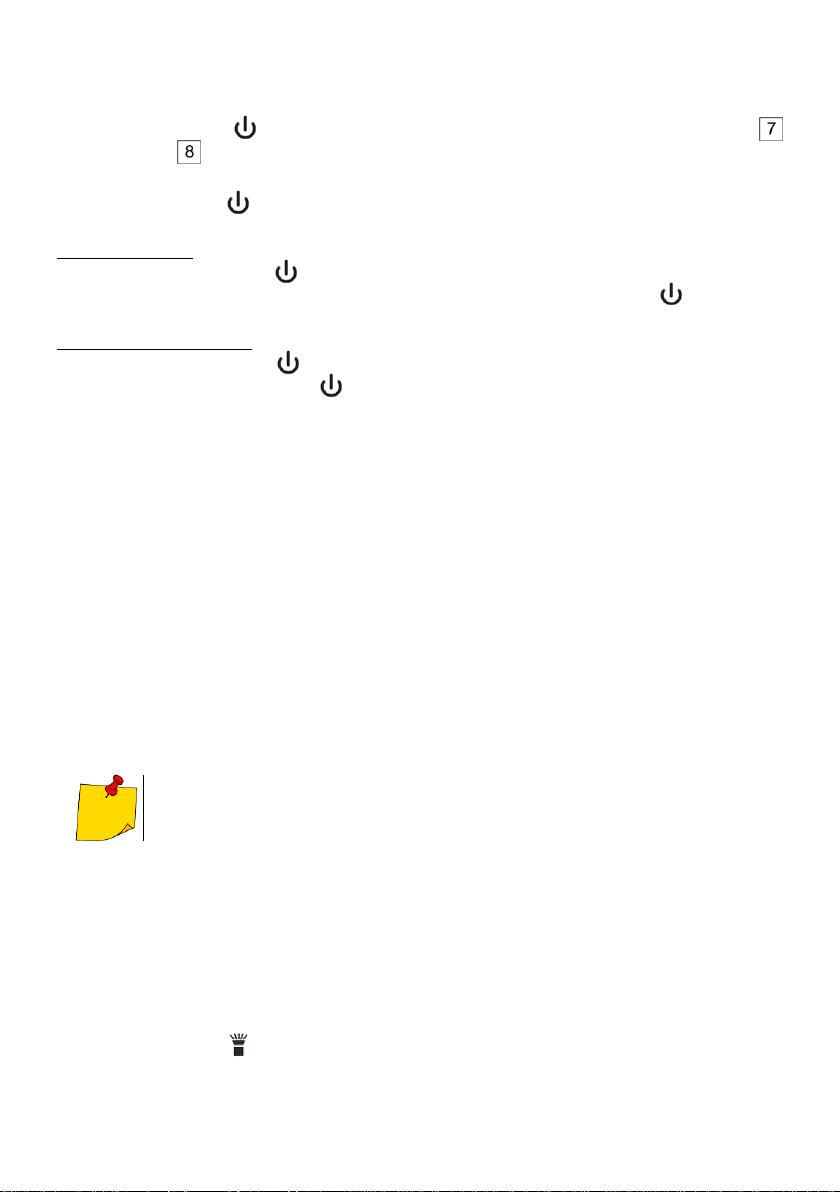
3.1 Włączanie testera
Naciśnij krótko przycisk . Rozlegnie się pojedynczy sygnał dźwiękowy i zapali zielona dioda
wraz z modułem . Tester jest włączony i gotowy do użycia.
3.2 Wyłączanie testera
Naciśnij krótko przycisk . Rozlegnie się podwójny sygnał dźwiękowy, a zielona dioda zgaśnie.
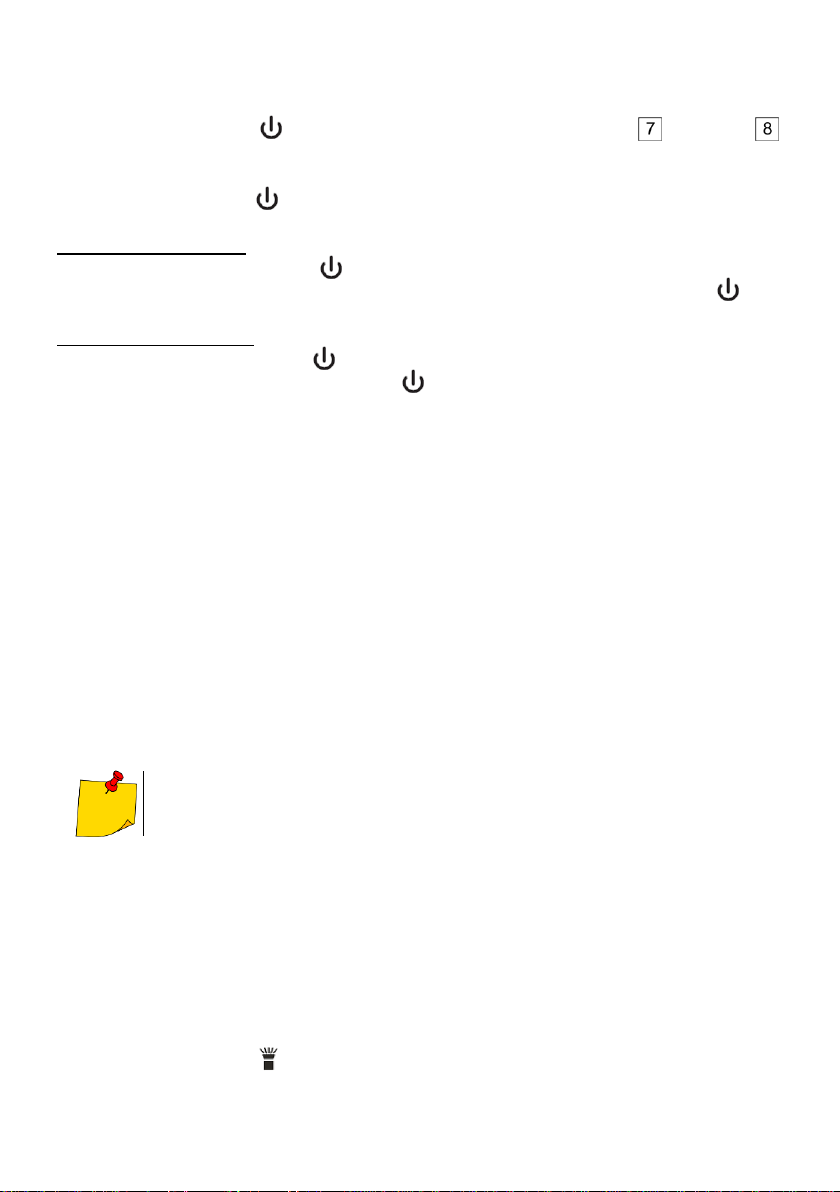
3.3 Wyłączenie i włączanie sygnalizacji dźwiękowej
a) Włączając tester
Naciśnij i przytrzymaj przycisk do czasu, aż zaświeci się zielona dioda. Tester działa teraz bez sy-
gnalizacji dźwiękowej. Aby przywrócić sygnalizację, naciśnij i przytrzymaj przycisk do czasu, aż
zielona dioda zacznie migać, a sygnalizator wyda sygnał dźwiękowy.
b) Przy włączonym testerze
Naciśnij i przytrzymaj przycisk do czasu, aż zielona dioda zacznie migać. Aby przywrócić sygnali-
zację, naciśnij i przytrzymaj przycisk do czasu, aż zielona dioda zacznie migać, a sygnalizator wy-
da sygnał dźwiękowy.
3.4 Sprawdzenie testera
Zanim użyjesz testera:
sprawdź, czy świeci zielona dioda LED,
sprawdź tester na znanym napięciu AC, mieszczącym się w zakresie pomiarowym.
3.5 Pomiar napięć w Trybie Wysokim (100…1000 V AC)
Zbliż tester końcówką pomiarową do testowanego napięcia AC. Jeśli przyrząd wykrywa napięcie
mieszczące się w zakresie pomiarowym, zgaśnie zielona dioda, zapali się czerwona i rozlegnie się
modulowany sygnał dźwiękowy.
3.6 Pomiar napięć w Trybie Niskim (12…1000 V AC)
Naciśnij i przytrzymaj przycisk 12 V. Dioda zmieni kolor z zielonego na pomarańczowy, sygnalizując
zmianę zakresu pomiarowego. Trzymając wciśnięty przycisk 12 V, zbliż tester końcówką pomiarową
do testowanego napięcia AC. Jeśli napięcie zostanie wykryte, pomarańczowa dioda zgaśnie, dioda
czerwona zacznie migać i rozlegnie się sygnał akustyczny.
Częstotliwość sygnałów świetlnych i akustycznych będzie rosnąć tym bardziej, im bliżej testowanego
napięcia znajdzie się tester. Jeśli wykryte zostanie wysokie napięcie, tryb pomiarowy przełączy się au-
tomatycznie na Tryb Wysoki: czerwona dioda zaświeci w sposób ciągły i rozlegnie się modulowany
sygnał akustyczny.
Tester nie pokazuje wartości napięcia.
Przyczyną automatycznej zmiany trybu na Wysoki może być rodzaj i grubość izola-
cji, odległość od źródła napięcia lub inne czynniki.
3.7 Wskaźnik rozładowania baterii
Jeśli zielona dioda LED nie świeci, wymień baterie. Gdy tester jest włączony, a poziom naładowania
baterii jest zbyt niski do poprawnych testów, sygnalizator wyda trzykrotny sygnał dźwiękowy, a zielona
dioda zgaśnie, dając do zrozumienia, że testera nie można użytkować. Wymień baterie, by kontynuo-
wać testy.
3.8 Automatyczne wyłączenia
Aby przedłużyć życie baterii, tester wyłączy się automatycznie po upływie ok. 5 minut bezczynności.
Wyłączając się, przyrząd wyda trzykrotny sygnał dźwiękowy, a zielona dioda zgaśnie.
3.9 Latarka
Naciśnij krótko przycisk , by włączyć lub wyłączyć latarkę. Aby przedłużyć życie baterii, latarka wyłączy
się automatycznie po upływie ok. 5 minut. Wyłączając się, tester wyda dwukrotny sygnał dźwiękowy.

VT-3 –INSTRUKCJA OBSŁUGI
5
Jeśli poziom naładowania baterii jest zbyt niski, by latarka świeciła w sposób sku-
teczny, tester zasygnalizuje ten fakt wydając trzykrotny sygnał dźwiękowy. Następ-
nie latarka zgaśnie.
Moduł testowania napięcia posiada swoje własne kryterium baterii i w powyższej sy-
tuacji może wciąż działać. W celu weryfikacji postępuj zgodnie z punktem 3.4.
4 Wymiana baterii
Ostrożnie odkręć pokrywę baterii od tylnej części obudowy (element z diodą latarki).
Usuń stare baterie i włóż nowe, zwracając uwagę na biegunowość.
Ostrożnie umieść pokrywę baterii tak, by sprężyny dotykały styków.
Zakręć pokrywę do oporu, nie nadużywając siły.
Sprawdź tester na znanym napięciu AC, mieszczącym się w zakresie pomiarowym.
UWAGA!
Wymieniając baterie upewnij się, że zakręcasz pokrywę baterii w sposób pewny, by
zachować stopień ochrony IP67. Luźna lub zbyt mocno przykręcona pokrywa może
osłabić wodoszczelność i pyłoszczelność.
Instalując baterie po raz pierwszy, usuń z zestyków nakrętki naklejkę ochronną.
Wyjmij baterie, jeśli produkt nie będzie używany przez dłuższy czas.
5 Specyfikacja techniczna
a) kategoria pomiarowa zgodnie z PN-EN 61010-1.......................................................CAT IV 1000 V
b) stopień ochrony zgodnie z PN-EN 60529..................................................................................IP67
c) stopień zanieczyszczenia ..............................................................................................................2
d) zakresy wykrywania napięcia.................................................................................100…1000 V AC
................................................................................................................................12…1000 V AC
e) zakres częstotliwości .......................................................................................................50 / 60 Hz
f) czas bezczynności do samowyłączenia ...................................................................................5 min
g) wskaźniki.........................diody LED (zielona, pomarańczowa, czerwona), sygnalizator dźwiękowy
h) latarka ................................................................................................ dioda LED biała z soczewką
i) zasilanie..........................................................................................................2x bateria AAA 1,5 V
j) temperatura robocza.....................................................................................................0°C…+50°C
k) temperatura przechowywania....................................................................................-10°C…+60°C
l) wilgotność.......................................................................................................................maks. 80%
m) wysokość robocza ............................................................................................................... 2000 m
n) wymiary............................................................................................................... 160 x 23 x 25 mm
o) masa....................................................................................................................................... 78 g
p) masa bez baterii....................................................................................................................... 55 g
q) zgodność z wymaganiami................................................................................................EMC, LVD
r) zgodność z wymaganiami norm.......................PN-EN 61010-1, PN-EN 61326-1, PN-EN61326-2-2
..............................................PN-EN 61010-031+A1, PN-EN 61010-02-032, PN-EN 61010-02-033
Wyprodukowano w Chinach na zlecenie SONEL S.A.

VT-3 –USER MANUAL
6
USER MANUAL
CONTACTLESS AC VOLTAGE TESTER
VT-3
1 Warnings
The tester is used for voltage detecting. It must be used by skilled personnel only.
Before using the tester, read the manual and follow its safety guidelines. Protection measures
used in the tester may be ineffective, if not applied in accordance with manufacturer's instructions.
Before using the tester, check if its operational by testing it on a known AC voltage (i.e. next appli-
cable socket with live voltages).
The type and thickness of the insulation, distance from the power source, shielded cables and
other factors may affect the operation of the tester. If you are unsure about the test result, check
the presence of voltage in a different way.
Do not use the tester:
oto test the absence of voltages,
oif it is damaged or not working properly. If in doubt, replace it with another,
ofor voltages higher than the upper measuring range indicated on the housing.
Be careful when working with voltages above 30 V AC - there is a risk of electric shock.
Comply with all applicable safety regulations. When working near live circuits (especially in places
where an electric arc may be generated), use personal protective equipment.
Do not operate the tester, when there is a warning of low battery level. Immediately replace the
batteries with new ones.
Inoperative flashlight may indicate damage to the device or discharged batteries.
When the device is turned ON, the battery compartment must be closed.
Looking directly into the LED lamp may damage your eyes.
Dirt and moisture of the device may generate a risk of electrical shock.
NOTE!
Unauthorized persons are not allowed to disassemble the device.
Disassembling and repairs of the device must be done by skilled persons only.
2 Safety symbols
This symbol located near another symbol or terminal, indicates that the user should read
the further information contained in the manual.
This symbol located near the terminal, indicates that in normal use there is a possibility of
dangerous voltages.
Protection class II - double or reinforced insulation
This symbol indicates that the device must not be disposed of into any household waste
containers, but must be provided to a designated collection point for electronic waste.
The device meets the legal requirements of the European Union.
CAT
Measurement category of the instrument.
VT-3 –USER MANUAL
7
3 Operation
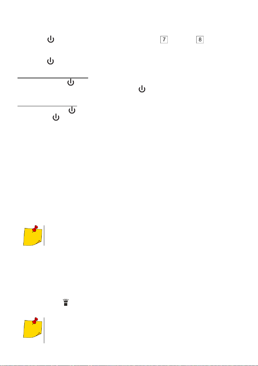
3.1 Switching the tester ON
Press shortly . You will hear a single beep and the green LED and module will light up. The
tester is turned ON and ready to use.
3.2 Switching the tester OFF
Press shortly . You will hear a double beep, and the green LED will go out.
3.3 Disabling and enabling sound signalling
a) When switching the tester ON
Press and hold button until the green LED activates. Now, the tester works without sound signals.
To restore the sound signalling, press and hold button until the green LED starts flashing and the
tester beeps.
b) When the tester is active
Press and hold button until the green LED starts to flash. To restore the sound signalling, press
and hold button until the green LED starts flashing and the tester beeps.
3.4 Checking the tester
Before using the tester:
check whether the green LED is ON,
check the tester on a known AC voltage within the measuring range.
3.5 Voltage measurement in High Mode (100 ... 1000 V AC)
Approach the measuring tip of the tester to the tested AC voltage. If the device detects a voltage within
the measuring range, the green LED goes out, the red LED is activated and a modulated beep is emit-
ted.
3.6 Voltage measurement in Low Mode (12…1000 V AC)
Press and hold the 12 V button. LED changes from green to orange to indicate the change of the
measuring range. While pressing the 12 V button, approach the measuring tip of the tester to the
tested AC voltage. If the voltage is detected, the orange LED goes out, the red LED starts flashing and
a beep is emitted.
The frequency of light and sound signals increases, when the tester is closer to the tested voltage. If
the high voltage is detected, the measurement mode automatically switches to 'High Mode': red LED
lights continuously and a modulated beep is emitted.
The tester does not show the voltage value.
The cause of automatic mode change to 'High Mode' may be the type and thickness
of the insulation, distance from the power source or other factors.
3.7 Indicator of discharged batteries
If the green LED is not active, replace the batteries. When the tester is turned ON and the battery level
is too low for proper testing, the tester will beep three times and the green LED will go out, indicating
that the tester cannot be used. Replace the batteries to continue testing.
3.8 Auto-Off
To prolong battery life, the tester will switch OFF automatically after approx. 5 minutes of inactivity.
During the switching OFF process, the device will beep three times and the green LED will go out.
3.9 Flashlight
Shortly press button , to turn ON/OFF the flashlight. To prolong battery life, the flashlight will switch OFF
automatically after approx. 5 minutes The Auto-Off is signalled by double beep.
If the battery level is too low for sufficient flashlight operation, the tester will indicate
this fact by three beeps. Then the flashlight will go out.
The module for voltage testing has own criterion for the batteries and in the above
situation it may still running. In order to verify it, follow sec. 3.4.
VT-3 –USER MANUAL
8
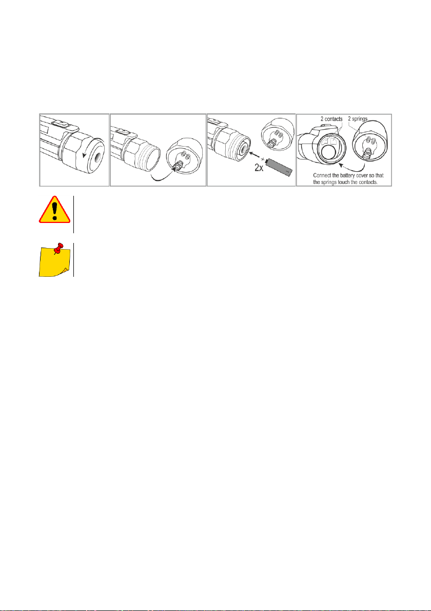
4 Replacing batteries
Carefully unscrew the battery cover a the back of the housing (element with flashlight LED).
Remove old batteries and insert new ones, paying attention to their polarity.
Carefully align the battery cover, ensure that the springs touch the contacts.
Screw the cover onto tester until it feels tight, but do not use excessive force.
Check the tester on a known AC voltage within the measuring range.
NOTE!
When replacing the batteries, make sure that you tightening the battery cover firmly to
maintain protection level of IP67. When the cover is too loose or too tight, the water-
proof and dustproof properties may be limited.
When installing the batteries for the first time, remove the protective sticker from the
contacts.
Remove the batteries, if the product is not to be used for a long time.
5 Technical Specifications
a) measurement category according to EN 61010-1.....................................................CAT IV 1000 V
b) Ingress Protections rating in accordance with EN 60529 ..........................................................IP67
c) contamination level........................................................................................................................2
d) voltage detection ranges .......................................................................................100…1000 V AC
................................................................................................................................12…1000 V AC
e) frequency range ..............................................................................................................50 / 60 Hz
f) time to AUTO-OFF ................................................................................................................. 5 min
g) indicators .....................................................................................LED's (green, orange, red), beep
h) flashlight........................................................................................................... white LED with lens
i) power supply..................................................................................................2 x AAA 1.5 V battery
j) operating temperature ..................................................................................................0°C…+50°C
k) storage temperature..................................................................................................-10°C…+60°C
l) humidity............................................................................................................................max. 80%
m) operational altitude............................................................................................................. 2000 m
n) dimensions......................................................................................................... 160 x 23 x 25 mm
o) weight...................................................................................................................................... 78 g
p) weight without batteries........................................................................................................... 55 g
q) compliance with the requirements of ...............................................................................EMC, LVD
r) compliance with the requirements of standards ................EN 61010-1, EN 61326-1, EN61326-2-2
................................................................EN 61010-031+A1, EN 61010-02-032, EN 61010-02-033
Made in China for SONEL S.A.
VT-3 –MANUAL DE USO
MANUAL DE USO
PROBADOR DE CORRIENTE ALTERNA SIN CONTACTO
VT-3
1 Advertencias
El probador se utiliza para detectar tensión. Debe ser utilizado solo por personal calificado.
Antes de usar el probador, leer el manual de instrucciones y seguir las medidas de seguridad.
Las medidas de seguridad del probador pueden no proteger al usuario si no se aplican de
acuerdo con las instrucciones del fabricante.
Antes de usar el probador, comprobar si funciona correctamente en la tensión alterna conocida
(es decir, el siguiente enchufe aplicable con persencia de tensiones).
El tipo y grosor de aislamiento, la distancia de la fuente de alimentación, los cables apantallados y
otros factores pueden afectar la eficacia del probador. Si no está seguro acerca del resultado de
la prueba, compruebe la presencia de tensión de otra forma.
No usar el probador:
opara probar la ausencia de tensiones,
osi está dañado o no funciona correctamente. En caso de duda, reemplazarlo por otro.
opara la tensión más alta que el rango superior que aparece en la carcasa.
Tener cuidado con tensiones superiores a 30 V AC por el peligro de descarga eléctrica.
Cumplir con todas las normas de seguridad aplicables. Al trabajar cerca de circuitos bajo tensión -
en particular cuando puede haber un arco eléctrico- usar el equipo de protección personal.
No utilizar el probador, cuando hay una advertencia de pilas agotadas. Reemplazar
inmediatamente las pilas por otras nuevas.
Si la linterna no funciona, esto puede significar que el dispositivo está dañado o las pilas están agotadas.
Cuando el dispositivo está encendido, el compartimento de pilas debe estar cerrado.
Mirar directamente la lámpara LED puede dañar la vista.
La suciedad y la humedad de la superficie del dispositivo puede causar la descarga eléctrica.
¡ATENCIÓN!
Las personas no autorizadas no pueden desmontar el dispositivo.
El desmontaje y las reparaciones del dispositivo deben ser realizados única-mente
por personal calificado.
2 Símbolos de seguridad
Este símbolo, situado cerca de otro símbolo o un enchufe indica que el usuario debe
consultar más información en el manual de instrucciones.
Este símbolo, situado cerca del enchufe sugiere que en condiciones normales de uso,
existe la posibilidad de tensiones peligrosas.
clase de protección II - aislamiento doble y reforzado
Este símbolo significa que el dispositivo no debe ser desechado a contenedores de
residuos domésticos, sino que se lo debe entregar a un punto de recogida de desechos
electrónicos.
El dispositivo cumple con los requisitos legales de la Unión Europea.
CAT
Categoría de medición del dispositivo.
VT-3 –MANUAL DE USO
3 Uso
3.1 Encendido del probador
Pulsar brevemente el botón . Se oirá un pitido y se encenderá el diodo verde y el módulo .
El probador está encendido y listo para usar.
3.2 Apagado del probador
Pulsar brevemente el botón . Se oirá un doble pitido y el diodo verde se apagará.
3.3 Desactivación y activación de los señales de sonido
a) Al encender el probador
Pulsar y mantener pulsado el botón hasta que se encienda el diodo verde. El probador funciona
ahora sin señales de sonido. Para restaurar las señales, pulsar y mantener pulsado el botón hasta
que el diodo verde comience a parpadear y se oirá una señal.
b) Con el probador activado
Pulsar y mantener pulsado el botón hasta que el diodo verde empiece a parpadear. Para restaurar
las señales, pulsar y mantener pulsado el botón hasta que el diodo verde comience a parpadear y
se oirá una señal.
3.4 Comprobación del probador
Antes de usar el probador:
comprobar si se ilumina el diodo verde
comprobar el probador en la tensión alterna conocida y que está en el rango de medición.
3.5 Medición de tensiones en Modo Alto (100...1000 V AC)
Acercar la punta de medición del probador a la tensión alterna examinada. Si el dispositivo detecta la
tensión dentro del rango de medición, el diodo verde se apagará, el diodo rojo se encenderá y se oírla
la señal modulada.
3.6 Medición de tensiones en Modo Bajo (12...1000 V AC)
Pulsar y mantener pulsado el botón 12 V. El diodo cambiará de color verde a naranja para indicar el
cambio del rango de medición. Mantener pulsado el botón 12 V y acercar la punta de medición del
probador a la tensión alterna examinada. Si se detecta la tensión, el diodo naranja se apagará, el
diodo rojo parpadeará y se oirá una señal.
La frecuencia de las señales de luz y sonido crecerá aún más, cuanto más cerca esté el probador
respecto a la tensión examinada. Si se detecta la alta tensión, el modo de medición cambiará
automáticamente al Modo Alto: el diodo rojo estará encendido continuamente y emitirá una señal
modulada.
El probador no muestra el valor de la tensión.
La causa del cambio automático de modo a Alto puede ser el tipo y grosor de
aislamiento, la distancia de la fuente de alimentación u otros factores.
3.7 Indicador de pila descargada
Si el diodo verde no está encendido, reemplazar las pilas. Cuando el probador está encendido y el
nivel de pilas es demasiado bajo para realizar las pruebas adecuadas, se oirá tres veces una señal, el
diodo verde se apagará, dando a entender que no se puede utilizar el probador. Reemplazar las pilas
para continuar con las pruebas.
3.8 Apagado automático
Para prolongar la vida útil de las pilas, el probador se apagará automáticamente después de unos 5
minutos de inactividad. Al apagarse, el dispositivo emitirá tres veces una señal y el diodo verde se
apagará.
3.9 Linterna
Pulsar brevemente el botón para encender o apagar la linterna. Para prolongar la vida útil de las pilas,
la linterna se apagará automáticamente después de unos 5 minutos. Al apagarse, el probador emitirá dos
veces una señal.

VT-3 –MANUAL DE USO
Si el nivel de las pilas es demasiado bajo para que la linterna ilumine de una
manera eficaz, el probador indicará este hecho al emitir tres señales. A
continuación, la linterna se apagará.
El módulo de comprobar la tensión tiene su propio criterio de pilas y en la situación
anterior puede seguir funcionando. Para verificarlo, seguir según el punto 3.4.
4 Reemplazo de pila
Desenroscar con cuidado la tapa de pilas en la parte posterior de la carcasa (elemento con diodo
de linterna).
Retirar las pilas desgastadas e insertar las nuevas prestando atención a la polaridad.
Colocar con cuidado la tapa de pilas de modo que las muelles toquen los contactos.
Apretar bien la tapa sin demasiada fuerza.
Comprobar el probador en la tensión alterna conocida y que está en el rango de medición.
¡ATENCIÓN!
Al reemplazar las pilas, asegurarse de cerrar bien la tapa para mantener la protección
IP67. La tapa apretada demasiado fuerte o floja puede debilitar la resistencia al agua
y al polvo.
Al insertar las pilas por primera vez, retirar la etiqueta protectora de los contactos de
tuerca.
Retirar las pilas si el producto no se utiliza durante mucho tiempo.
5 Especificaciones técnicas
a) categoría de medida según EN 61010-1...................................................................CAT IV 1000 V
b) grado de protección según EN 60529:......................................................................................IP67
c) grado de contaminación ................................................................................................................2
d) rangos de detección de tensión .............................................................................100…1000 V AC
................................................................................................................................12…1000 V AC
e) rango de frecuencia.........................................................................................................50 / 60 Hz
f) tiempo de inactividad para apagado automático ......................................................................5 min
g) indicadores.......................................................... diodos LED (verde, naranja, rojo), señal acústica
h) linterna ................................................................................................ diodo LED blanco con lente
i) alimentación .........................................................................................................2x pila AAA 1,5 V
j) temperatura de funcionamiento ....................................................................................0°C…+50°C
k) temperatura de almacenamiento ...............................................................................-10°C…+60°C
l) humedad..........................................................................................................................máx. 80%
m) altura de funcionamiento ..................................................................................................... 2000 m
n) dimensiones........................................................................................................160 x 23 x 25 mm
o) peso........................................................................................................................................ 78 g
p) peso sin pilas............................................................................................................................ 55 g
q) cumple con los requisitos de............................................................................................EMC, LVD
r) conformidad con los requisitos de las normas ...................EN 61010-1, EN 61326-1, EN61326-2-2
................................................................EN 61010-031+A1, EN 61010-02-032, EN 61010-02-033
Fabricado en China para SONEL S.A.
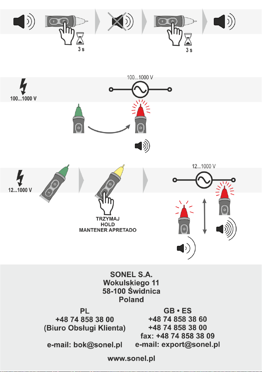
Table of contents
Languages:
Other Sonel Test Equipment manuals

Sonel
Sonel P-3 User manual

Sonel
Sonel UV-260 Corona Camera User manual

Sonel
Sonel P-2 User manual

Sonel
Sonel P-4 User manual

Sonel
Sonel PAT-10 User manual

Sonel
Sonel S-36 VLF User manual

Sonel
Sonel PAT-806-IT User manual

Sonel
Sonel MIC-10s1 User manual

Sonel
Sonel PAT-806 User manual

Sonel
Sonel TKF-12 User manual


